
Design a machine that includes mechanism+actuation+automation+application.
Build the mechanical parts and operate it manually.
Document the group project and your individual contribution.
Actuate and automate your machine.
Document the group project and your individual contribution.
For this assignment, my group designed and built an automated cookie cutter. The machine uses an actuator that pushes a cookie cutter unto a circular conveyer which the cookie dough is placed. The cookie dough is cut to shape, the actuator retracts and the conveyer turns with another piece of cookie dough. The cookie cutter shapes can be switched with different mold plates.
This project entails both digital and manual fabrication processes. These processes include:
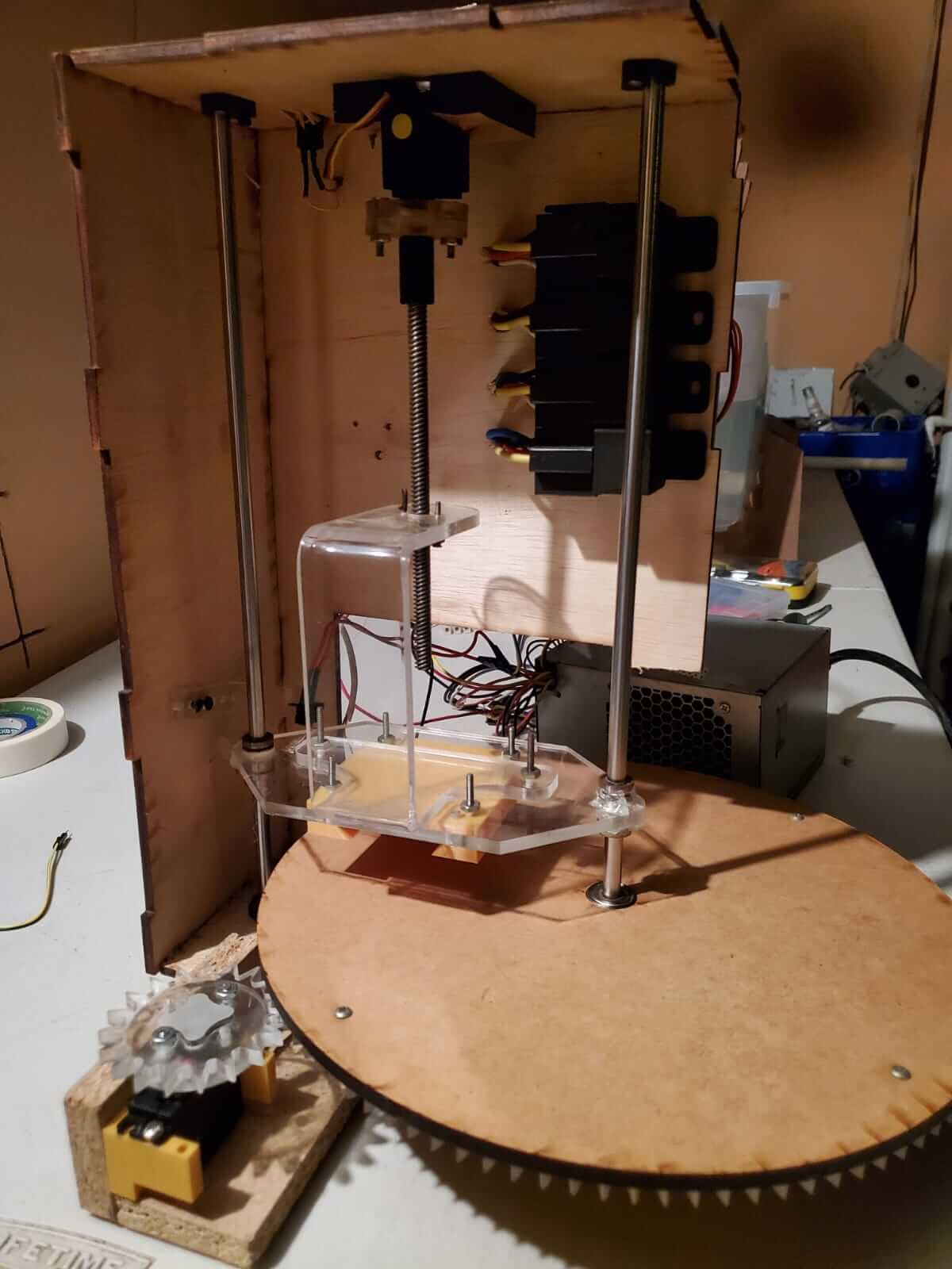
For my contribution to the machine design, I took on the task of designing and building the actuator press and the electronic system.
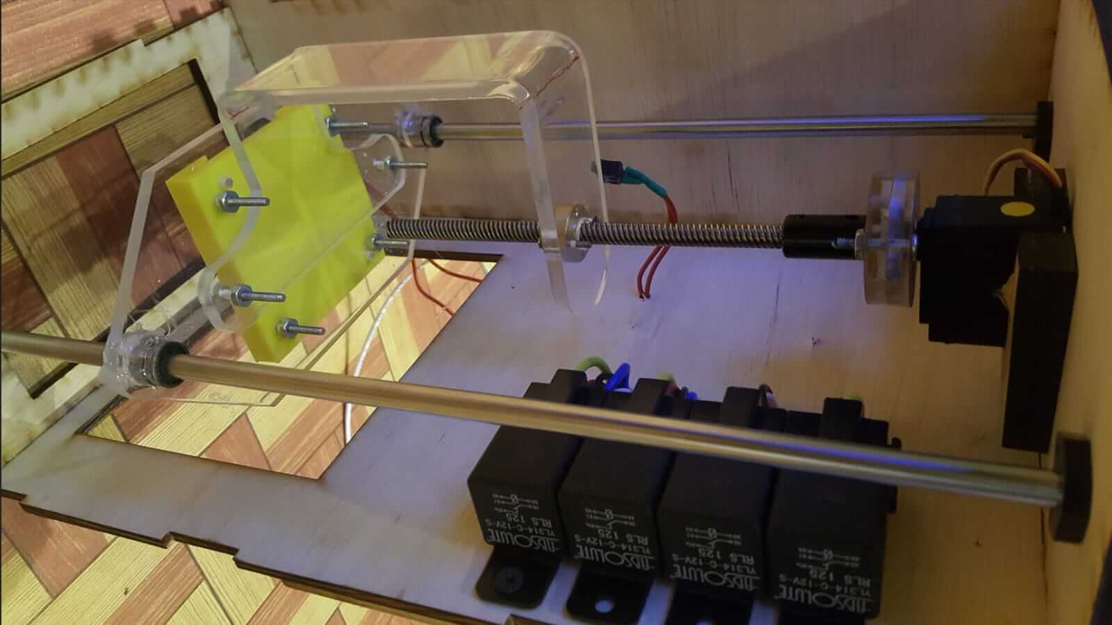
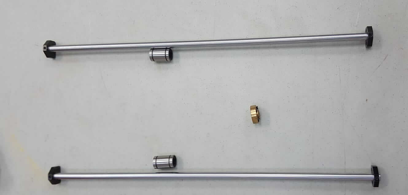
I decided to have the press plate slide along linear shafts using linear bearings. I found these parts from an old 3D printer and I found a nut that can go on a threaded bar as well as support for the shafts.
I designed the main press plate for actuator press using CorelDraw.
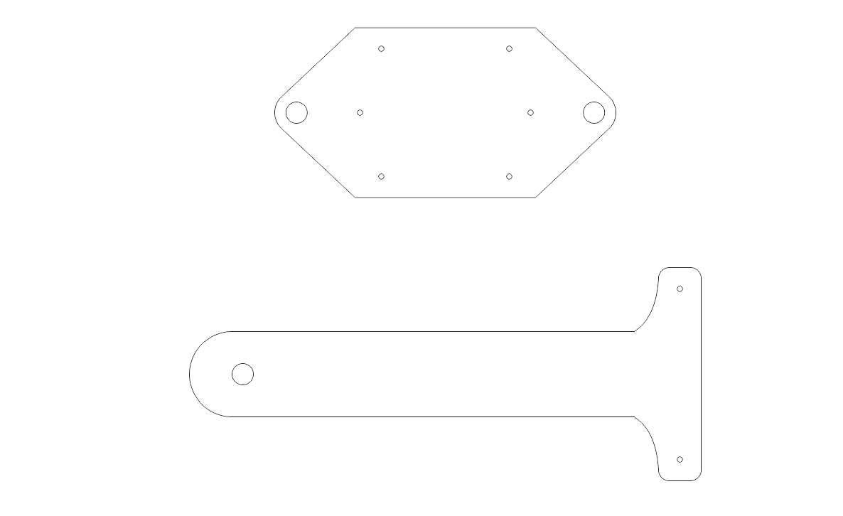
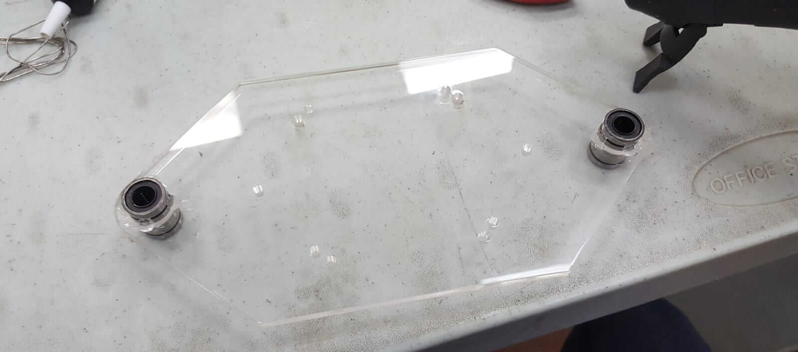
I cut the plate with the laser cutter using 1/4" acrylic and I attached the linear bearings to it. The holes were cut slightly bigger than the linear bearings so I used some hot glue to ensure they don't fall out. My colleague who did 3D printing part of the machine printed a block to hold the cookie cutter, so I attached it at the same time.
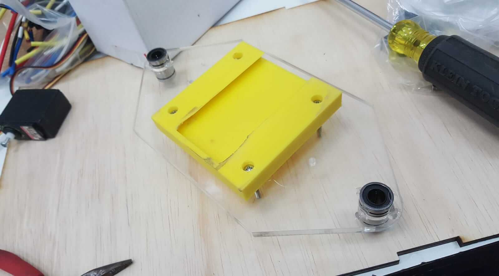
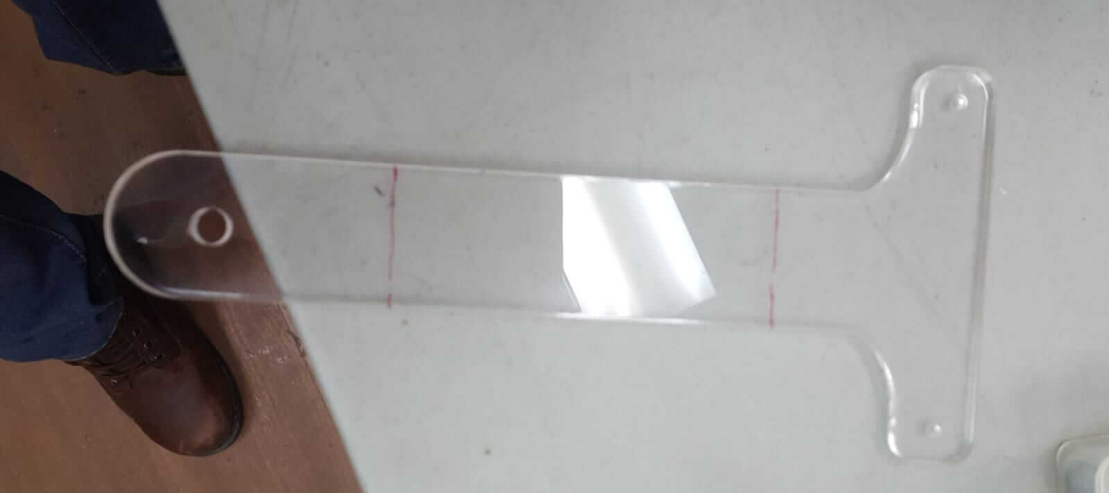
I designed and cut out a bracket to hold the press plate and connect to the actuator. The bracket was cut out of acrylic and I bent it into the shape I wanted by heating the spot that I needed to bend.
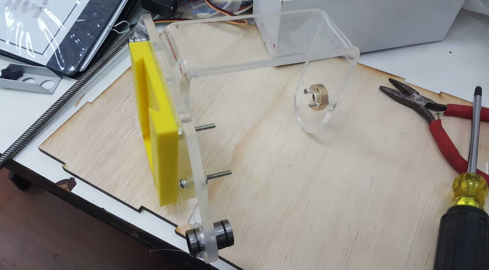
I attached one end of each of the linear shafts to the chassis.
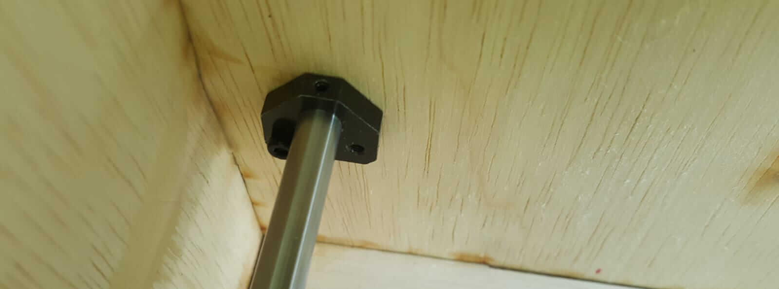
I then fitted the press plate unto the linear shafts and aligned them. The linear shafts not only allows the press plate to slide easily but also supports its.
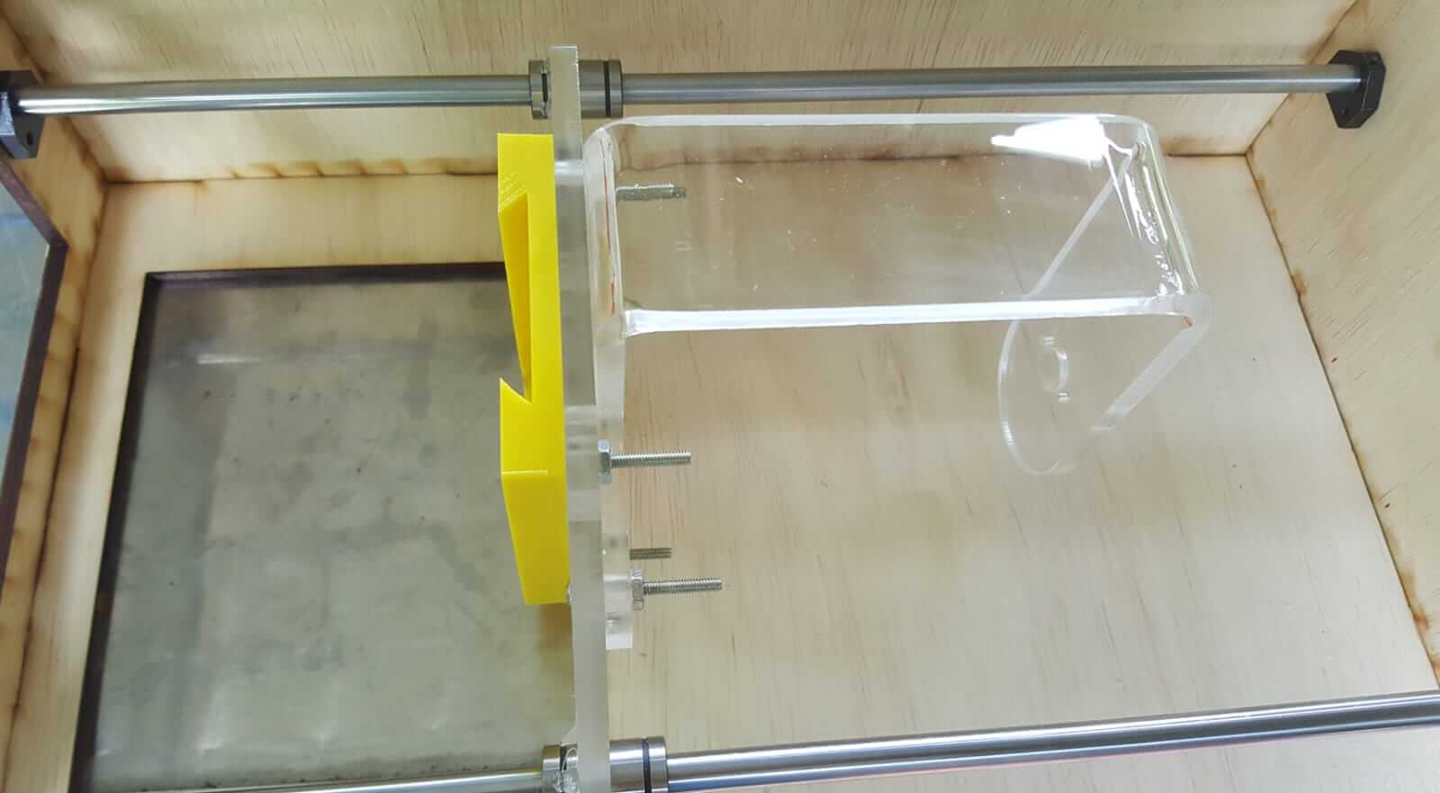
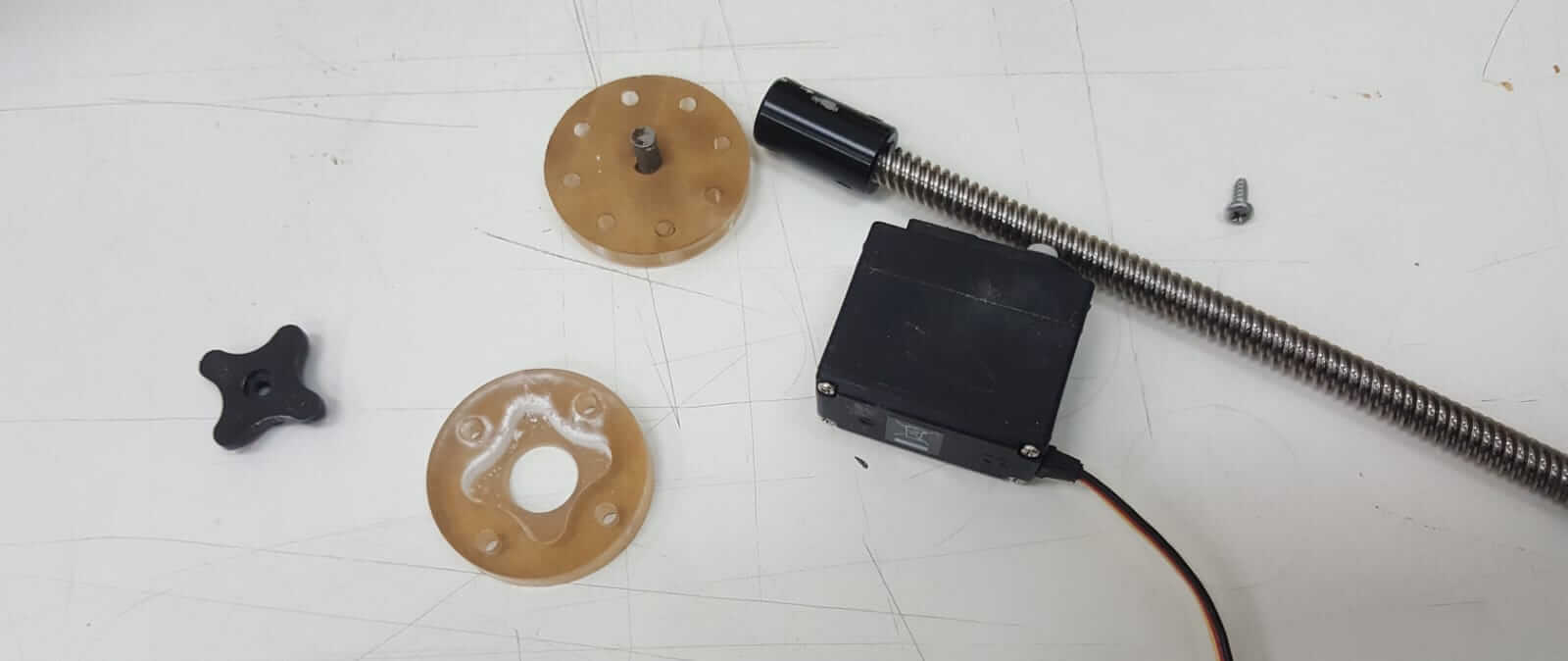
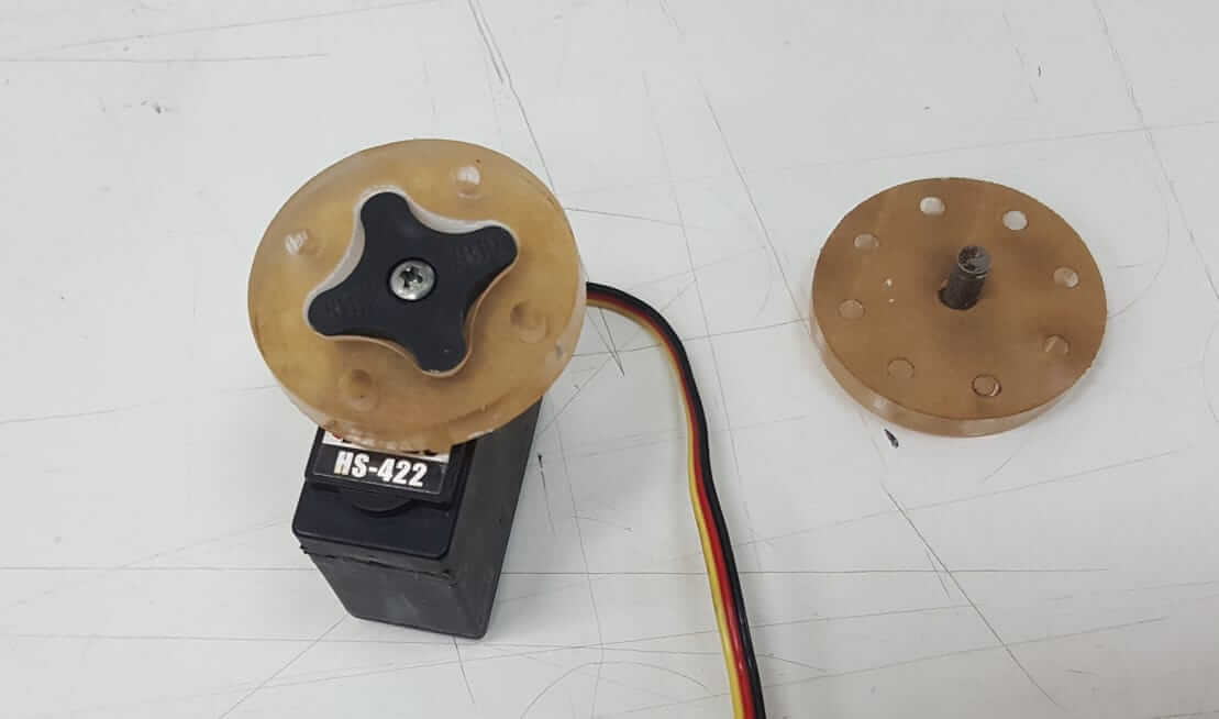
I also took a threaded shaft from the old 3D printer. This was the key part of the actuator. So I attached the bar to the press plate bracket and attached a union to connect the bar to the motor.
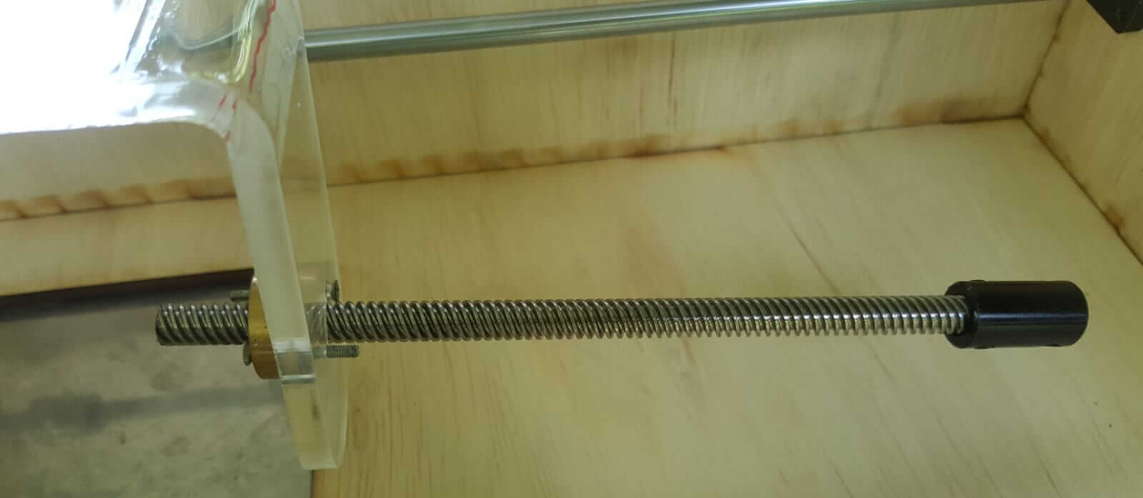
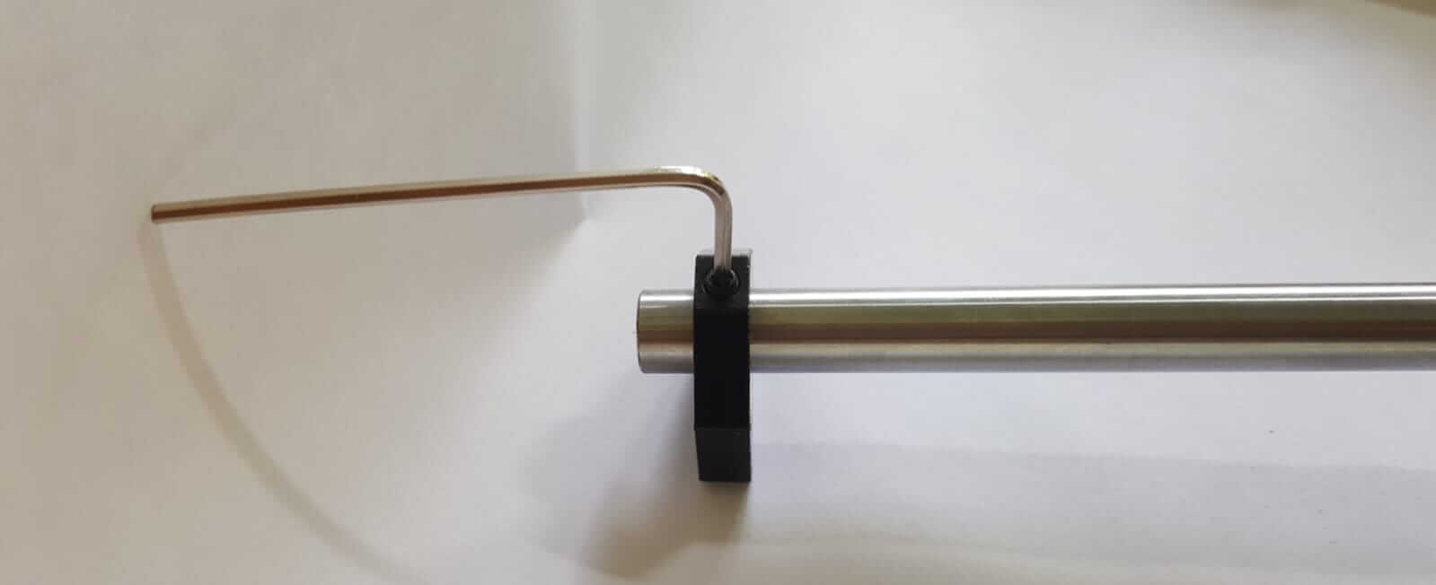
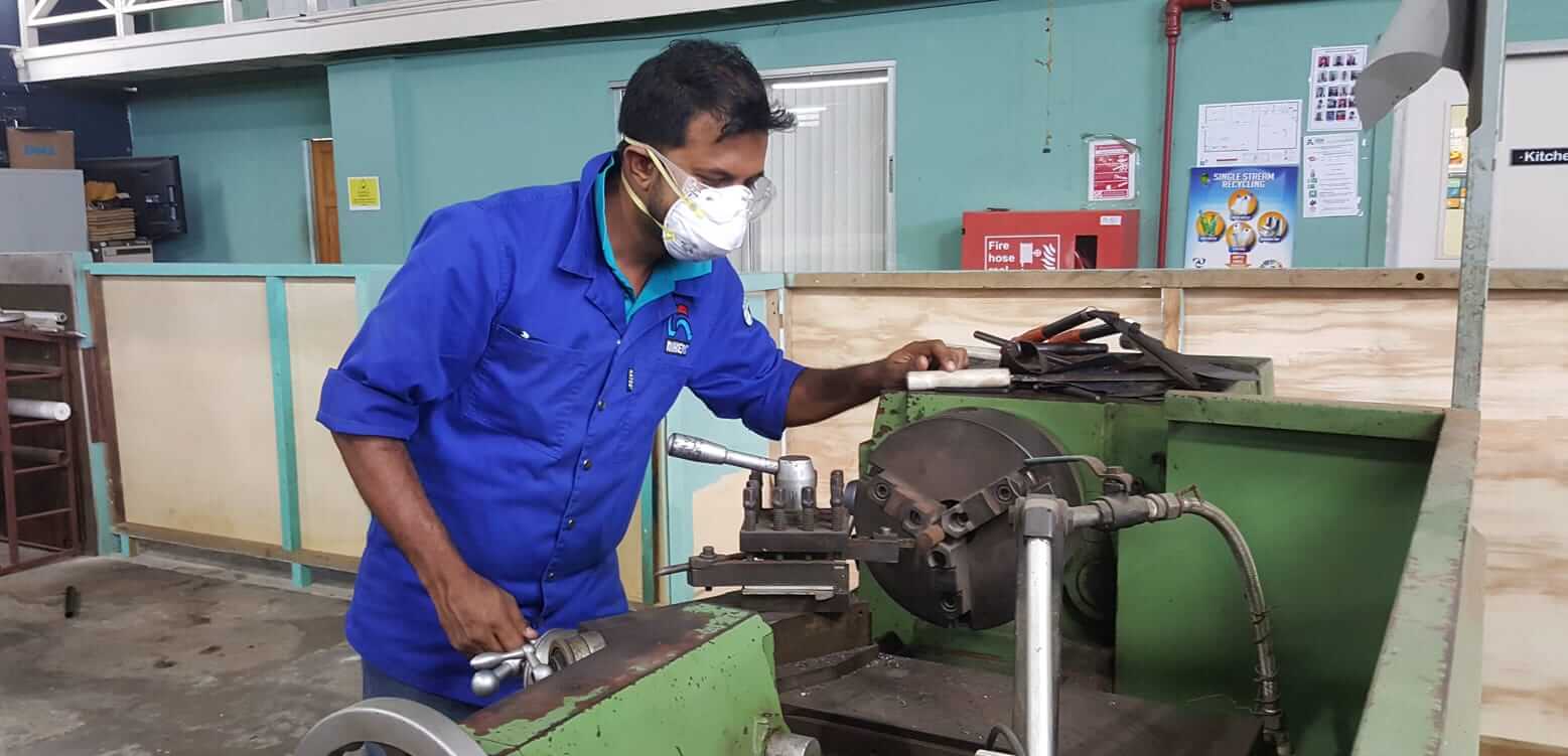
The connector I used for the threaded shaft was too thick to connect to the motor's head so I had to make an attachment for this. I cut a piece of acrylic using the CNC router to create two flanges with holes at the center but pocketed on the inside. The pocket on one flange will hold the mounting head of the motor while the other will hold a piece steel to connect to the threaded shaft that I milled using a lathe.
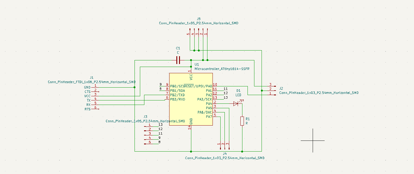
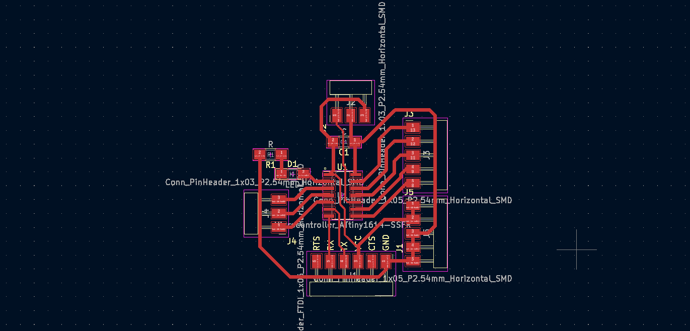
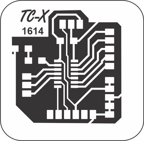
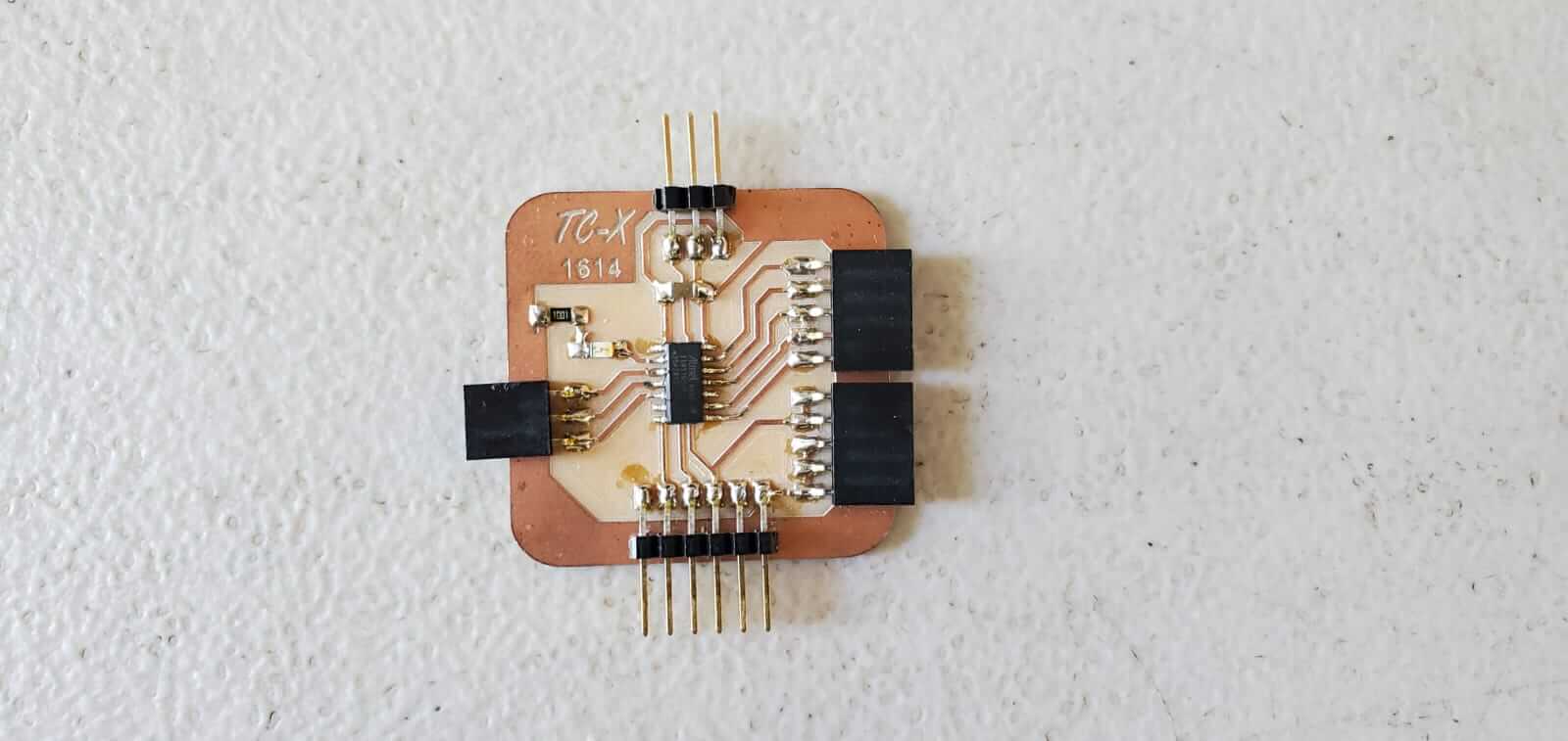
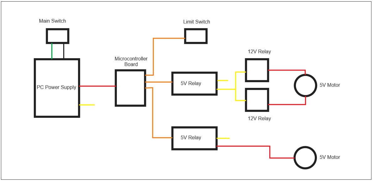
For this part of the project I built an MCU using the ATTiny 1614. The initial stage for powering this machine we didn't recieve our shipment of electronic components to use a microcontroller. Due to this I disconnected the servo control within the motor making them work like a normal DC motor. To power these motors I used relays and limit switches to automate the interchanging of the motor's direction. We eventually recieved our electronic components so I designed the 1614 MCU.
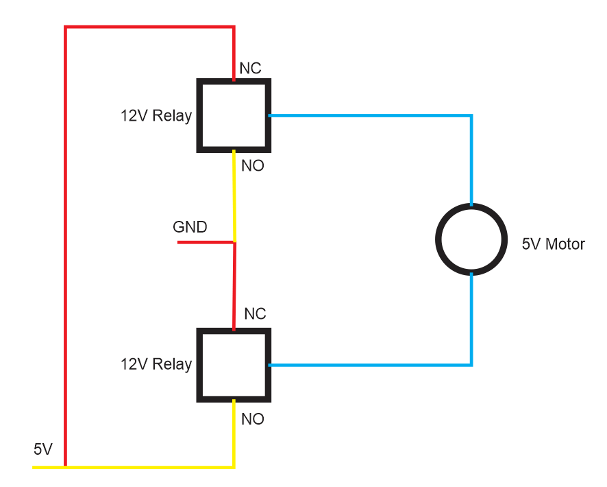
I tried controlling the motors with the microcontroller board, but it could not supply sufficient power to them. So I had to reuse two of the 12V relays and one of the limit switches. I also included two 5V relays. I used a computer power supply to power the machine. This was convenient because this provided both a 12V (yellow wire) out and a 5V (red wire) out.
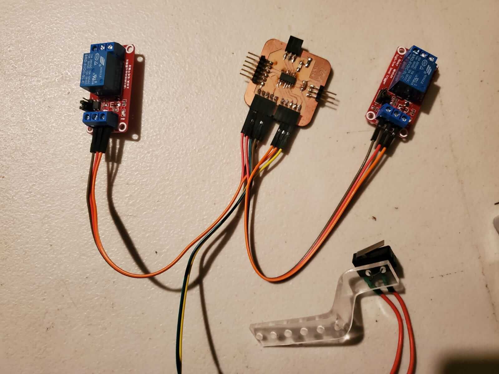
One of the 5V relay was used to power the 12V relays, which were used to switch polarity going to the actuator motor.
I included the limit switch to assist with the programming. Initially the program ran without a limit switch but if the machine was turned off while the actuator was higher or lower than its required start position, the next time it was powered, the press would either be too high or to low which would cause it too crash. So the limit switch was added. Everytime the machine is powered, no matter the last postion of the press, it would always go up until it touches the limit switch which is its required start position.
When the actuator 5V relay is LOW the motor lifts the press and when its HIGH the press goes down.
                int led = 0;
                int conveyer = 8;
                int actuator = 9;
                int lim = 10;

                void setup() {
                  pinMode(0, OUTPUT);
                  pinMode(8, OUTPUT);
                  pinMode(10, INPUT_PULLUP);
                  pinMode(9, OUTPUT);

                }

                void loop() {

                digitalWrite(actuator, LOW);

                    if(digitalRead(lim) == 0)
                    {
                      delay(1000);
                      digitalWrite(actuator, HIGH);
                      delay(6000);
                      digitalWrite(actuator, LOW);
                      delay(5000);
                      digitalWrite(conveyer, HIGH);
                      delay(1000);
                      digitalWrite(conveyer, LOW);

                    }
                }

A block diagram of the electronics.
The automated cookie cutter machine
The cookie cutting molds needed to be deeper for a better cut and also our "cookie dough making skills" aren't so good.