Introduction.
This week was very interesting, I was able to get to know the different output components that exist to control events in electronics, among them are the displays, motors, speakers, relays (it is capable of controlling a higher power output circuit than the input one, can be considered, in a broad sense, as an electrical amplifier. As such they were used in telegraphy, acting as repeaters that generated a new signal with current from local batteries from the weak signal received by the line)
individual assignment:
Add an output device to a microcontroller board you've designed, and program it to do something.
For this week's assignment I wanted to do a humidity&temperature indicator, since here usually the weather is hot and humid I thought it would be interesting to check that data from time to time inside a room.
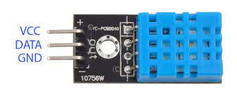
dht11 temperature and humidity sensor pinout.
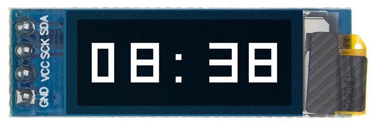
SSD1306 OLED 128x32.
Prototype
First, I did a little prototype using an Arduino UNO board with a DHT11 module and an SSD1306 128x32 OLED with the following connections
SSD1306 128x32 OLED
| SSD1306 128x32 OLED PIN | ARDUINO PIN |
| SDA | A4 |
| SCL | A5 |
| VCC | 3V3 |
| GND | GND |
DHT11 module
| DHT11 module PIN | ARDUINO PIN |
| S | Digital 2 |
| - | GND |
| + | 5v |
Then I wrote a sketch in the Arduino IDE that uses the following libraries: DHT sensor library by Adafruit Adafruit SSD1306 by Adafruit
        ```cpp

#include
#include
#include
#include
#include
#include
#include


Adafruit_SSD1306 display(128, 32, &Wire, -1);
DHT_Unified dht(2, DHT11);


void setup() {
  dht.begin(); //initialize the dht11 sensor

  Serial.begin(9600); //just for debugging
  if(!display.begin(SSD1306_SWITCHCAPVCC, 0x3C)) { //initialize the oled display
    Serial.println("SSD1306 allocation failed");
    for(;;); //if it fails just loop forever
  }
  delay(500);
  display.clearDisplay(); //set the display empty
  display.setTextSize(2);
  display.setTextColor(WHITE); //the oled i'm using has white text
  display.display(); //update the display
}

void loop() {
  display.clearDisplay(); //set the display empty

  //Create a sensors_event_t struct, where the reads will be saved
  sensors_event_t event;

  //read the temperature
  dht.temperature().getEvent(&event);
  //if there is no temperature to read, just add "NaN" to the display
  if (isnan(event.temperature)) {
    display.print("NaN");
  }
  else {
    //if there is actually a value to work with, print the temperature with this format: 30.5*C
    display.setCursor(0, 0);
    display.print(event.temperature);
    display.setTextSize(1); //make the * smaller
    display.print("*");
    display.setTextSize(2);
    display.print("C\n"); //go to the next line
  }

  //read the humidity
  dht.humidity().getEvent(&event);
  //if there is no humidty to read, just add "NaN" to the display
  if (isnan(event.relative_humidity)) {
    display.print("NaN");
  }
  else {
    //if there is actually a value to work with, print the humidity with this format: 60.00%
    display.print(event.relative_humidity);
    display.print("%");
  }

  display.display(); //update the display

  delay(250);//fill with new data every 250 ms
}
Uploading the code:

And it looks like this:

After everything got working properly, I started to design the board.
Board design
For this board, I decided to go with the same microcontroller as the Arduino UNO since the actual code size got as big as 17.924 kB and according to the datasheet of the original MCU I was planning to use, an Attiny45, only has 4KB of flash available.
Then I had to choose what kind of package type I was going to use for this board, by taking a look at the datasheet (https://ww1.microchip.com/downloads/en/DeviceDoc/ATmega48A-PA-88A-PA-168A-PA-328-P-DS-DS40002061B.pdf p.12) we find available package formats for this microcontroller

For starters, 28-VQFN and 32-VQFN get discarded, since they look a bit hard to solder or even get milled.

So, with 32-TQFP and 28-SPDIP left the only thing left to do is check if they are millable or not, so I just created a new KiCad project where I put both MCUs package formats


Then I generate a netlist


And open it on the PCB editor

Then just plot the board as SVG only including the F.cu layer

After loading the SVG to Fabmodules, using a tool with 0.3mm of diameter, the pads of the 32-TQFP package can't be milled at all, so DIP-28 is the one to go

The board schematic is done using the following components:

Table
| Reference | Library reference | Footprint |
| U1 | MCU_Microchip_ATmega:ATmega328-PU | Package_DIP:DIP-28_W7.62mm |
| SW1 | fab:BUTTON_B3SN | fab:Button_Switch_THT:SW_PUSH_6mm |
| J2 | Connector:Conn_01x02_Female | Connector_PinHeader_2.54mm:PinHeader_1x02_P2.54mm_Vertical |
| J3 | Connector:Conn_01x03_Female | Connector_PinHeader_2.54mm:PinHeader_1x03_P2.54mm_Vertical |
| J4 | Connector:Conn_01x04_Female | Connector_PinHeader_2.54mm:PinHeader_1x04_P2.54mm_Vertical |
The next thing to do is to route the board, after moving and connecting the pads, it ends up looking like this:

For this board, I used 0.35mm traces for the data lines and 0.6mm for the power lines, with a 0.5mm clearance.
After the board is done, the next step is to export everything to mill it, since this time I will be using a different machine, the procedure will not be the same as in past weeks.
First, plot the layers F.cu and Edge.Cuts with plot format set as Gerber

Then, click on "Generate Drill Files" and set everything like is at the image, finally, click on "Generate Drill File" at the bottom of the newly opened window

For the routing, I used Flatcam 8.994 beta (get it from here https://bitbucket.org/jpcgt/flatcam/downloads/).
First, open FlatCAM and drag the files that got generated when plotting (extension .gbr and .drl)

Then zoom out (with the scroll wheel on the mouse or with 2 fingers from center to outside on a trackpad), select the board area by clicking from a corner and dragging to the other

After that, press M on the keyboard (move command) and click somewhere inside the board, then just drag the board near the cartesian origin and click again to place the selection


At the left we have a menu with 3 tabs (Project, Properties & Tool) Project being the default tab where we can select the Gerber files or the Excellon one, also geometry objects or cncjobs that get generated, for basic navigation using the right-click and dragging will pan allow you to pan across the grid.
To generate the first CNCjob, select the Gerber file that contains "Edge_Cuts" on its name

Then go to Properties and select Cutout Tool

This will send us to a different tab, where we can fill with parameters depending on what we need to cut the edges of the board
Tool Dia: this is the diameter of the tool used
Cut Z: how deep is going to cut
Multi-Depth: how deep each pass is going to be (when active this will continue to cut in N steps of Y depth until Cut Z depth is reached)
Margin: how far apart from the original object is going to cut
Gap size: the thickness of the gaps left after cutting
Gap type(thin) - Depth: how much is going to cut from the top of the gaps left
Gaps: how many gaps is going to leave
Here I filled those with these parameters:
Tool Dia: 1.4
Cut Z: -1.8
Multi-Depth: 0.6
Margin: 0.1
Gap size: 0.5
Gap type(thin) - Depth: -1.0
Gaps: LR
After everything is set, just click "Generate Geometry" (the first one just below Gaps, the other one is just for rectangular geometry and this one is not)

Then go back to Properties, you will have selected the geometry freshly generated a few moments ago, here at the subtitle "Parameters for: Tool N" we have
Travel Z: how high the drill will be when doing travel moves
Feedrate X-Y: how fast the drill will move when doing cuts (in mm/m)
Feedrate Z: how fast the drill will plunge (in mm/m)
Spindle speed: how fast the spindle will rotate (in RPM)
Dwell: wait N seconds before start cutting (so the spindle can reach full velocity)
Here I filled those with these:
Travel Z: 2
Feedrate X-Y: 120
Feedrate Z: 60
Spindle speed: 5000
Dwell: 1
Finally, just click on "Apply parameters to all tools" and "Generate CNCJob object"

Go back to Project and select the one with "F_Cu" in its name, then go to properties and select the NCC tool

Here, right-click on the second tool from the tools table and delete it.

Set the first tool diameter to 0.4 and the Tool type (TT) to "V".

Leave everything as is and click on generate geometry, then go back to properties.
Once back at properties, the first thing to do is adjust the V-tip Dia and V-tip Angle to a value that changes Cut-Z to -0.12
Here I used 0.1 and 102.
.

For the parameters below
Travel Z: how high the drill will be when doing travel moves
Feedrate X-Y: how fast the drill will move when doing cuts (in mm/m)
Feedrate Z: how fast the drill will plunge (in mm/m)
Spindle speed: how fast the spindle will rotate (in RPM)
Dwell: wait N seconds before start cutting (so the spindle can reach full velocity)
I used these:
Travel Z: 2
Feedrate X-Y: 50
Feedrate Z: 60
Spindle speed: 5000
Dwell: 1
Then just like with the Edge-Cuts, click on "Apply parameters to all tools" and "Generate CNCJob object"
Go back to "Project" and select the one that ends with ".drl", then go to "Properties"
Here, click on the Drilling tool
.

Again, a bit of the same parameters as before, here I filled with:
Cut Z:-2.5
Travel Z: 2
Feedrate Z: 150
Spindle speed: 5000
Dwell: 1
And enabled tool change with:
Tool change Z:22
Preprocessor: GRBL_11_no_M6
Then just like with the Edge-Cuts and F.Cu, click on "Apply parameters to all tools" and "Generate CNCJob object"
.

Go back to Project, here you will find at the group "CNC Job" three objects, just right-click one by one and click on save, then just choose where you want to save them.
.

This machine uses CNC.js as its interface, just by drag and dropping the gcode (.nc or .gcode) and setting the X-Y-Z origin is ready to go.
.

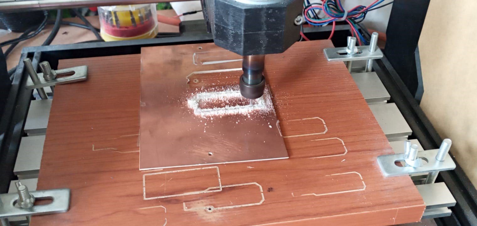
Starting the cut.
Board finished.

Components
| Q. | Name | |
|---|---|---|
| 1 | Female header 01x04 | |
| 1 | Male header 01x02 | |
| 1 | Male header 01x03 | |
| 1 | ATMEGA328-PU | |
| 1 | dht11 temperature and humidity sensor | |
| 1 | SSD1306 OLED 128x32 | |
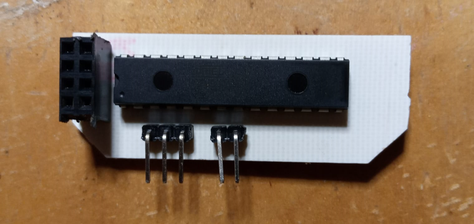
Electronic components integrated on the board.
Top side.
The pins that do not join is because they are not used for this practice.
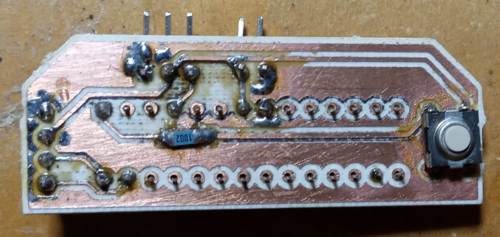
Bottom side, this distribution was made to reduce the size of the carcass.
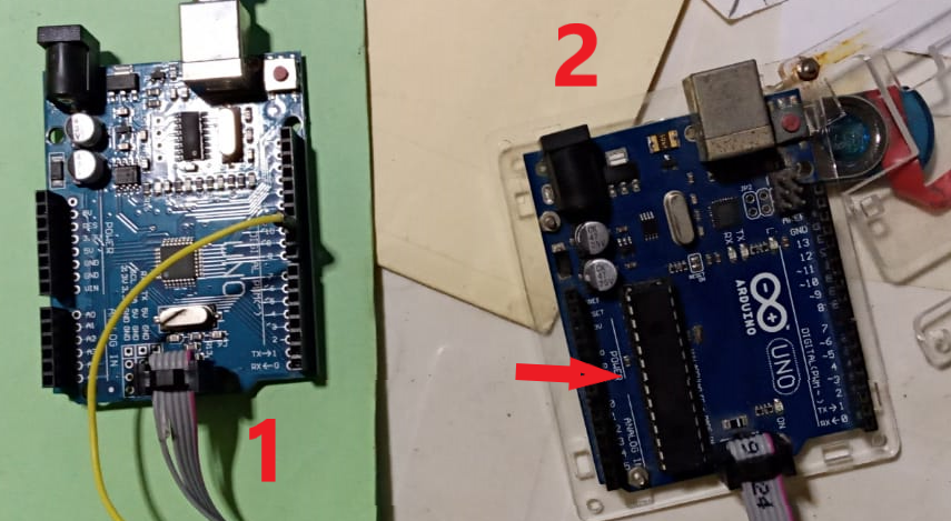
To program the atmeaga328 you used two arduinos, the first is the programmer and the second is to program it.
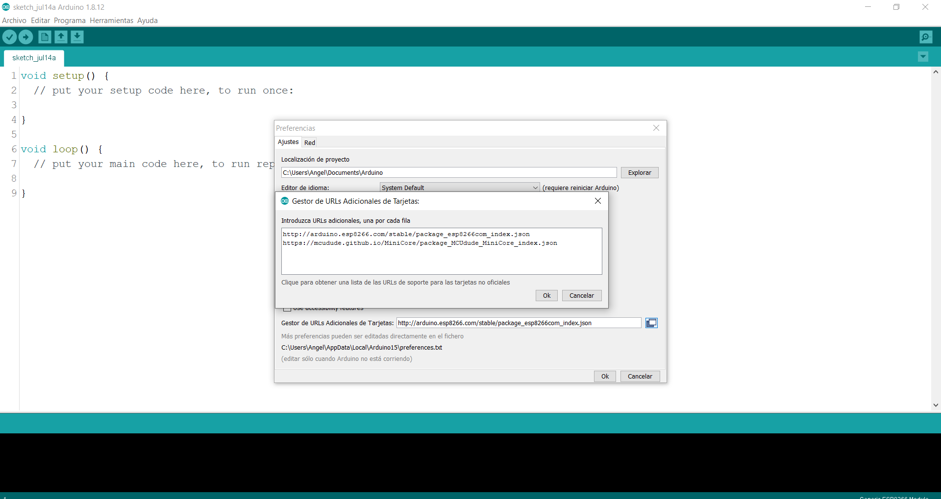
In the Arduino IDE, click the File menu, select preferences, and add the URL https://mcudude.github.io/MiniCore/package_MCUdude_MiniCore_index.json.
.
In the menu Tools select board> Board manager and install minicore.
.
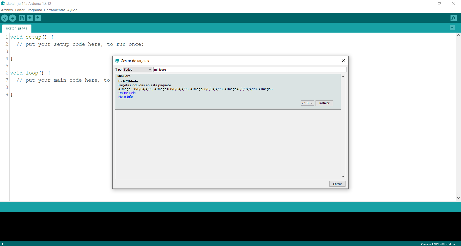
I now selected the ATmega328 board.
.

Upload using programmer.
.

Programming the ATmega328 microcontroller, after a few seconds of waiting, I am excited because everything went well with the programming.
.
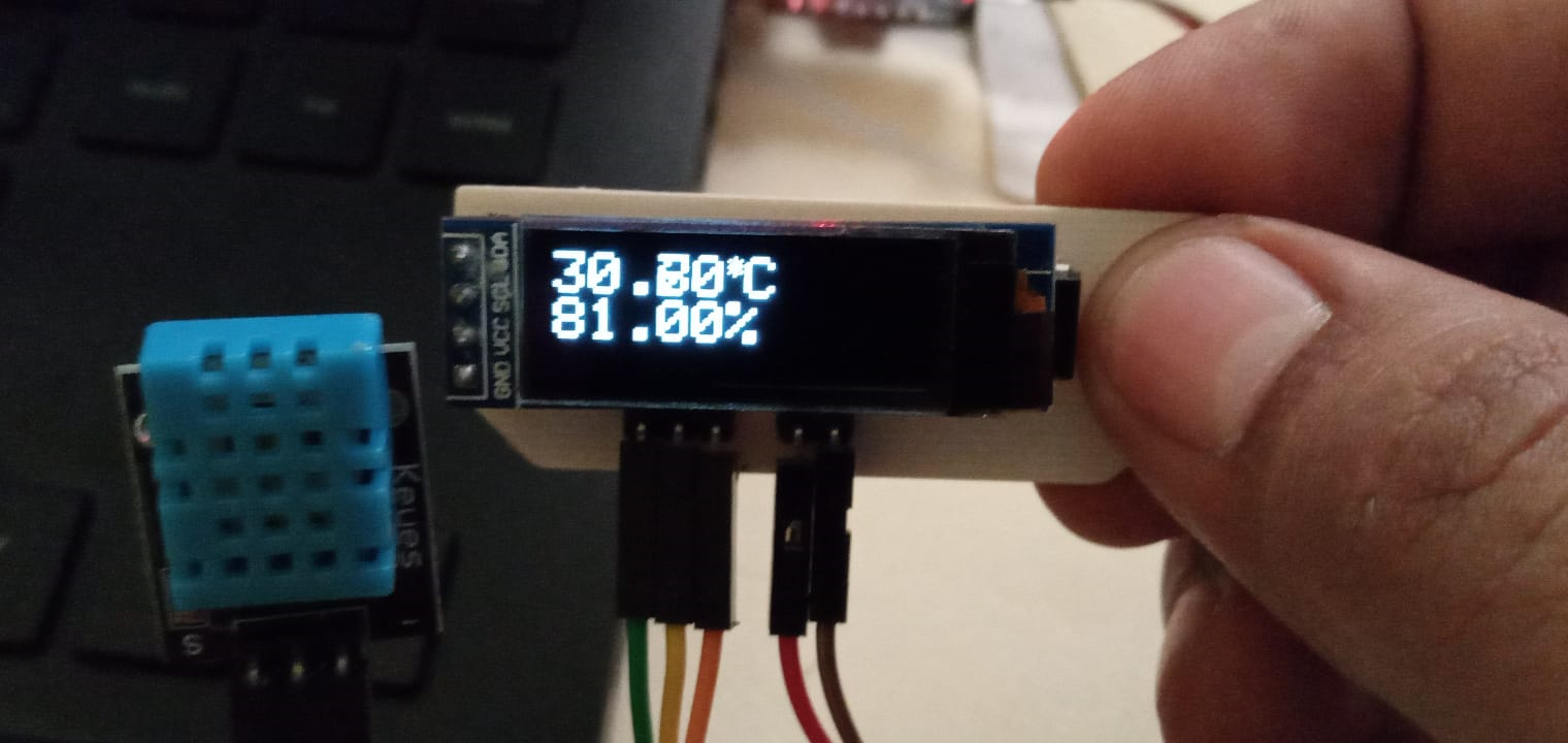
Finally the input and output device is connected and displays both the temperature and the humidity.
.
Group assignment.
measure the power consumption of an output device.
-
Taking into account the connection pins of a sg90 servo motor, the ground terminals must be connected to the ground of the Arduino programming board, then the voltage input or power supply of the actuator must be connected to the 5v output of the Arduino; Finally, connect pin 9 of the Arduino to the control terminal of the actuator.
Servo pin Arduino pin GND GND V 5 V Signal pin 9 -
Perform the following servo control programming:
// We include the library to be able to control the servo #include// We declare the variable to control the servo Servo servo motor; void setup () { // We start the serial monitor to show the result Serial.begin (9600); // We start the servo so that it starts working with pin 9 servoMotor.attach (9); } void loop () { // We move to the 0º position servoMotor.write (0); // We wait 1 second delay (1000); // We move to the 90º position servoMotor.write (90); // We wait 1 second delay (1000); // We move to the 180º position servoMotor.write (180); // We wait 1 second delay (1000); } -
Now, to carry out the measurement we will use a multimeter, which we will connect and put in direct current analysis. We continue to measure the energy consumption of the servo, which based on its power supply at its voltage terminal, we can guess that it will be 5 volts.
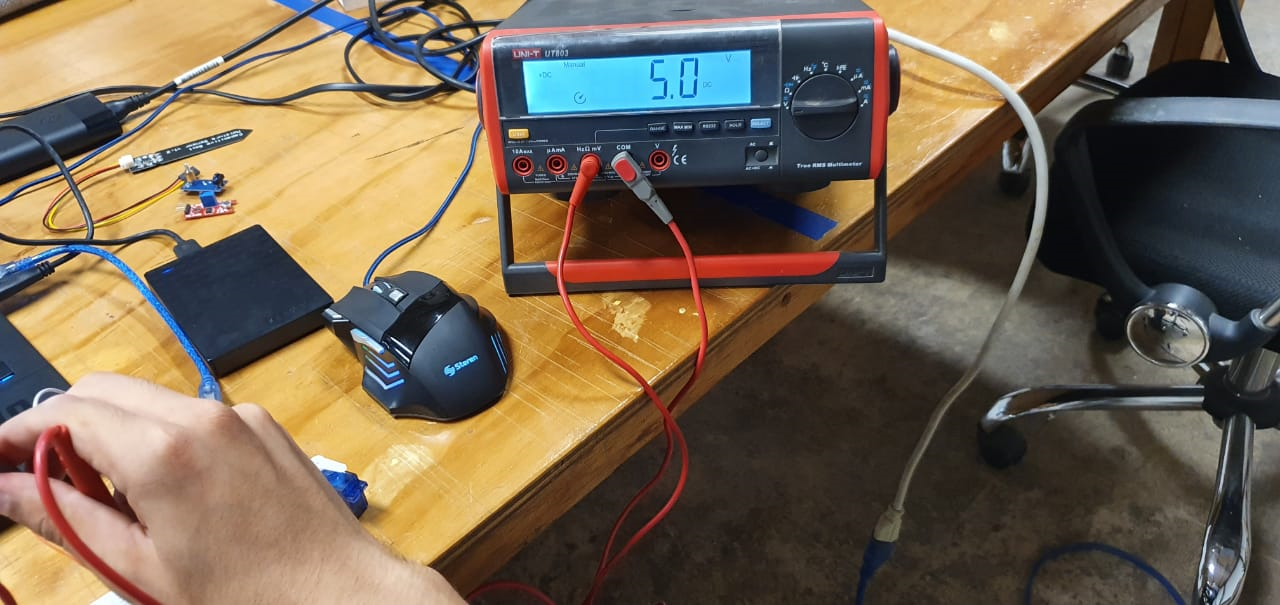 Taking into account the current and voltage consumption of the actuator, we can analyze its power using the formula
CURRENT x VOLTAGE = POWER: 0.22 x 10 ^ -3 x 5 Volts = 0.0011 Watts
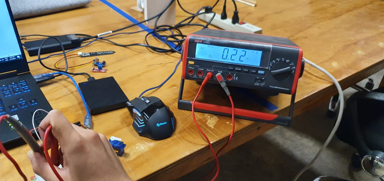
Now using a basic multimeter, I am going to measure the power consumption of my board.
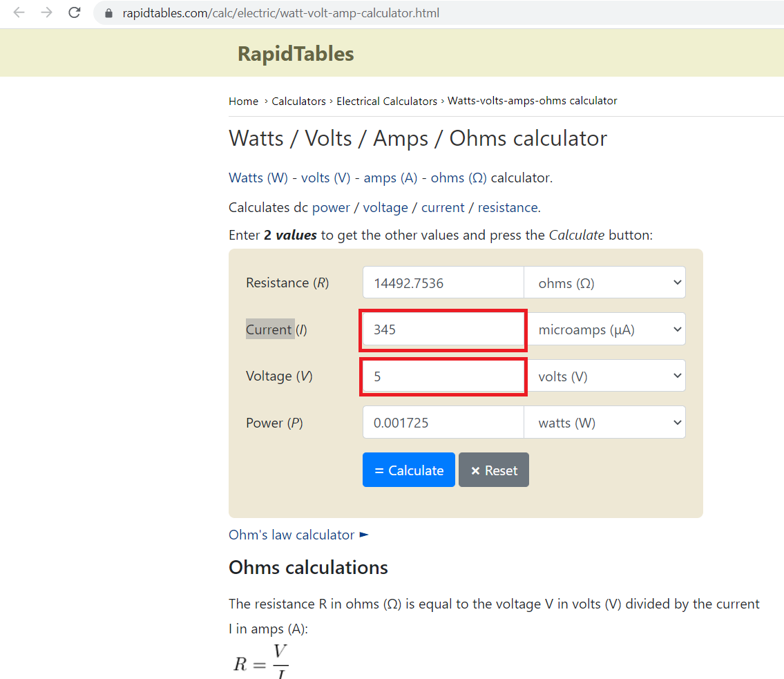
The value shown in the multimeter changes, the first value was 345, I will use that to do the calculation.
0.345 x 10 ^ -3 x 5 Volts = 0.001725
On the internet there is a site that explains how to calculate, the following image shows the results using that site, I only enter the voltage and current.
