Introduction.
This week was very interesting because it allowed me to explore and know the various types
of materials that can be used to design electronic boards, it is an incredible experience.
Electronic cards of various sizes can be designed and manufactured and can be flexible (for
example to fit in a shirt) or rigid which are regularly mounted on a housing.
To achieve this, we start from the design of a 2d circuit, then it is necessary to use a
machine in my case I used the monofab srm-20.
Group assignment: characterize the design rules for your PCB production process.
monoFab SRM-20
Desktop Milling Machine
This machine is capable of cutting a wide variety of materials including
chemical wood, acrylic, and ABS. It is also capable of a range of accuracy
settings from prototype to product design. Plus its small size and fully
covered design allows you to enjoy cutting more safely and with peace of
mind.
Exclusive CAM software is included so you can start cutting immediately after creating
cutting data.
Roland monoFab SRM-20
Part Names and Functions
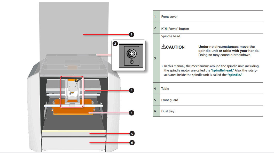
The connection to the computer is via USB.
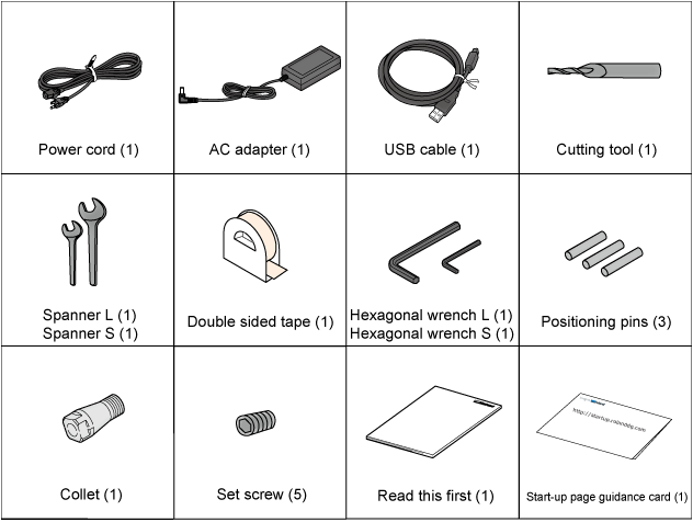
The following items are packed together with the unit. Make sure they are all present and
accounted for.
Manual
Unsuitable installation sites. Following locations can cause malfunction or poor cutting quality. Locations subject to large fluctuations in temperature or humidity. Locations subject to shaking or vibration. Locations where the floor is tilted, not level, or unstable. Dusty locations. Locations exposed to direct sunlight. Locations near air-conditioning or heating equipment. Locations where it is difficult for heat generated when using the machine to escape. Locations exposed to water or moving air. Locations exposed to considerable electrical or magnetic noise, or other forms of electromagnetic energy.
The space shown in the figure is required in order to use this machine.
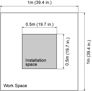
The height of installation should be 0.6 m (23.7 in.) or higher above the work floor. This machine is desktop type. Install in a location that allows easy access to areas such as the power switch during operation.
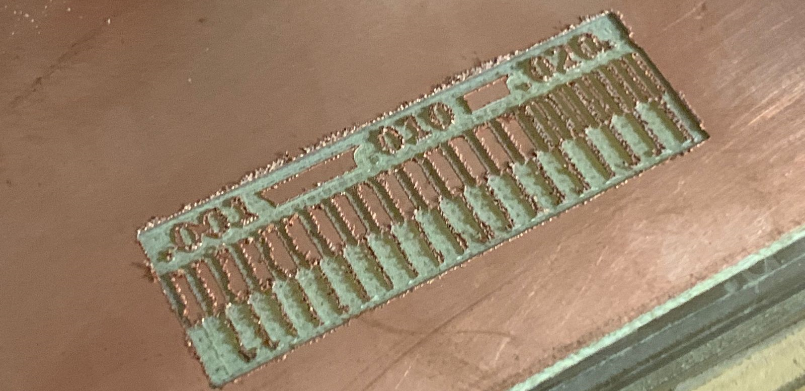
To learn more about using the Roland monoFab SRM-20, I'm going to run the line test that Neil showed us in class, to check the machine's performance with a 1/64 "cutter.
I set the values, at the point x = 0, y = 0 and with a speed of 1 mm / s for the 1/64 cutter. After finishing milling the inner lines, I clean the board and change the mill for the 1/32 with the same values x = 0, y = 0 and speed 1 mm / s. Being a different mill, you have to position Z again.
Final result of the test, the lines are not well defined, this is because the bur is not new and I do not have another one to perform the test again.
individual assignment:
Make an in-circuit programmer by milling and stuffing the PCB,
test it, then optionally try other PCB processes.
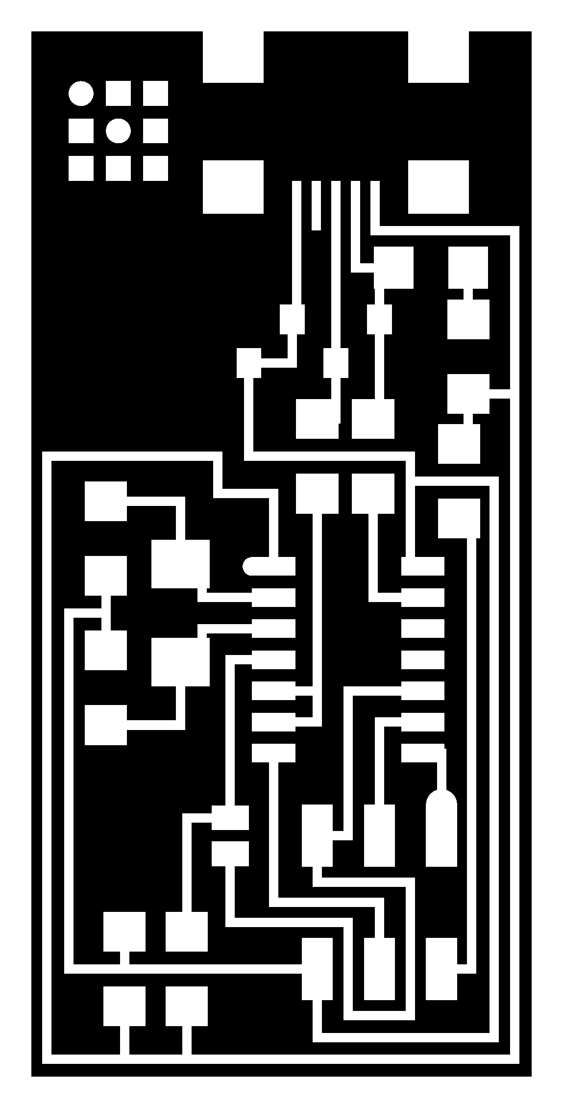
To carry out this task I chose the design hello.ISP.44 board components traces
interior, I downloaded the image
Then use the mods of http://fabmodules.org/ create the files required to make the cut in the
milling machine.
The following image shows the data for general interior model.
- After opening the url in the browser, click on input format and select image png
- Select the hello.ISP.44.interior.png image that was previously downloaded
- Select the output format, for the type of milling machine in this case it is Roland mill.
-
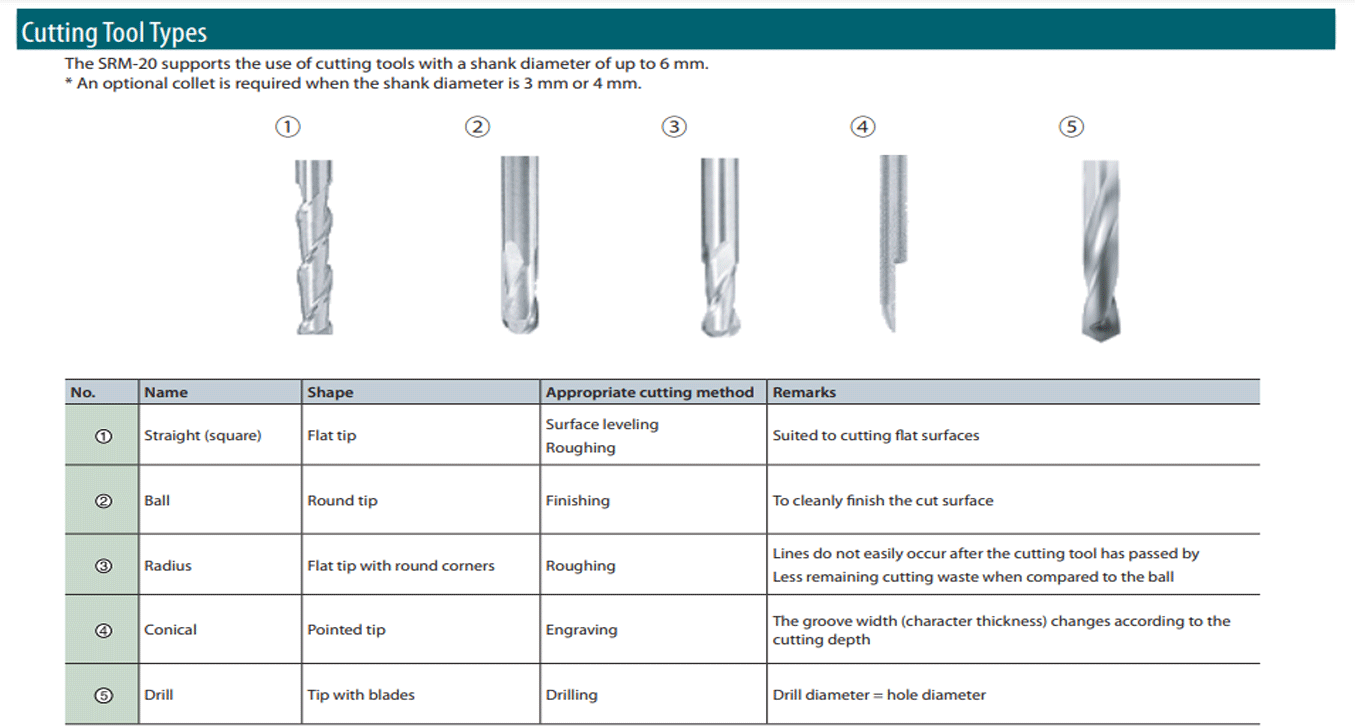
Click on process and select pcb outline (1/32)
This means that a 1/32 cutting tool is required for cutting. -
In this step you have to change several parameters, starting by selecting on the
machine: SRM-20
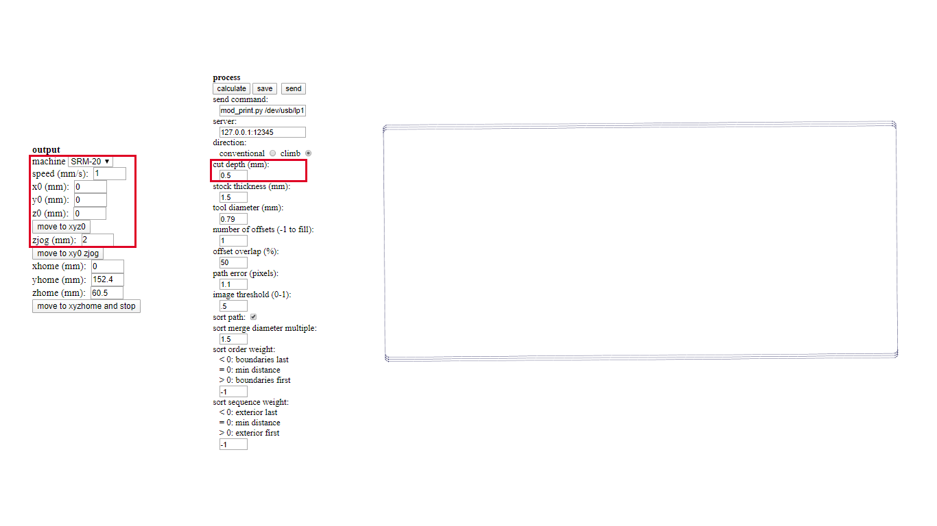
You also have to change the speed to 1 and the x, y and z values are set to 0, clicking on calculate generates the image which with the right mouse button we can move.
Finally click save and the file to cut is ready. - For this I use the image hello.ISP.44.traces.png
- Select the output format, for the type of milling machine in this case it is Roland mill.
-
Click on process and select pcb traces (1/64)
This means that a 1/64 cutting tool is required for cutting. -
In this step you have to change several parameters, starting by selecting on the
machine: SRM-20
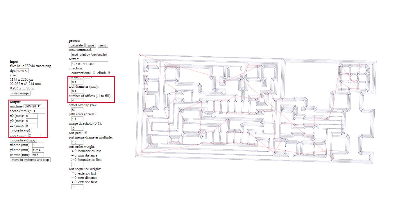
You also have to change the x, y and z values are set to 0, clicking on calculate generates the image which with the right mouse button we can move.
Finally click save and the file to cut is ready.
Files
-
Insert a cutting tool into a collar.
Do not insert into the part of an edge.
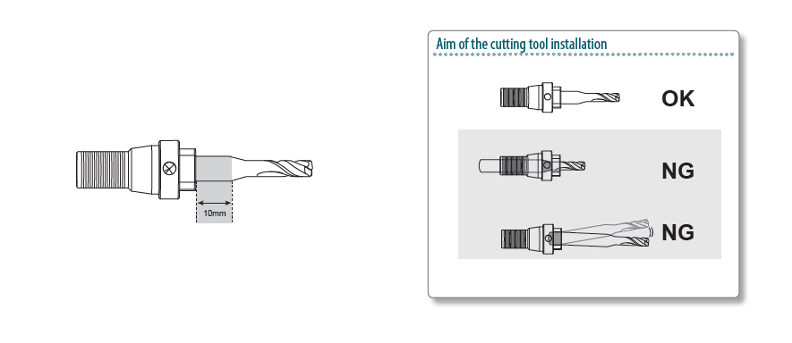
-
Tighten the set screw with hexagonal wrench.
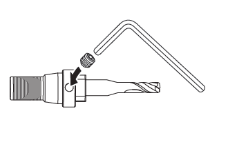
-
Click [View] of VPanel.
A spindle head moves to a center and a table moves to the front..
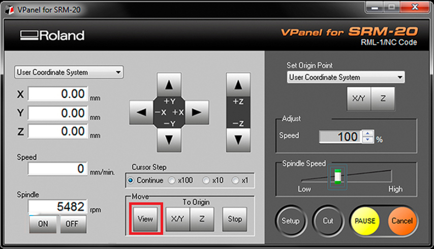
-
Loosely tighten the collet with cutting tool.
Insert the collet, and then loosely tighten.
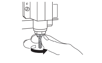
-
Fully tighten the collet.
Tightly secure the collet by using two spanners.
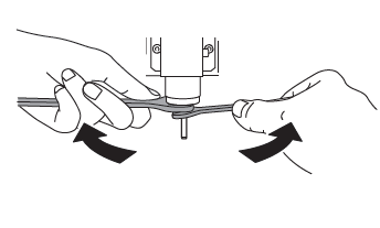
-
Attach the material to the table.
Stick double tape over the material.
One side of adhesion is made large so that the material does not separate during
cutting.
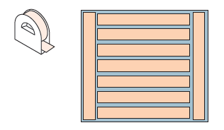
-
The next step was to open theopen VPanel for SRM-20.
A nice tip is to warm the spindle for 10 min at mid Rpm before using it.
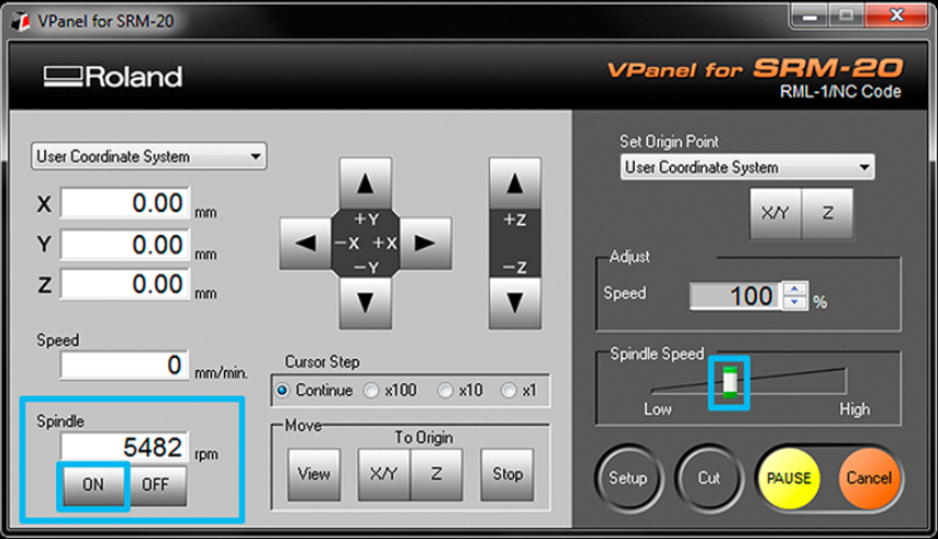
-
The next step is to position the machine using the X / Y and Z arrows on VPanel for
SRM-20
The values of the three coordinates were set to 0 to take advantage of the material
to make
the cut, in my case phenolic plate, to prevent the plate from moving, I fixed it
with
double-sided tape.
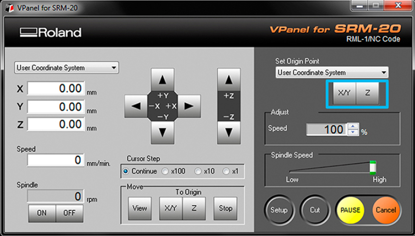
-
Material required for milling:
Material Required Cutting tool: 1/32 and 1/64. Fix on the milling machine to make the cut. Phenolic Copper Phenolic Plate. For card milling (manufacturing) Keys. To adjust the cutting tool. Double-sided tape. To fix the phenolic plate to the bed of the milling machine. Spatula. To remove phenolic plaque at the end of the cut. Sandpaper. Clean debris from the plate. -
Then you have to load the file with rml extension generated in the mod, for this you
must
click on the Cut button and add the file hello.ISP.44.traces.rml for the milling
machine
to start the cut, first you must load the trace and then repeat the process for the
milling
machine to cut the hello.ISP.44.rml board.
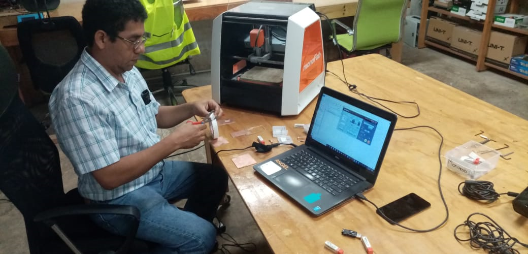
-
Finally the card were created.
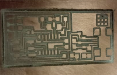
Now the process for the card trace is repeated.
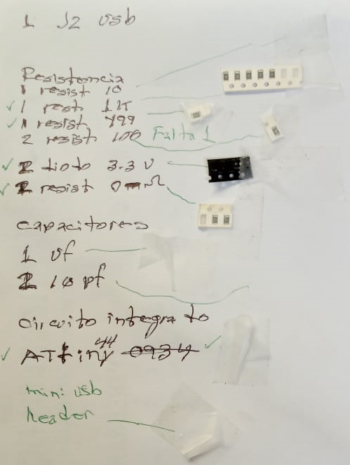
Components
These are the all the parts you need to build the board.
|
|
My electronic circuit.

Finally, in the FabLab of Yucatan they provided me with a usb component that I needed to
finish the circuit, this activity took a long time to finish because it was such small
parts, it was difficult for me to solder the components, then I connected the circuit to the
usb port of the computer and immediately felt like the ATTiny 44 microcontroller was heated,
apparently because of a short circuit, tests were carried out on the components and
apparently everything was fine, the solution was to change the microcontroller, however the
problem was not solved so I decided to make another electronic board and remove all the
pieces from the first to the second, this was because there were not enough components.
In the absence of 2 Resistor 100 ohm, in the FabLab Yucatan they told me to replace them
with the 2200 one, I don't know what will happen to my electronic board because I don't know
about it.
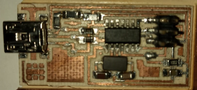
To solve the problem, the card was created again and I soldered each of the electronic
parts, now I felt with a better dexterity to solder, with this one, I made the plate 2
times.
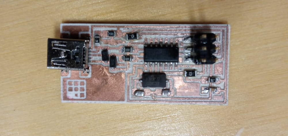
continuity tests
Now it is time to perform continuity tests on the electronic circuit, for this I use a multimeter. It seems that everything is going well here, there is something I do not like, reviewing the
circuit I see that some tracks are not well defined, apparently the blade I used in the mill
was already very used and that could damage the design, I hope this Do not cause a
malfunction.
For unknown reasons the plate did not work again, another one was manufactured, this time
for each piece that I was soldering, I was checking continuity, I hope this time it does
work. When testing the new board, everything seemed correct, but again it does not work, so the 2 zender diodes were exchanged for others with the same characteristic.
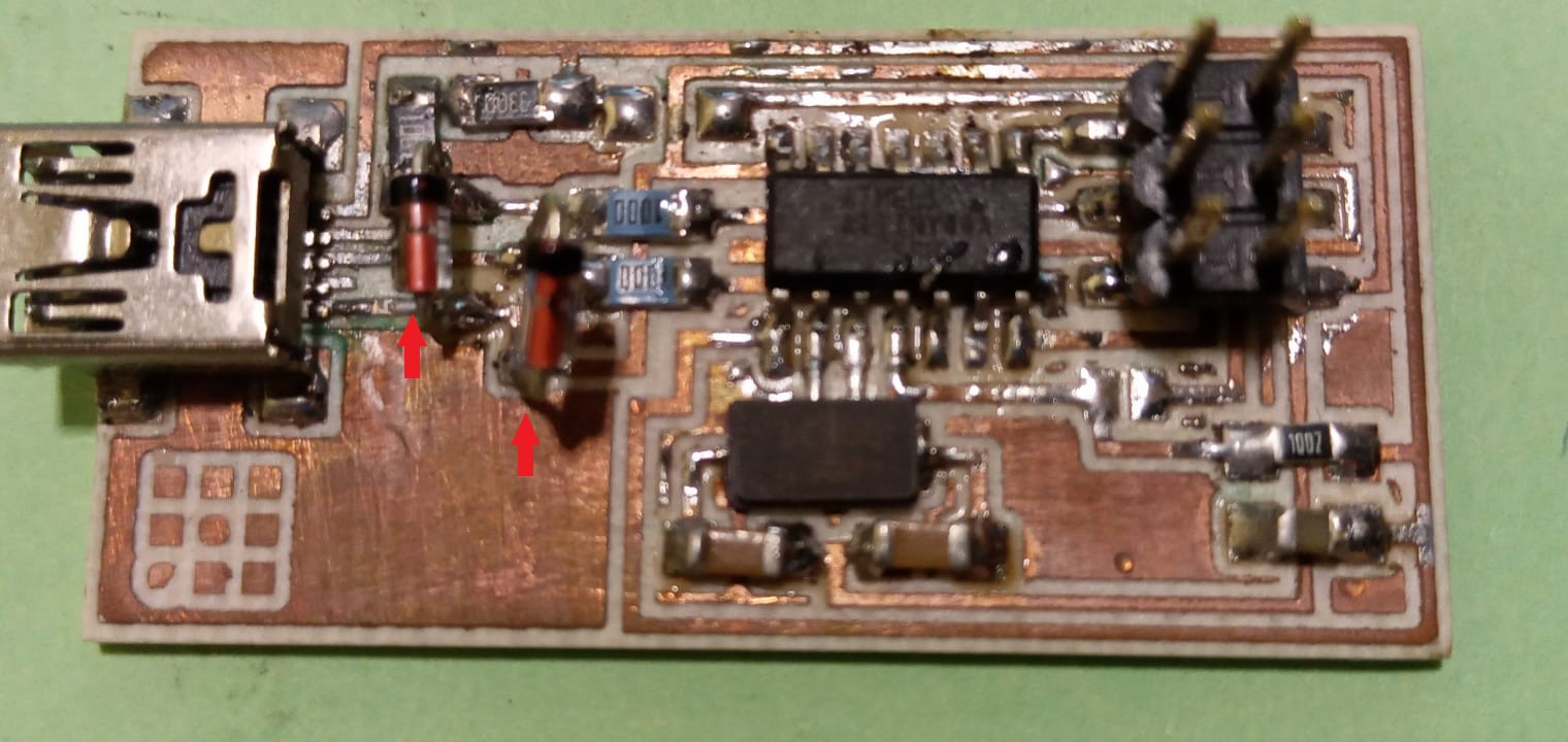
FabISP: Programming
Ubuntu Software Install
Get and install avrdude / GCC software and dependencies:
Open Terminal and type:
sudo apt-get install flex byacc bison gcc libusb-dev avrdudeThen type:
sudo apt-get install gcc-avr- type "y" when asked to do so by your system
Then type:
sudo apt-get install avr-libcThen type (may already be installed):
sudo apt-get install libc6-dev
Download and Unzip the Firmware:
Move to the desktop
cd ~/Desktop
Download the firmware from the Fab Academy Electronics Production page.
wget http://academy.cba.mit.edu/classes/embedded_programming/firmware.zip
Unzip the firmware
unzip firmware.zip
Edit
the Makefile
The Makefile is in the firmware directory that you downloaded. The
Makefile is set up to work with the AVRISP2 by default. If you are using another
programmer, you will need to edit the Makefile.
Ubuntu:
nano Makefile
Open your terminal / command line interface and move to the firmware directory.
Ubuntu / Windows type:
cd Desktop/firmware
For Mac users who downloaded the modified firmware:
cd Desktop/fabISP_mac.0.8.2_firmware
Next you need to compile the firmware.
Type:
make cleanIf you are successful - you will see this response from the system:
angel@ubuntu:~/fabISP_mac.0.8.2_firmware$ make cleanType:
rm -f main.hex main.lst main.obj main.cof main.list main.map main.eep.hex
main.elf *.o usbdrv/*.o main.s usbdrv/oddebug.s usbdrv/usbdrv.s
make hex
If you are successful - you will see this response from the system:
$ make hex
avr-gcc -Wall -Os -DF_CPU=20000000	 -Iusbdrv -I. -DDEBUG_LEVEL=0
-mmcu=attiny44 -c usbdrv/usbdrv.c -o usbdrv/usbdrv.o
avr-gcc -Wall -Os -DF_CPU=20000000	 -Iusbdrv -I. -DDEBUG_LEVEL=0
-mmcu=attiny44 -x assembler-with-cpp -c usbdrv/usbdrvasm.S -o usbdrv/usbdrvasm.o
avr-gcc -Wall -Os -DF_CPU=20000000	 -Iusbdrv -I. -DDEBUG_LEVEL=0
-mmcu=attiny44 -c usbdrv/oddebug.c -o usbdrv/oddebug.o
avr-gcc -Wall -Os -DF_CPU=20000000	 -Iusbdrv -I. -DDEBUG_LEVEL=0
-mmcu=attiny44 -c main.c -o main.o
avr-gcc -Wall -Os -DF_CPU=20000000	 -Iusbdrv -I. -DDEBUG_LEVEL=0
-mmcu=attiny44 -o main.elf usbdrv/usbdrv.o usbdrv/usbdrvasm.o usbdrv/oddebug.o
main.o
rm -f main.hex main.eep.hex
avr-objcopy -j .text -j .data -O ihex main.elf main.hex
avr-size main.hex
text	   data	    bss	    dec	    hex	filename
0	   2020	      0	   2020	    7e4	main.hex
In my case it sends me an error.

I do not know the cause of the error, perhaps because of the change in capacity of the 2 resistors of 100 by those of 2200.
Next, you need to set the fuses so your board will use the external clock (crystal)
Type:
make fuseAfter the make hex sent error, if this command worked and did not send any error.
angel@ubuntu:~/fabISP_mac.0.8.2_firmware$ make fuse
avrdude -c usbtiny -p attiny44  -U hfuse:w:0xDF:m -U lfuse:w:0xFF:m
avrdude: AVR device initialized and ready to accept instructions
Reading | ################################################## | 100% 0.01s
avrdude: Device signature = 0x1e9207 (probably t44)
avrdude: reading input file "0xDF"
avrdude: writing hfuse (1 bytes):
Writing | ################################################## | 100% 0.00s
avrdude: 1 bytes of hfuse written
avrdude: verifying hfuse memory against 0xDF:
avrdude: load data hfuse data from input file 0xDF:
avrdude: input file 0xDF contains 1 bytes
avrdude: reading on-chip hfuse data:
Reading | ################################################## | 100% 0.00s
avrdude: verifying ...
avrdude: 1 bytes of hfuse verified
avrdude: reading input file "0xFF"
avrdude: writing lfuse (1 bytes):
Writing | ################################################## | 100% 0.01s
avrdude: 1 bytes of lfuse written
avrdude: verifying lfuse memory against 0xFF:
avrdude: load data lfuse data from input file 0xFF:
avrdude: input file 0xFF contains 1 bytes
avrdude: reading on-chip lfuse data:
Reading | ################################################## | 100% 0.00s
avrdude: verifying ...
avrdude: 1 bytes of lfuse verified
avrdude: safemode: Fuses OK (E:FF, H:DF, L:FF)
avrdude done.  Thank you.
Next you want to program the board to be an ISP.
Then type:
make programIf you are successful - you will see the following response from the system.
 sudo make program
[sudo] password for user:
avrdude -c usbtiny -p attiny44  -U flash:w:main.hex:i
avrdude: AVR device initialized and ready to accept instructions
Reading | ################################################## | 100% 0.01s
avrdude: Device signature = 0x1e9207
avrdude: NOTE: FLASH memory has been specified, an erase cycle will be performed
         To disable this feature, specify the -D option.
avrdude: erasing chip
avrdude: reading input file "main.hex"
avrdude: writing flash (2020 bytes):
Writing | ################################################## | 100% 5.68s
avrdude: 2020 bytes of flash written
avrdude: verifying flash memory against main.hex:
avrdude: load data flash data from input file main.hex:
avrdude: input file main.hex contains 2020 bytes
avrdude: reading on-chip flash data:
Reading | ################################################## | 100% 3.36s
avrdude: verifying ...
avrdude: 2020 bytes of flash verified
avrdude: safemode: Fuses OK
avrdude done.  Thank you.
avrdude -c usbtiny -p attiny44  -U hfuse:w:0xDF:m -U lfuse:w:0xFF:m
avrdude: AVR device initialized and ready to accept instructions
Reading | ################################################## | 100% 0.01s
avrdude: Device signature = 0x1e9207
avrdude: reading input file "0xDF"
avrdude: writing hfuse (1 bytes):
Writing | ################################################## | 100% 0.00s
avrdude: 1 bytes of hfuse written
avrdude: verifying hfuse memory against 0xDF:
avrdude: load data hfuse data from input file 0xDF:
avrdude: input file 0xDF contains 1 bytes
avrdude: reading on-chip hfuse data:
Reading | ################################################## | 100% 0.00s
avrdude: verifying ...
avrdude: 1 bytes of hfuse verified
avrdude: reading input file "0xFF"
avrdude: writing lfuse (1 bytes):
Writing | ################################################## | 100% 0.00s
avrdude: 1 bytes of lfuse written
avrdude: verifying lfuse memory against 0xFF:
avrdude: load data lfuse data from input file 0xFF:
avrdude: input file 0xFF contains 1 bytes
avrdude: reading on-chip lfuse data:
Reading | ################################################## | 100% 0.00s
avrdude: verifying ...
avrdude: 1 bytes of lfuse verified
avrdude: safemode: Fuses OK
avrdude done.  Thank you.
It didn't work, I don't know the cause, since I don't have any other components I will have to buy others to make the circuit again.
angel@ubuntu:~/fabISP_mac.0.8.2_firmware$ make program
avrdude -c usbtiny -p attiny44  -U flash:w:main.hex:i -F -u -B32
 avrdude: Error: Could not find USBtiny device (0x1781/0xc9f)

avrdude done.  Thank you.
After trying to add code to the board in windows and Linux without success, it was done
using a mac laptop from instructor Oscar Díaz, it finally worked.
Not without first cutting the board again and soldering the components.
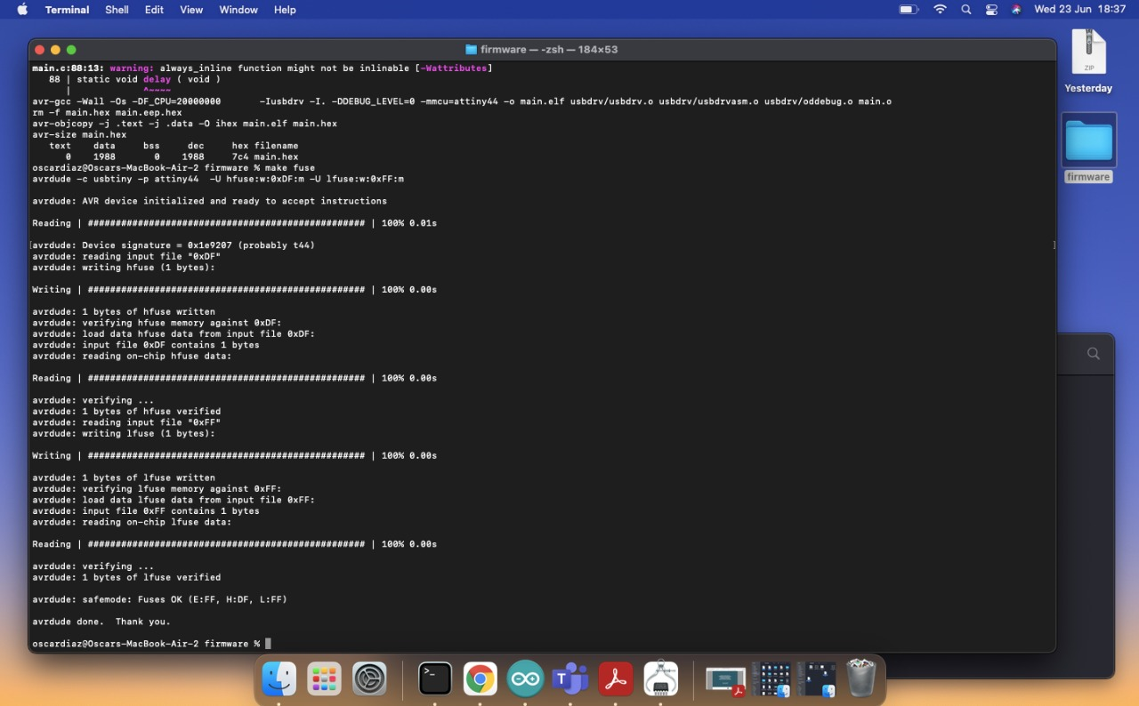
In this practice, 2 things happened, first I think one of the things for which it could not be programmed was due to damage to the diodes and second, the Windows 10 operating system.


