Introduction.
In this week I met and was able to make use of the scanner and 3d printing, I am really excited because for the first time in my life I could make use of a 3d printer, it is fabulous as by means of the computer-aided design object ideas can be materialized, it is required of course design knowledge but it is something that anyone can learn. I could make two 3d prints a sphere inside a cube and it was great.
Group assignment.
- test the design rules for your 3D printer(s)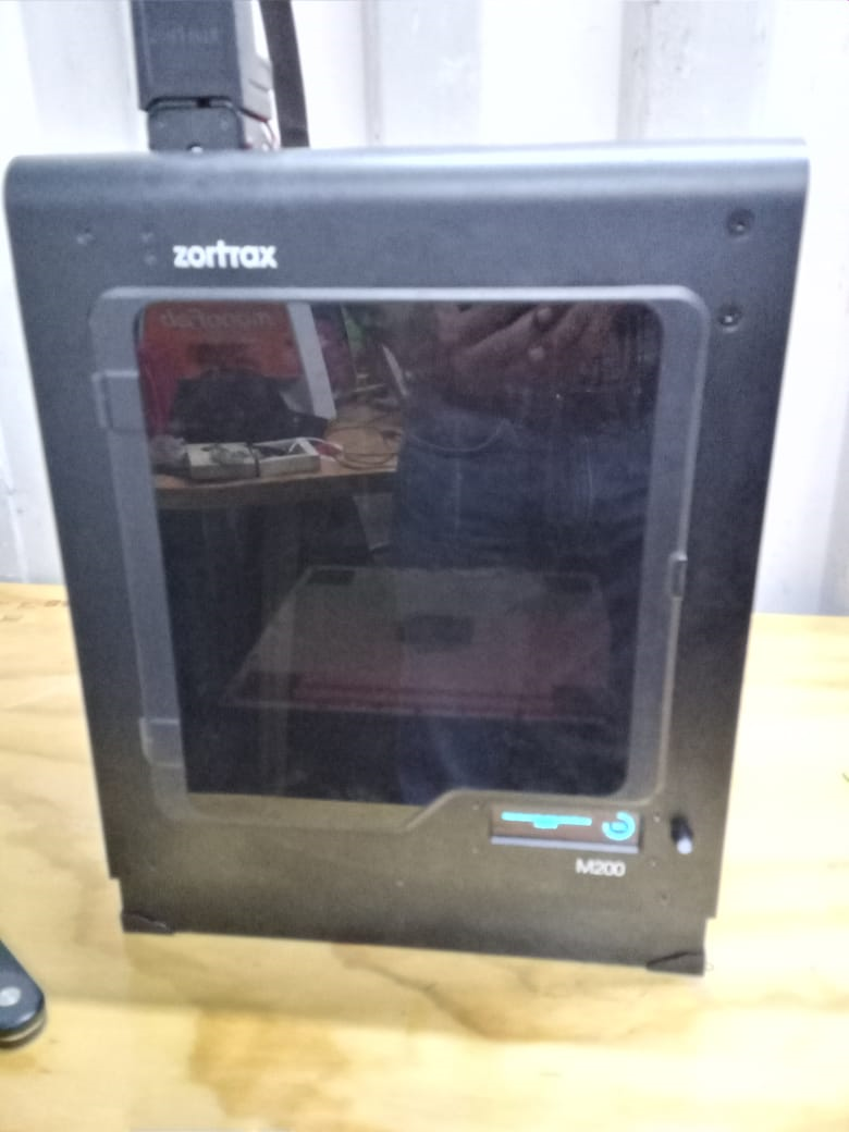
Zortrax 3D printers operate at high temperatures and have easily accessible movable
components,
therefore, you must be particularly careful when handling or operating the devices. While
operating
the printer, it is extremely important to avoid situations that may lead to burns or
interference in
proper functioning.
Do not leave the machine unattended during the print job - check it periodically for proper
functioning in order to avoid potential accidents or breakdowns. Turn off the printer once
the print job is finished.
Keep the printer away from heat sources, fire, flammable materials, humidity as well as
water and other liquids Place the machine away from any equipment emitting radiation.
All service and maintenance activities, as well as the operation of the device, require the
use of safety gloves included in the Starter Kit. It is also recommended to wear safety
gloves when removing the print.
A special room dedicated only to 3D printing is recommended and ensure adequate
ventilation in it. At the same time, it is not recommended to stay in a room where the 3D
printer has been used for a long time. Vapors released during the printing process do not
represent a direct hazard, but they can have negative effects when combined with long-term
accumulated dust particles.
Specification for Zortrax M200
Device
Software
Printing
Temperature
Electric specifications
Installation
Some key steps to start printing with ABS is the correct installation of a thermal plate that prevents its movement using perforated plates, this guarantees a perfect maintenance of the models during printing. Installation is easy, it has magnetic points that are intuitively inserted into the plate. With two connectors they allow the calibration and heating of the tray, these remain visible and must be handled with care, with the time of use we will know if it is a point in favor against after printing several objects. Do not forget about the `protection: gloves, glasses supplied by Zotrax.Then you just have to insert the reel support and guide the cable that feeds the print head, as well as the filament guide that will allow the ABS-Z to reach the extruder. Now you simply have to connect your printer to a power source and press ON.
Software
Z-suite, the brand's software, has a simple and intuitive interface. Only manufacturers and strong supporters of Open Source can be a bit disappointed. Because it can do almost everything ...Among its conventional options is to add, delete, view, flip the model, move, rotate, scale automatically. Something new within the applications is the cut, not the slicage, it really serves to cut the pieces of the pattern to help remove the supports or print larger pieces. This function offers many possibilities that make the task easier if you need to use other software.
In printing, the fundamental thing is: coil type, layer thickness (there are 5 options), speed (2 options), recharge (4 options), fan percentage and, finally, being able to choose the angle at which they will be placed. the supports and the volume they will have. Within the Zortrax M200 software there are also some advanced settings available. Like the location of the seam, where you can choose the same point or do it randomly. This allows you to eliminate the unsightly line on the back of prints when the layer always starts in the same place.
For testing I use the # 3DBenchy model
provided in STL file format, which is an industry
standard for 3D printing. This surface tessellation language describes and represents the
surface of a computer generated object (CAD file).
An STL file is a shrink wrap representation of a 3D model, covering its surface with many
small triangles. # 3DBenchy's high-resolution STL file has exactly 225,154 triangles that
cover the shape of the ship and deviate less than one thousandth of a millimeter (0.00003937
inches).
The # 3DBenchy.stl file is designed and QA for 3D printing. Its topology is 100% waterproof
and does not contain mesh errors such as collector areas, inverted normals, holes, etc.
STL files can be saved in ASCII or binary format. To save disk space, the # 3DBenchy.stl is
provided as an 11.3 MB binary file.
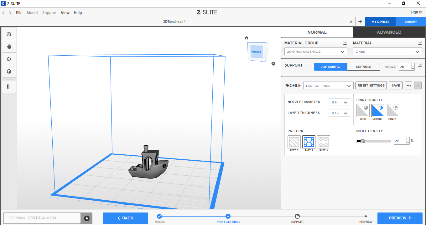
Every 3D-printing process can be varied to yield different results regarding printing-speed, layer height, surface smoothness, material consumption, etc. In most tests #3DBenchy has been printed according to the following generic settings for extrusion-based 3D printers (FFF).
- Scale: 1:1 (unmodified in size, from bow to stern #3DBenchy.stl measures 60.00 mm).
- Layer height: 0,2 mm
- Infill: 10%
- Print speed (extrusion): up to 50 mm/s
- Print speed (travel): up to 150 mm/s
- Print nozzle diameter: 0,4 mm
Calibration
The Zortrax M200 calibration is semi-automatic, 5 colored squares serve as calibration zones. When you start leveling, the machine takes over, and after many twists and turns it gets close to the print head with the required distance from the heating plate. If it is too close or too far, the printer prompts you to tighten or loosen a screw present at the bottom of the plate, after which the automatic calibration restarts.individual assignment
- design and 3D print an object (small, few cm3, limited by printer time) that could not be made subtractively
Considering that the design should not be able to be created using another type of technology, such as laser cutting or cnc cutting, I thought of designing a cube and putting a sphere inside it, those cuts in the corners of the cube I think can not be done another way, only with 3d printing.First I create a sketch. Second in the create menu, select rectangue-> center rectangle.
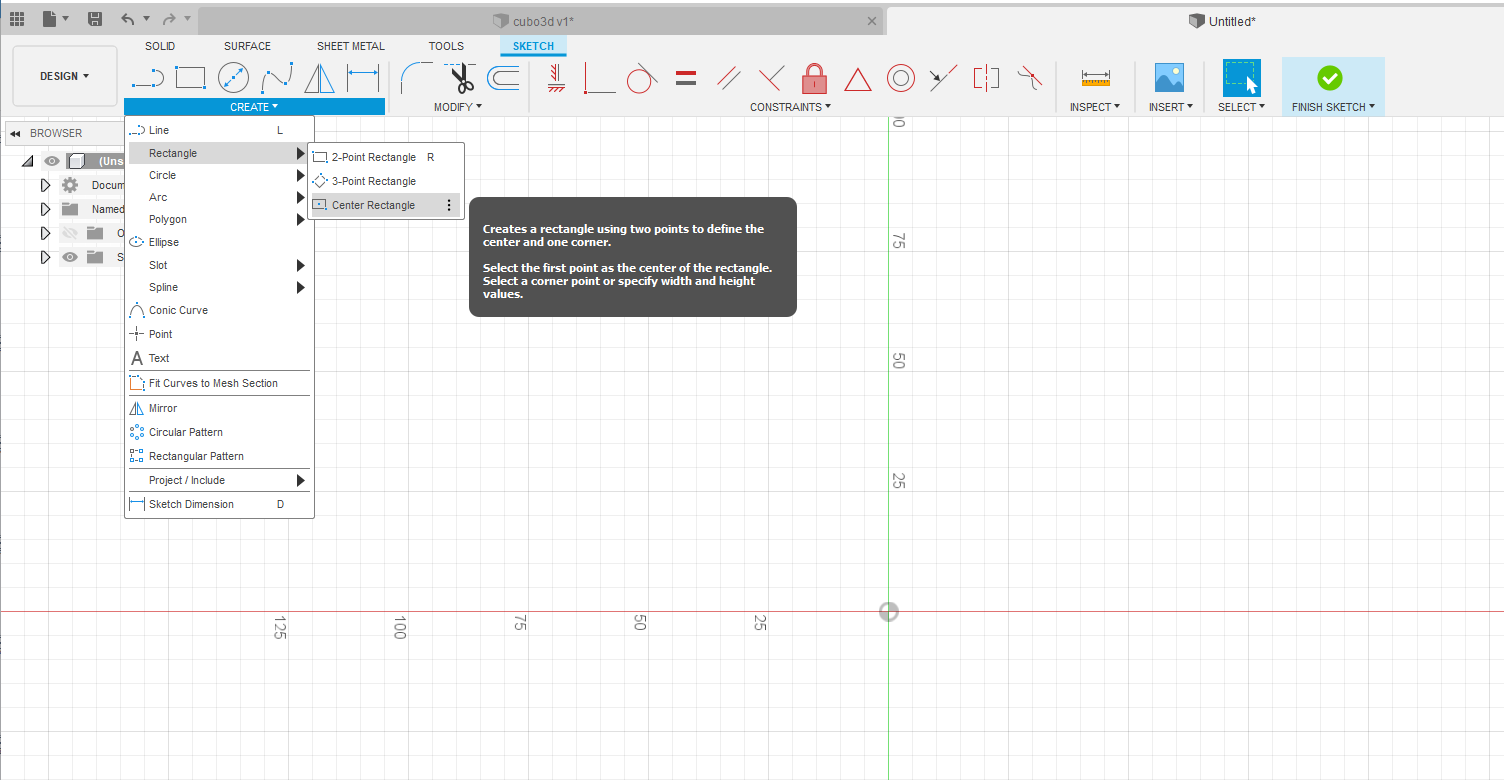
Third gave square measurements and I click finish sketch.
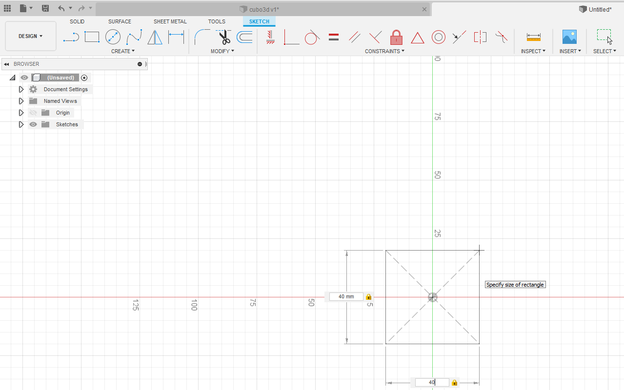 Fourth I selected the 2d image and pressed the e key and gave it 40 mm height (z).
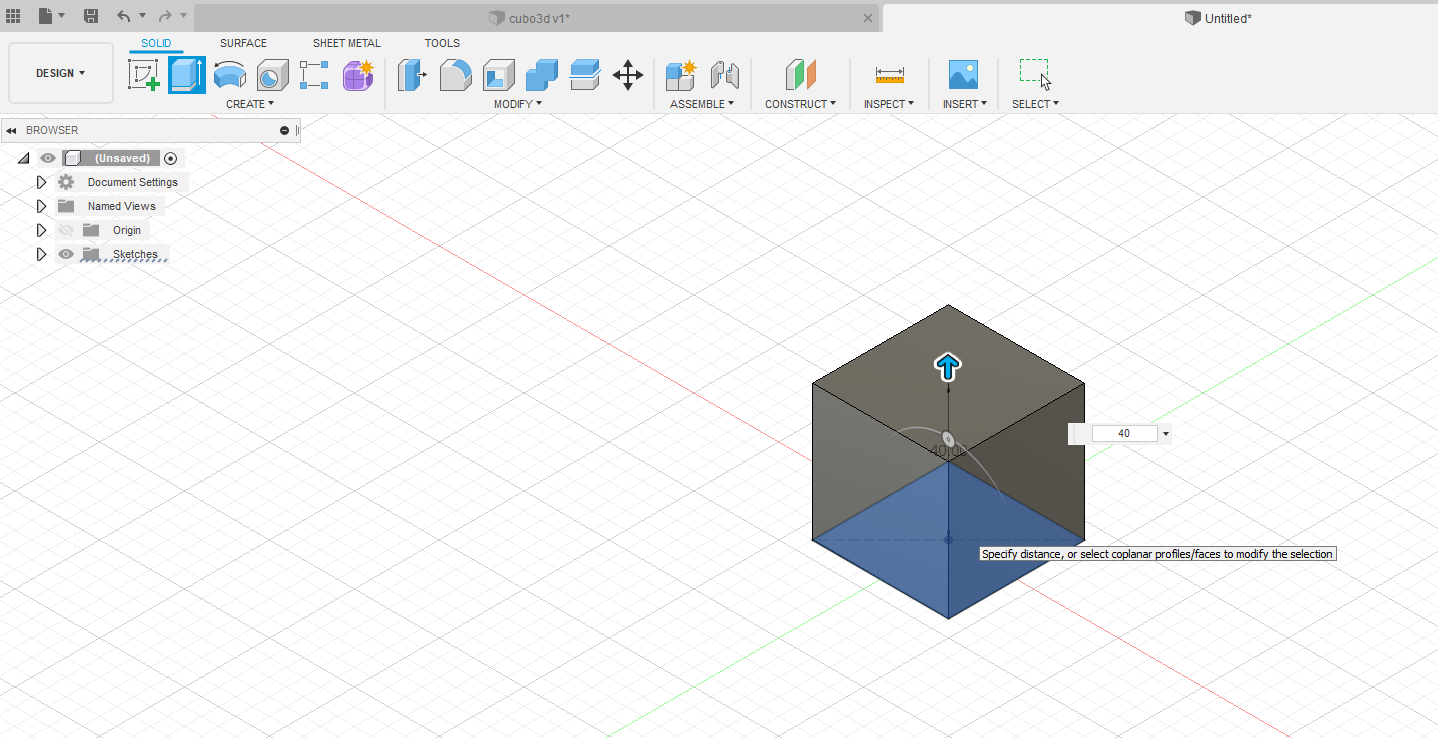 Fifth he selected the upper face and added another sketch and designed another centered
rectangle of 30x30 mm and I click finish sketch.
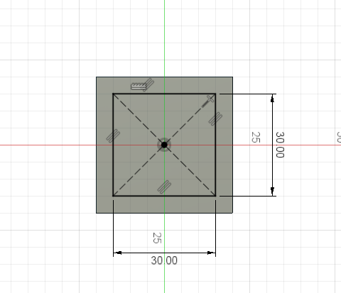 Sixth he selected the 2d image and pressed the e key and gave it -35 mm height (z) and a
cube is created.
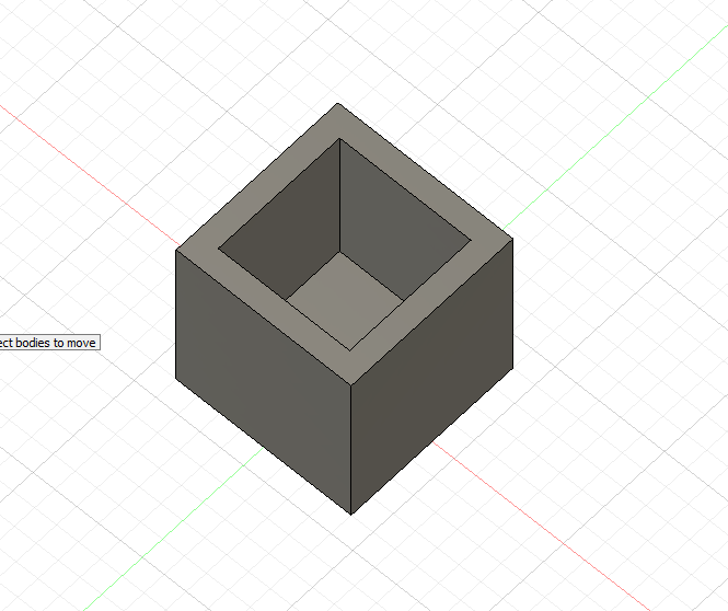 Seventh. I create a sphere.
 Eighth select new body and give dimension 30 mm, press the m key after selecting
Body2, to move the sphere
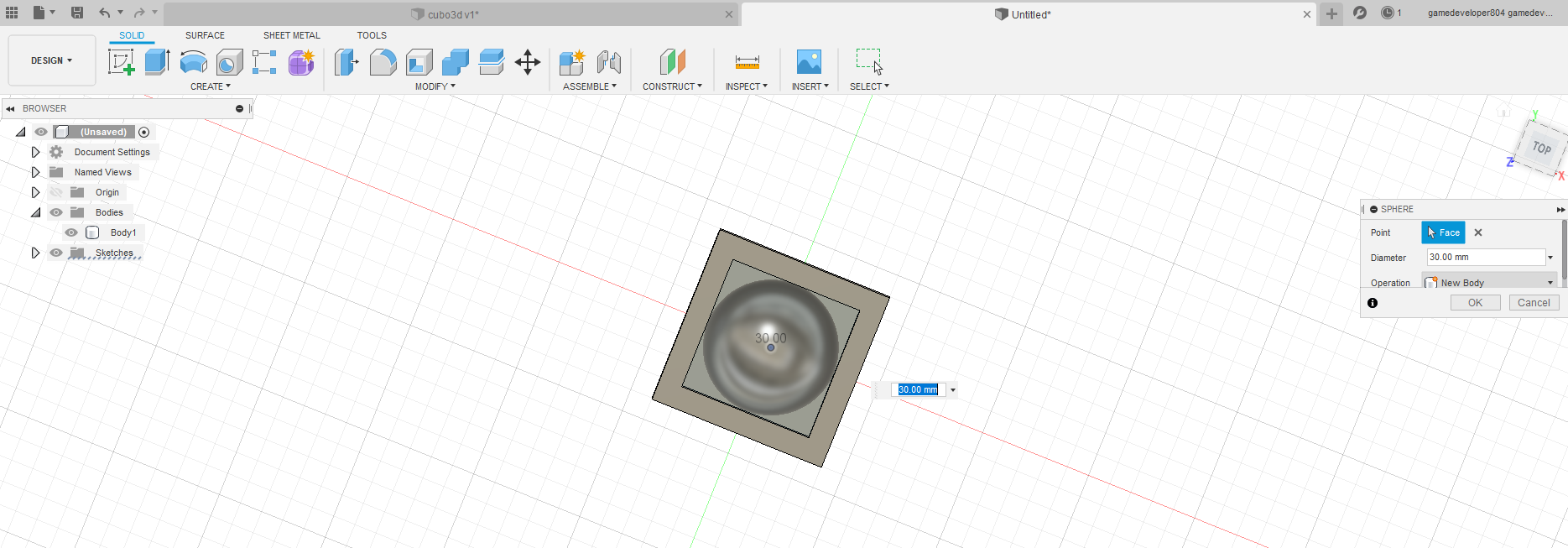 Once the sphere is placed in the right place, select the two Body and in menu modify select.
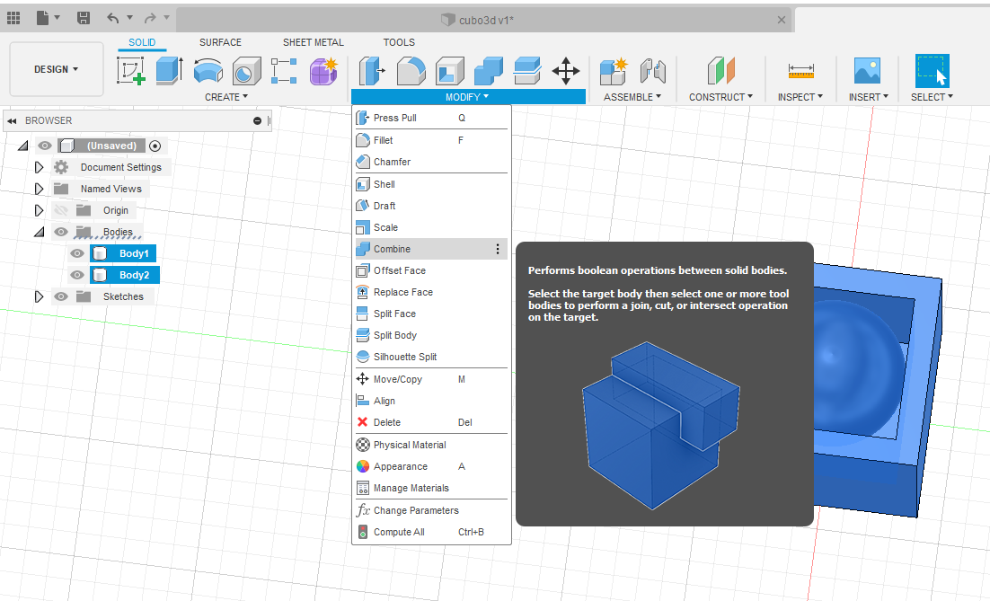 The design of the 3d image is finished, save the file.
The 3d design consists of a sphere contained within a cube, the space that remains of the circular parts of the sphere on the walls of the cube, I think it would not be possible to do it by subtraction.
 The next step is to prepare the image for printing, for which the body is selected, right click
and select Save as STL.
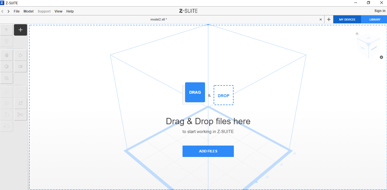
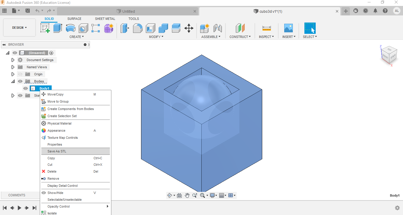 Now you have to open the z-suite software of the 3d printer which was previously installed.
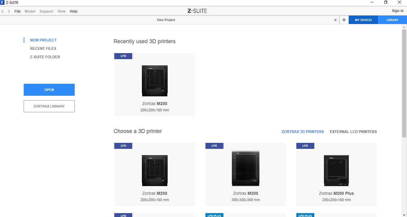 For this case I am going to use the M200 model, so on that model you have to click on start a
new project.
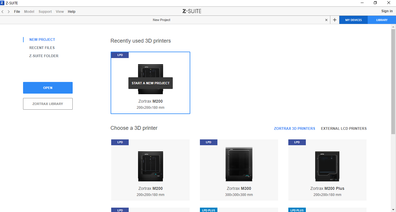 Now the software is ready for us to load the STL file, this can be done by dragging and dropping
the model.
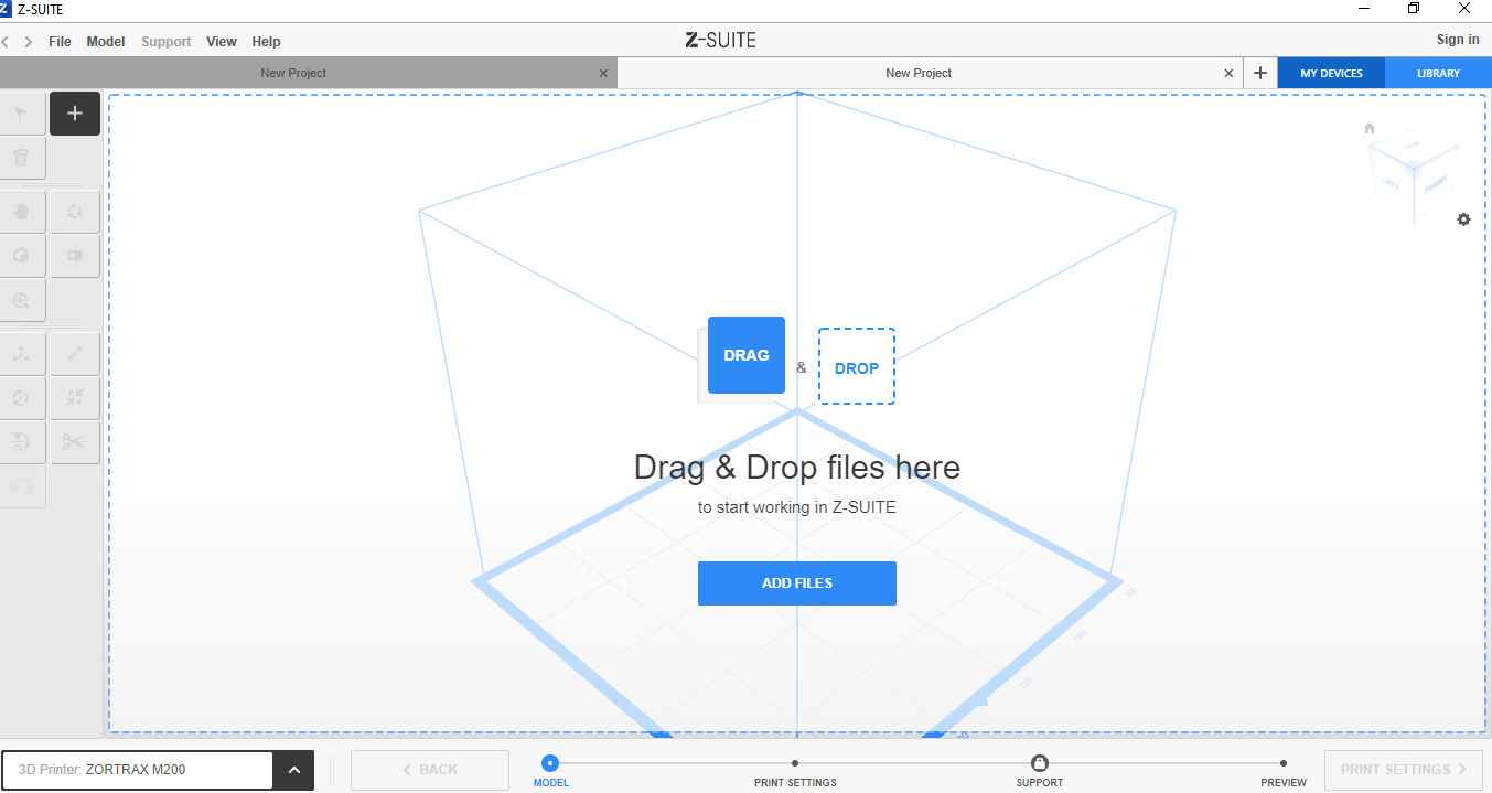 The other way to add the model is by clicking on the add files button, this opens a window to
select the file.
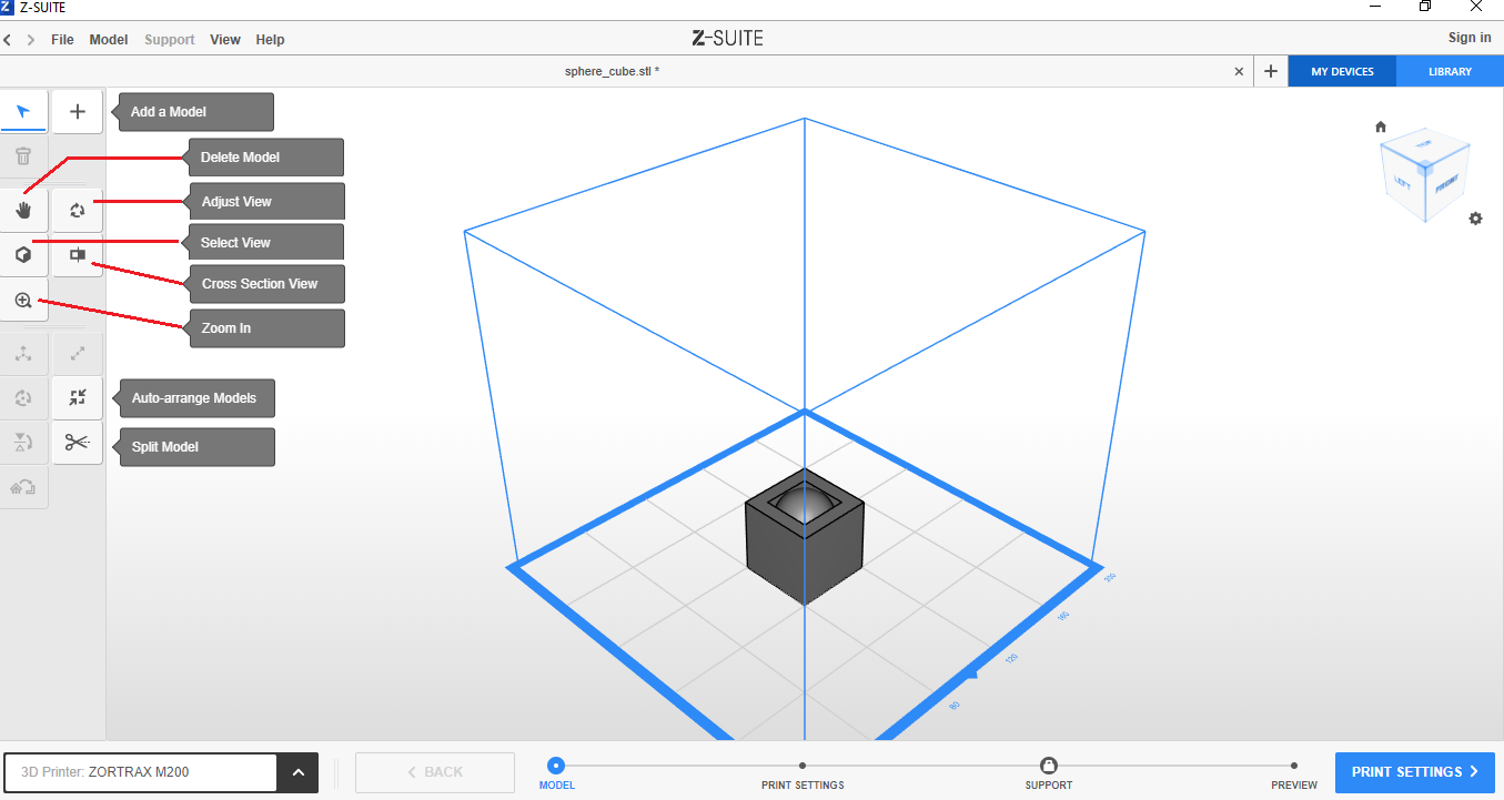
 Model loaded in z-suite.
As you can see in the left panel there are several options that allow, among other things, to add another model, apply zoom, it is a matter of testing what each one does.
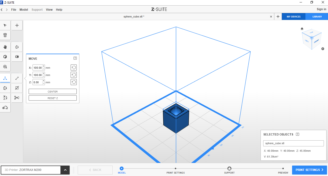
 Clicking on the image shows the position of is in the x, y, z axes, to change that position in
any axis you just have to increase (+) or reduce (-) the number.
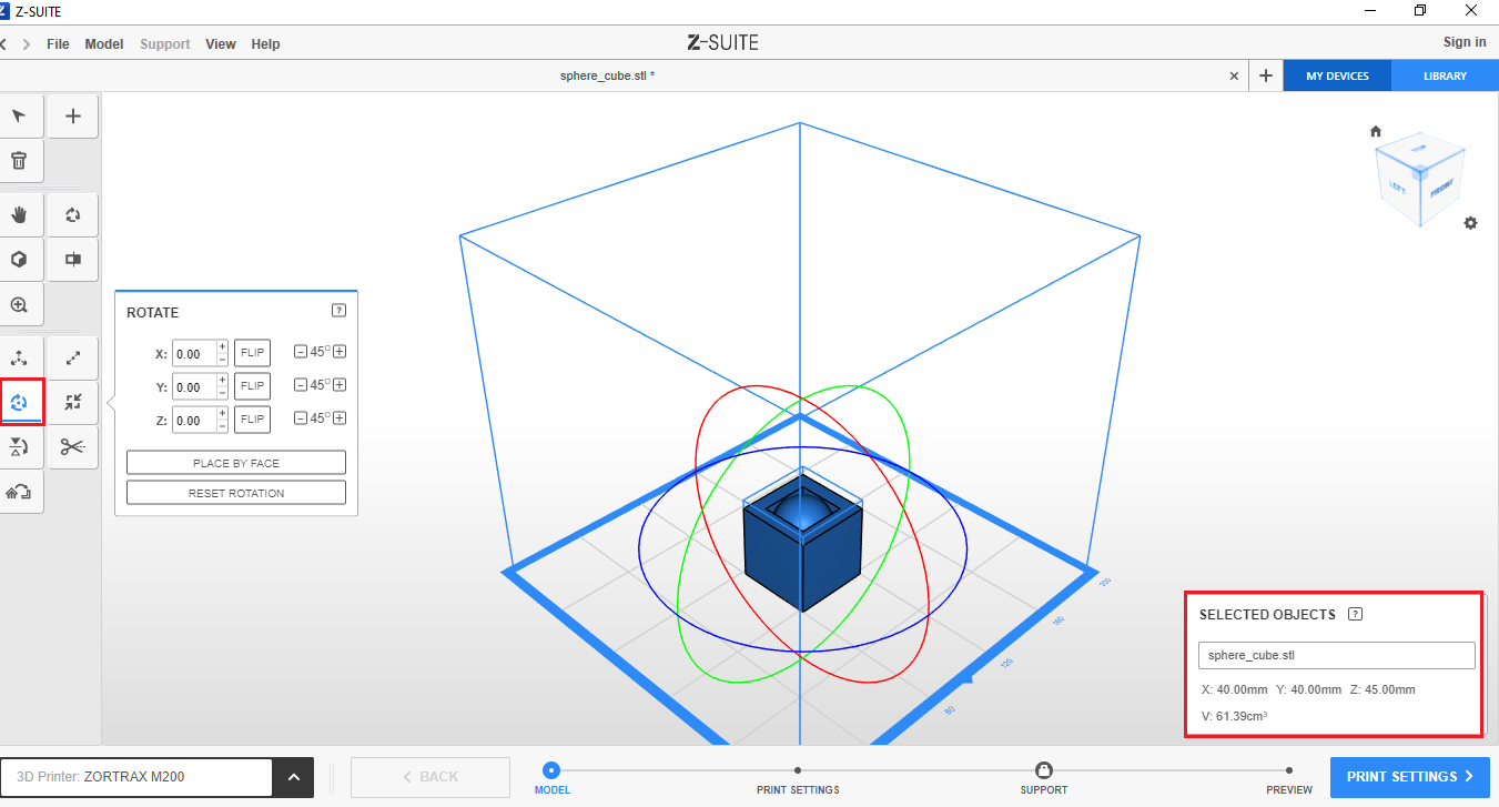
 If you need to rotate the model, you must first select and then click on rotate model, then you
must increase (+) or reduce (-) the value of the axis or angle, on the required axis, in the
same way you can do it using the mouse.
When the model is selected, you can see the size of each axis.
 It is time to set the print settings, for this you have to click on the button located in the
lower right part of the canvas.
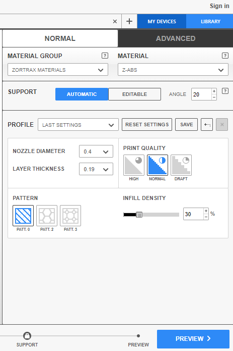
 Here, you choose the type of material, support (when the shape of the object runs the risk that
the printing will fall when advanced) automatic or editable, profile, nozzle diameter, layer
thickness, print quality, pattern, filling density. I believe that these values should be tested
to learn to establish them accurately.
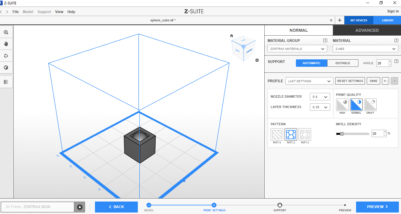 After setting these parameters, click the preview button, after a few seconds the computer
estimates the time.
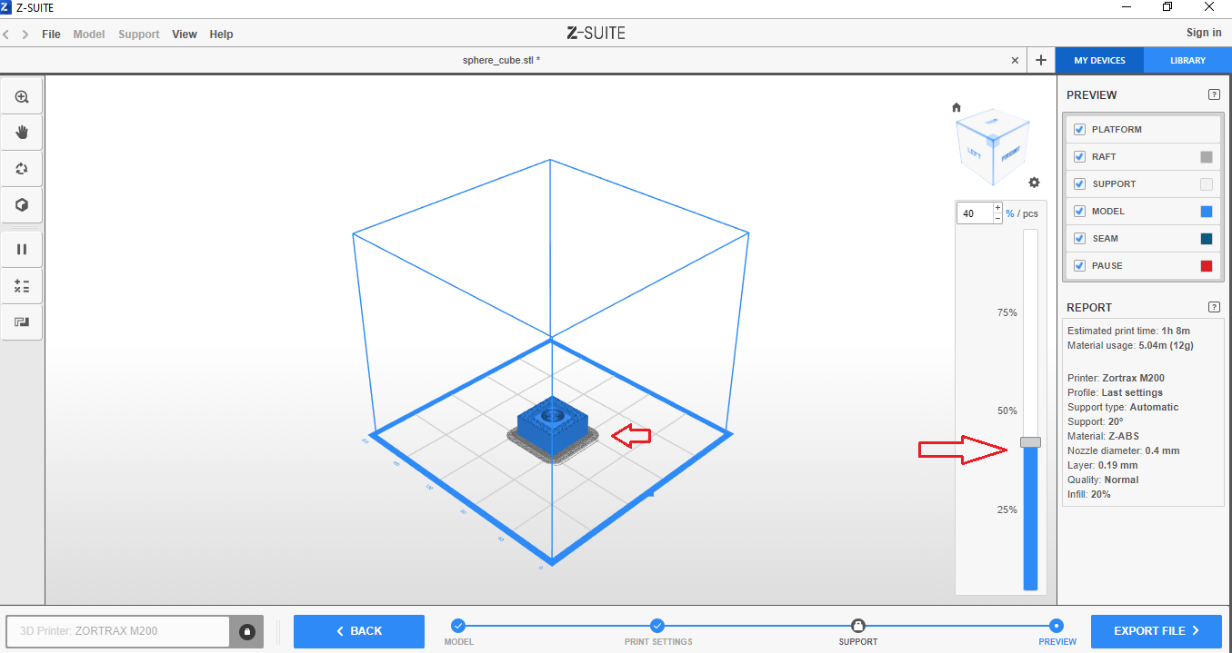
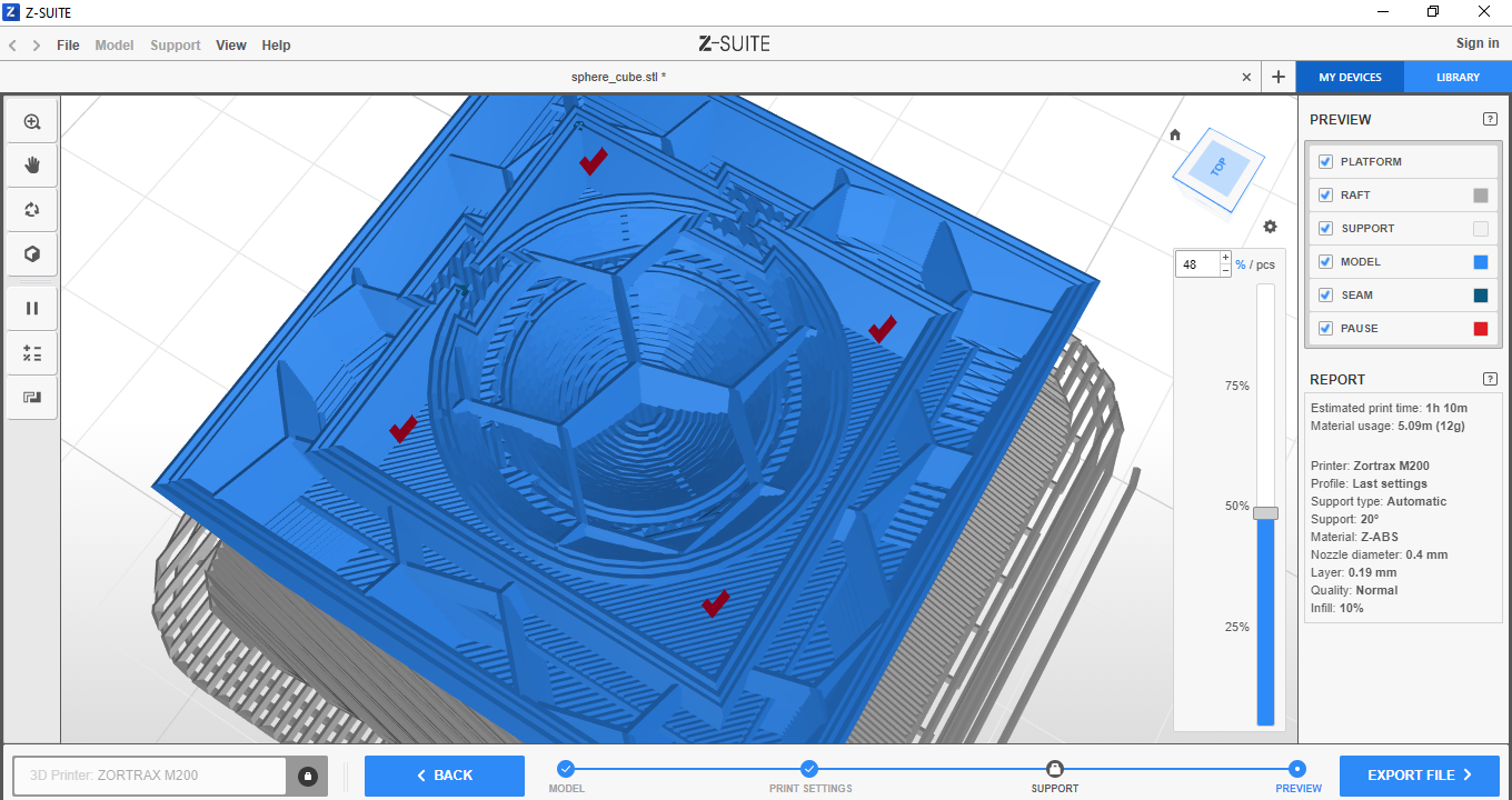
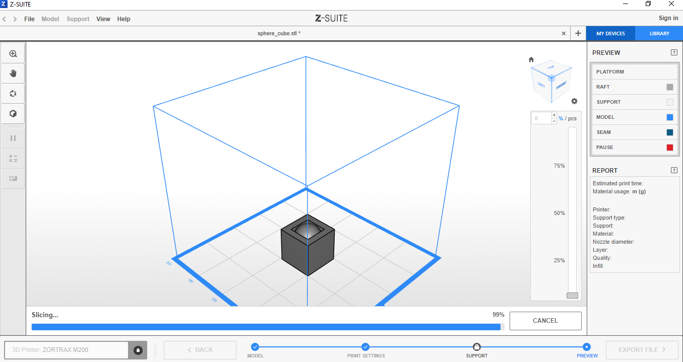 With the mouse move the vertical bar to observe the previous printing process, the first thing
that prints is the support on the printer bed.
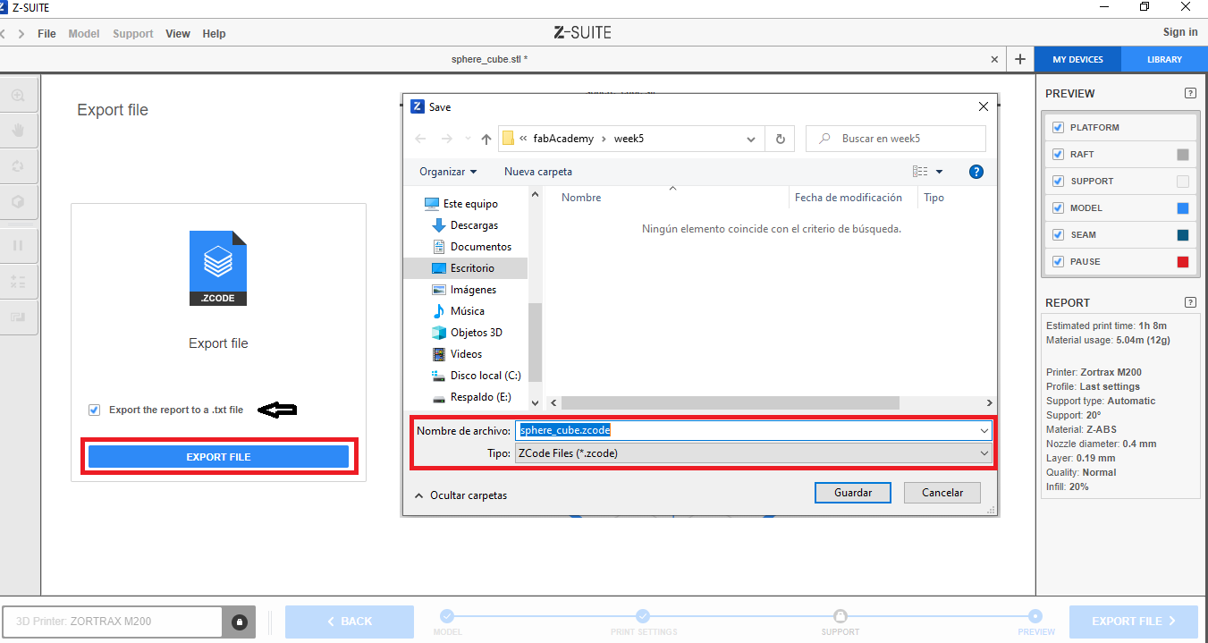
 Click on the export file button. It will show something like this. Clicking on export file again
shows a window to name the file and choose the folder where it will be saved.
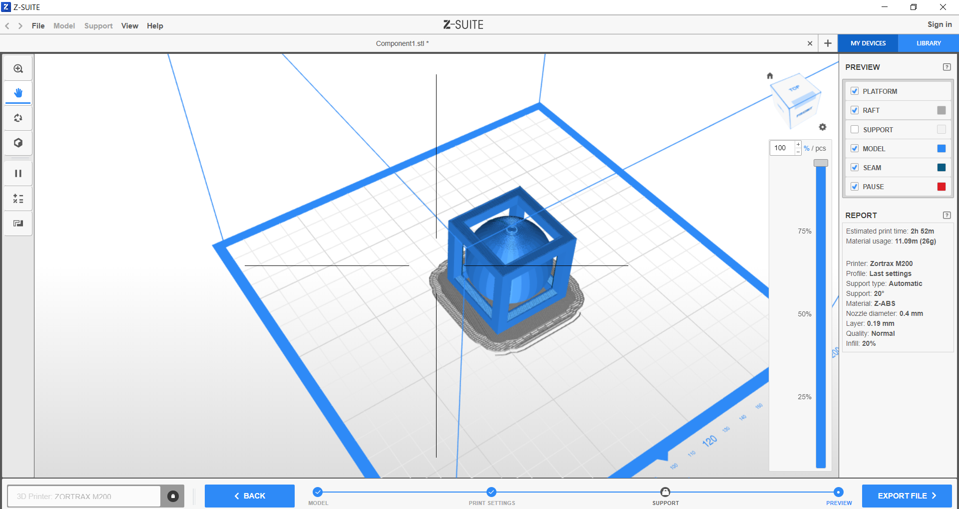
 In the software preview, you can see how empty spaces are left between the cube and the sphere,
this is due to the curve that is formed as the additive manufacturing process advances, these
spaces are inside at each corner , I think it would be difficult to do it with another type of
manufacturing. As the sphere becomes larger, the space between it and the cube is smaller. So at
the bottom of the cube, the gap is larger.
That file is now copied to a memory to be later inserted into the printer to select the file and start printing.
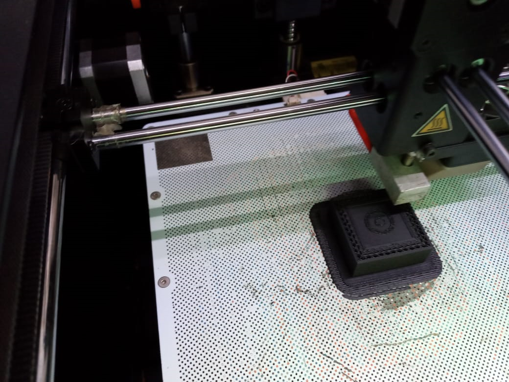 After a long wait, I finally see my design materialized, it is the first time in my life that I
make a 3d printing and it is very satisfactory for me, because I see the importance of choosing
the x-coordinates during the design phase. , and, as well as measurements.
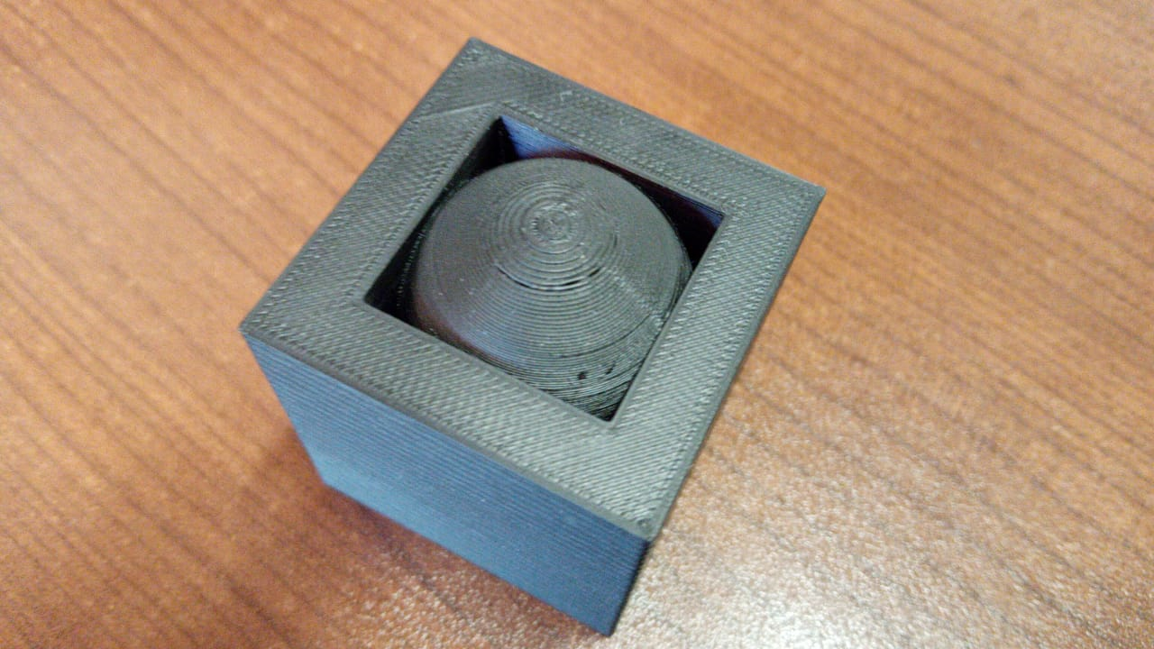
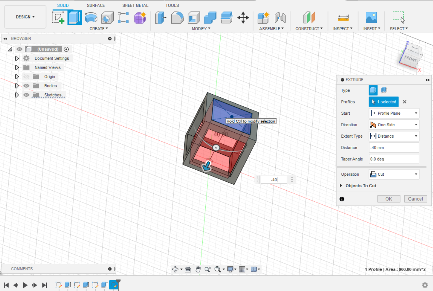
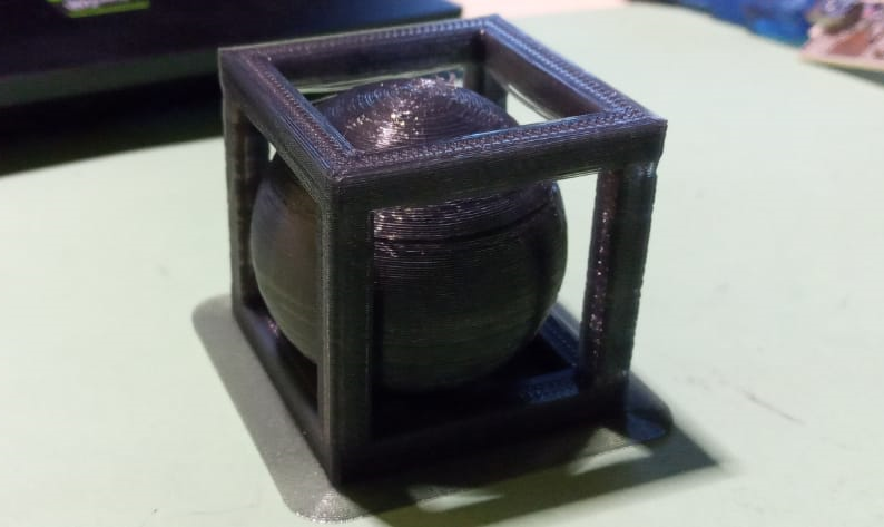
As the sphere is not visible, I am going to redesign the cube but now without walls, only the outline so that the interior can be appreciated.
Extrude the first face
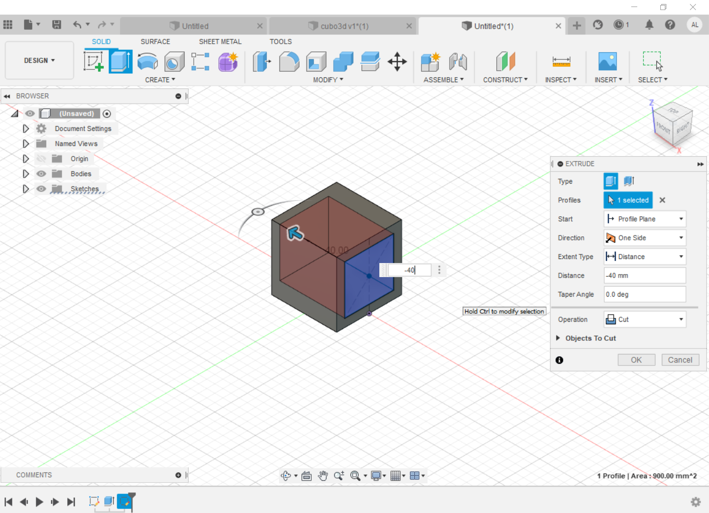
Extrude the second face
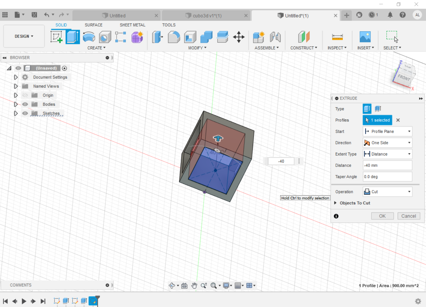
Extrude the third face
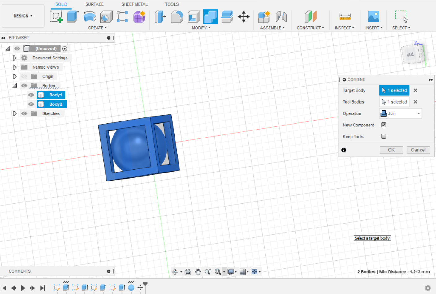
I add the sphere and placed it inside the cube (press the letter m), then I selected the 2 sketches and with the combine tool I integrate them as an object.
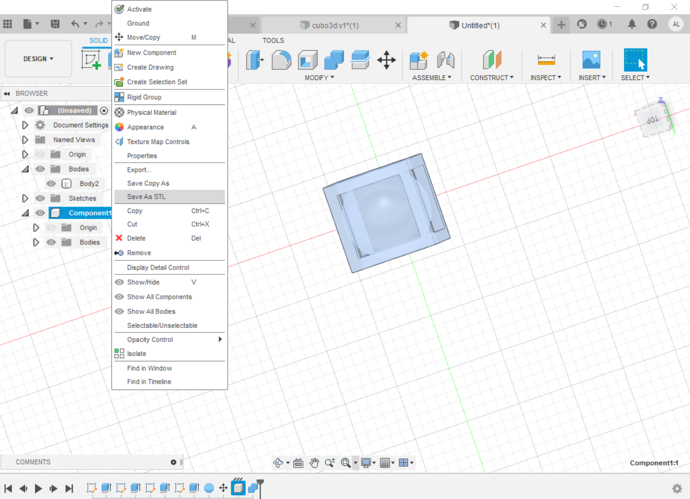
Now I'm going to save the object in STL format, to print it.
Open the z-suite software again and carry out the steps previously described to send the cube to print again.
The print is ready, same design same size, but the cube is now open.
- 3D scan an object (and optionally print it)
To start the 3d scan it is first necessary to download the skanet software To do the 3d scan use the kinect for this reason the software is downloaded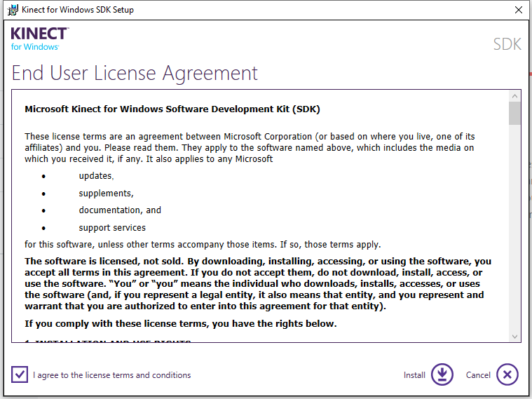 At the end of the installation a window appears, in which you must click on Download the
develper toolkit.
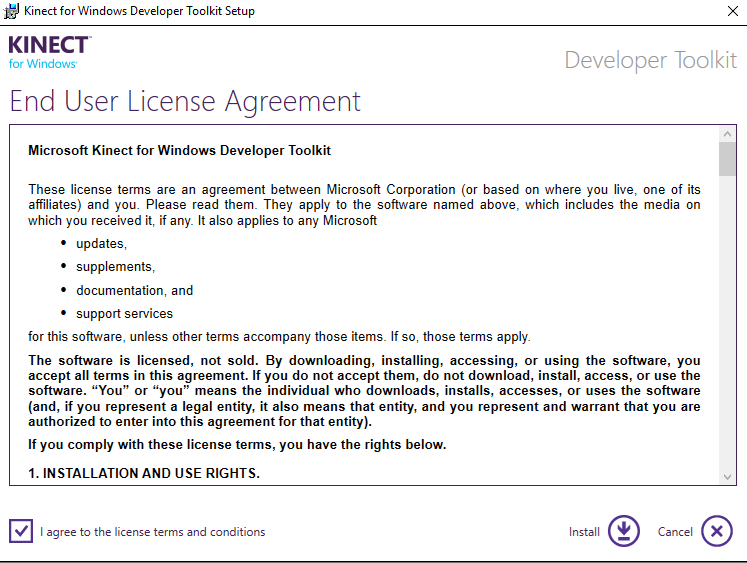
 At the end of the installation a window appears, in which you must click on Download the
develper toolkit, Open the official page Kinect for Windows
Developer Toolkit
 The second step is to install the skanect software.
Once installed, open the previously installed software "developer toolkit brower 1.8.0", the
kinect only works as a 3d scanner with that version.

Select sampleC # and in kinect fusion Explorer-WPF click on run, this action opens a window where the image that is being captured by the kicnet appears. Select sampleC # and in kinect fusion Explorer-WPF click on run, this action opens a window where the image that is being captured by the kicnet appears. With this a test is performed to see if it detects the kicnet.
 After having performed the kinect recognition test by the software, my scanning task begins, for
this we proceeded to run the Skanect application.
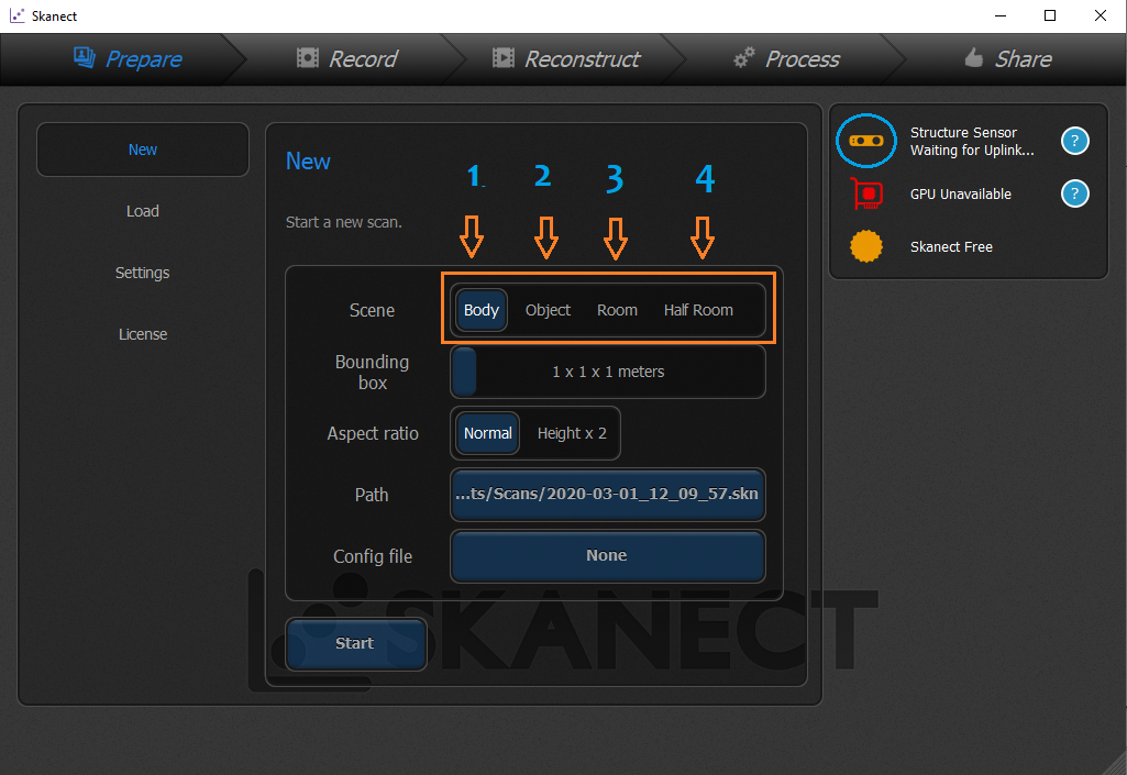 In the image it is observed that there are 4 ways to create the scene, (it is
numbered from 1 to 4) and the choice will depend on what I want to do in my case I
chose body because it is my own, to know the differences I suggest doing try the 4 options.
Once the sensor is recognized, the image capture must be started (record), this step requires a lot of patience, the first scan was done with the help of two people, the software operator and the one that moved around me With the kinect in his hands.
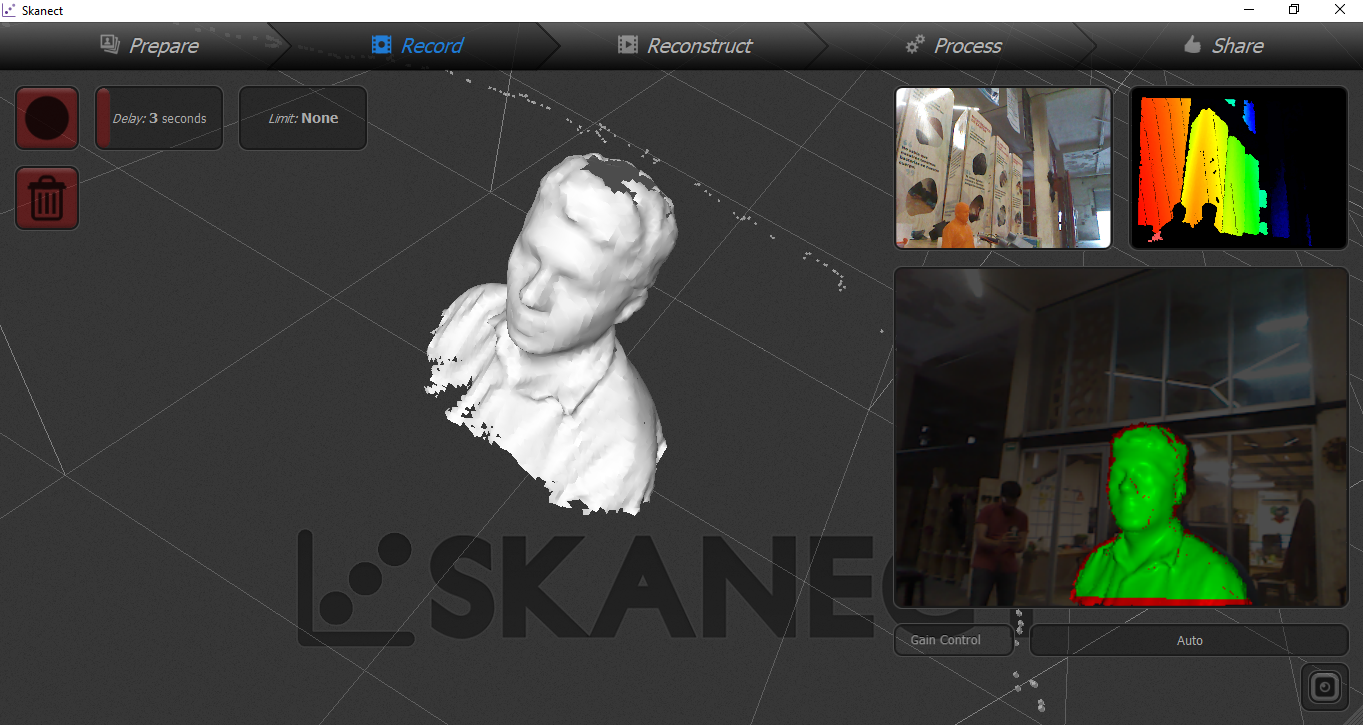
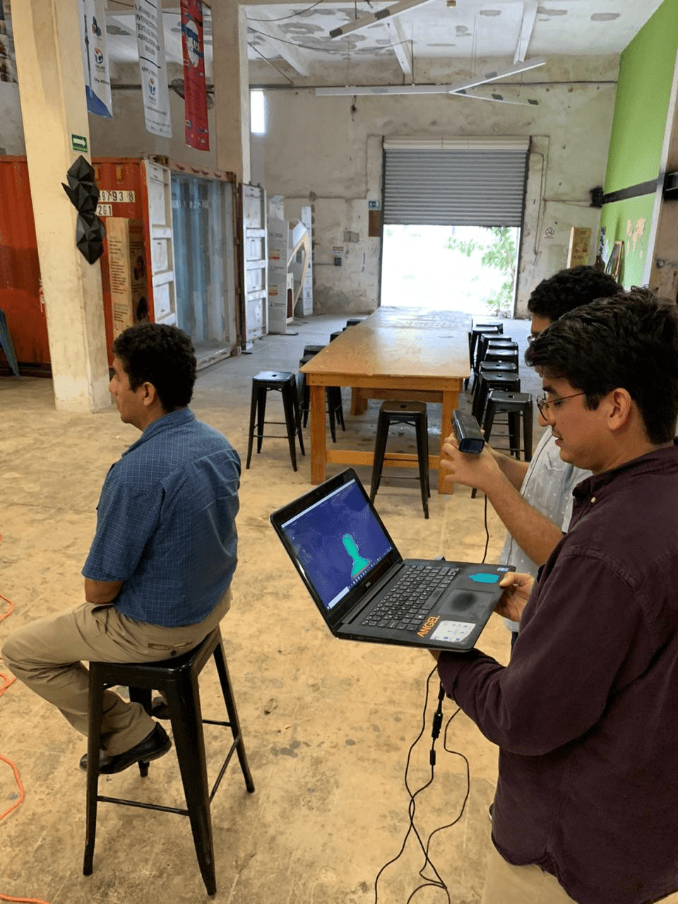 The quality of the 3d image was not of good quality, at the top of the head a perforation
appeared, this may be because when moving the kinect the angle of the image was constantly
changing.
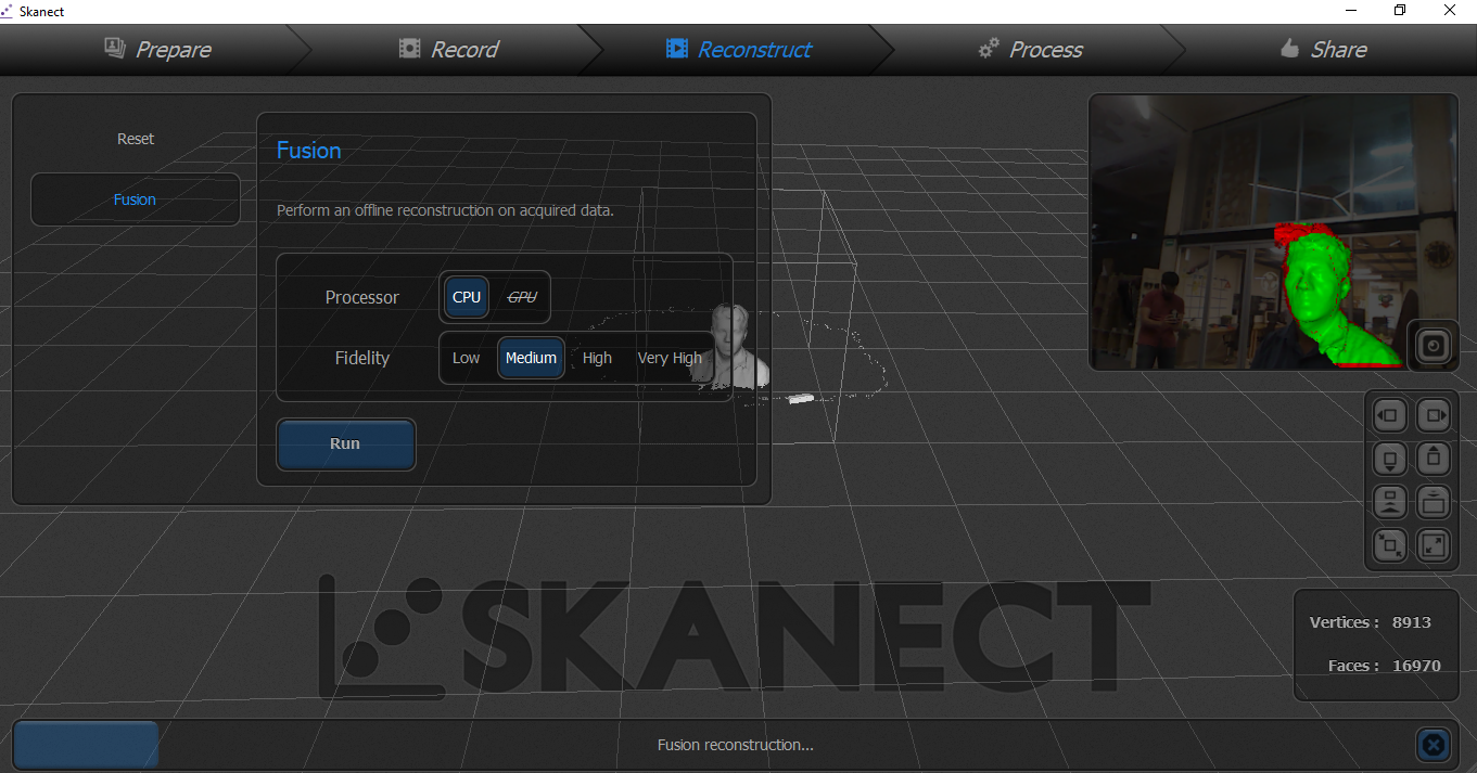
 The software has the option of image reconstruction, I used all the blending options, but the
quality of the 3d image did not improve.
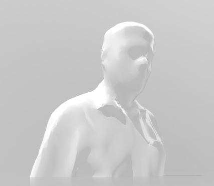
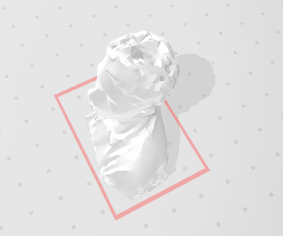 I decided to do a second 3d scan but now instead of moving the kinect, I made the rotating
movement, this allowed the image to be more uniform without so many imperfections.
 Finally in the software I used the option to process to change the height of the image and crop
it.
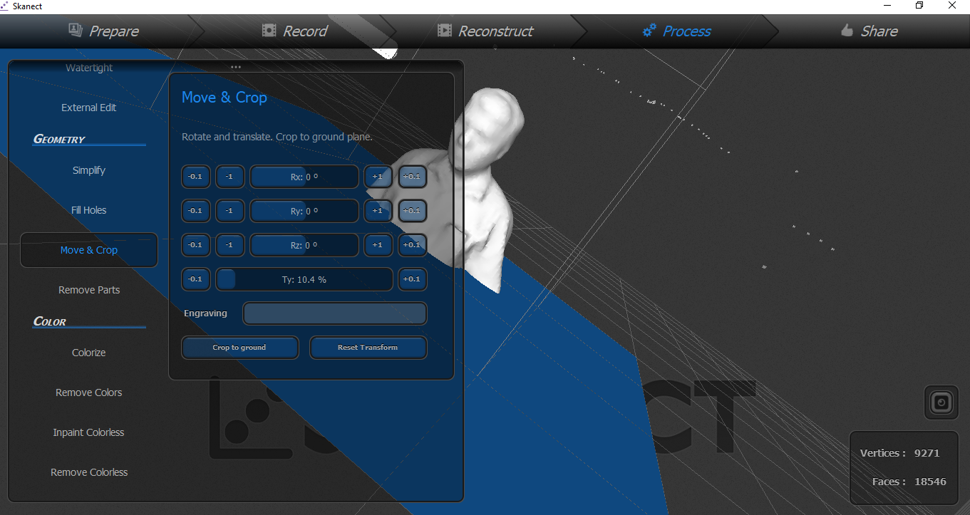 I saved the image with stl format, there are other formats.
This activity made me very interesting and fun and to finish the job I decided to do the 3d
printing, for this I opened the z-suite software and selected the zortrax m200 printer, this is
done to prepare the file requires the printer.
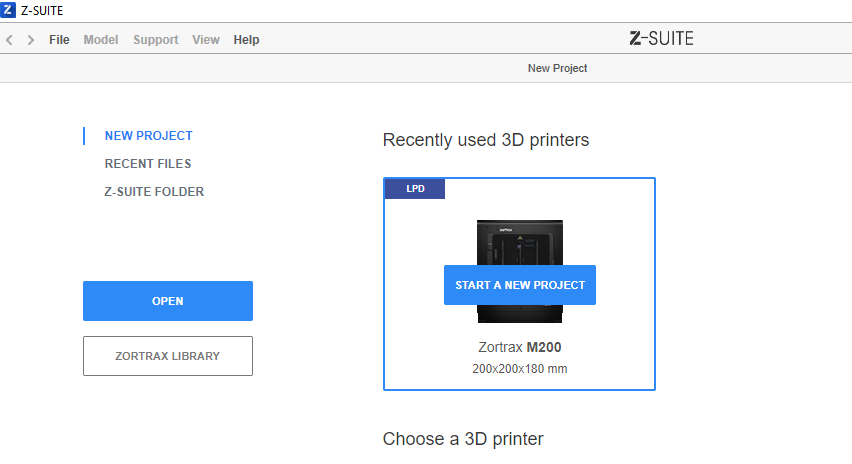 The next step is to add the file that was saved after the 3d scan.
 Because the image is larger than the print dimensions, it is necessary to reduce its size.
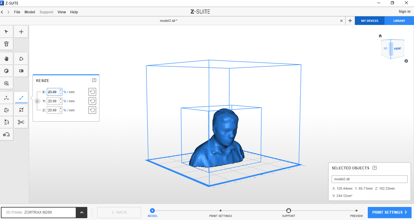
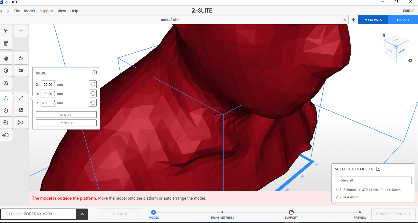 Because the image is larger than the print dimensions, it is necessary to reduce its size. In
this step the size of the printed 3D image will be determined.
 After setting the image size, print settings must be selected.
 Clicking on preview, this requires waiting because the computer is processing the image, if
necessary the software creates a support print to prevent the image from deforming during the
printing process.
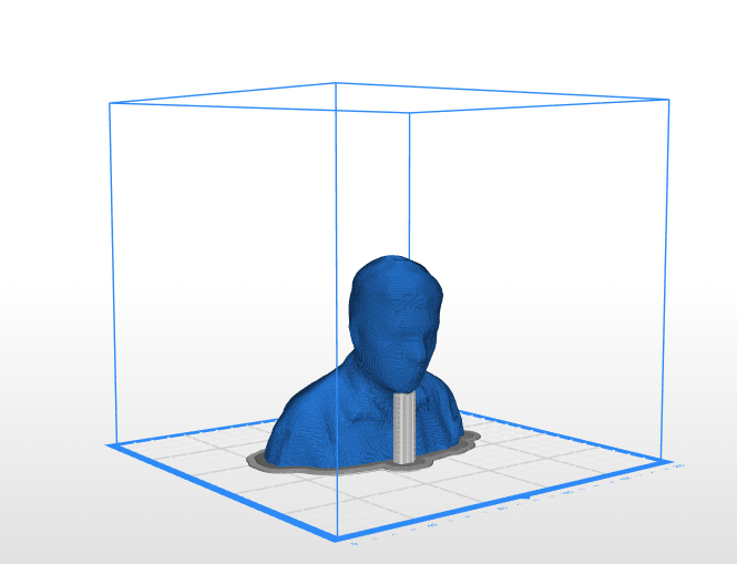 Finally the image is exported, this process generates two files that must be copied to the
memory that is inserted into the 3d printer. You need to check the export the report to a txt
file option.
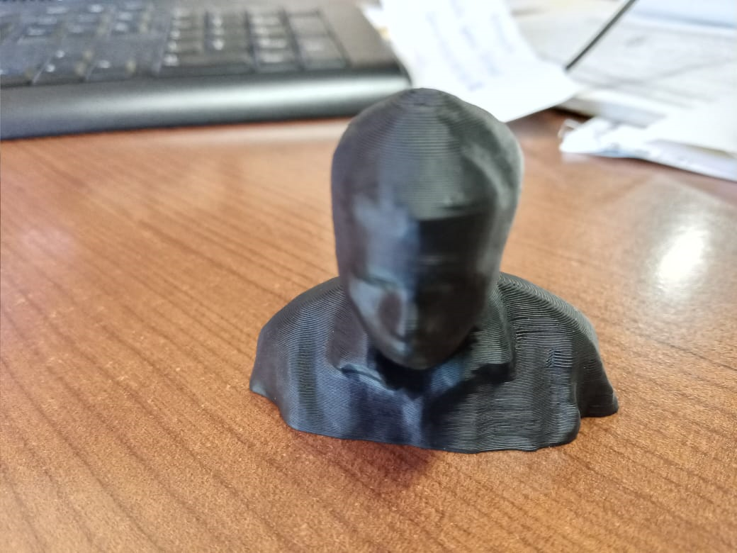 3d model