Introduction.
Once again this week was exciting for me, because I was able to know many things that have to do with the input of devices, that is, this week I was able to know what components can be used to send input data and that based on the needs You can use sensors that, by the way, there is a great variety: to measure temperature, humidity, distance, among others, there are also one-color, two-color or three-color (RGB) LEDs, the communication or port that it is the means by which the information is sent to the electronic board is a fundamental component in the design.
individual assignment
Measure something: add a sensor to a microcontroller board that you have designed and read it.
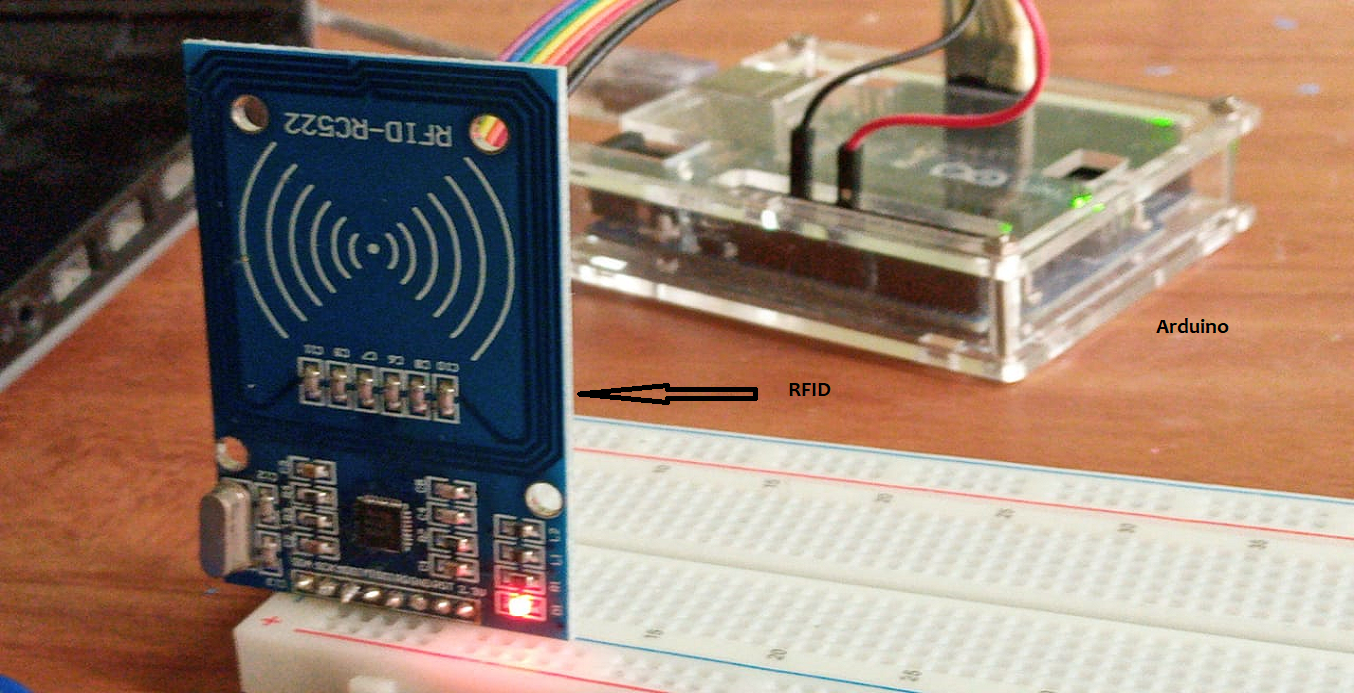
rfid-rc522
Because in my project I am going to integrate RFID radio frequency identification, this week I am starting to learn about this technology, which is why I have decided to do basic tests. The idea is to use a rfid-rc522 module that reads a card and identifies its id and its sectors.NXP Semiconductors has developed the MIFARE MF1S503x to be used in a contactless smart card according to ISO/IEC 14443 Type A. The MIFARE MF1S503x IC is used in applications like public transport ticketing and can also be used for various other applications
Required material
- Arduino uno
- Module rfid
- Card mifare
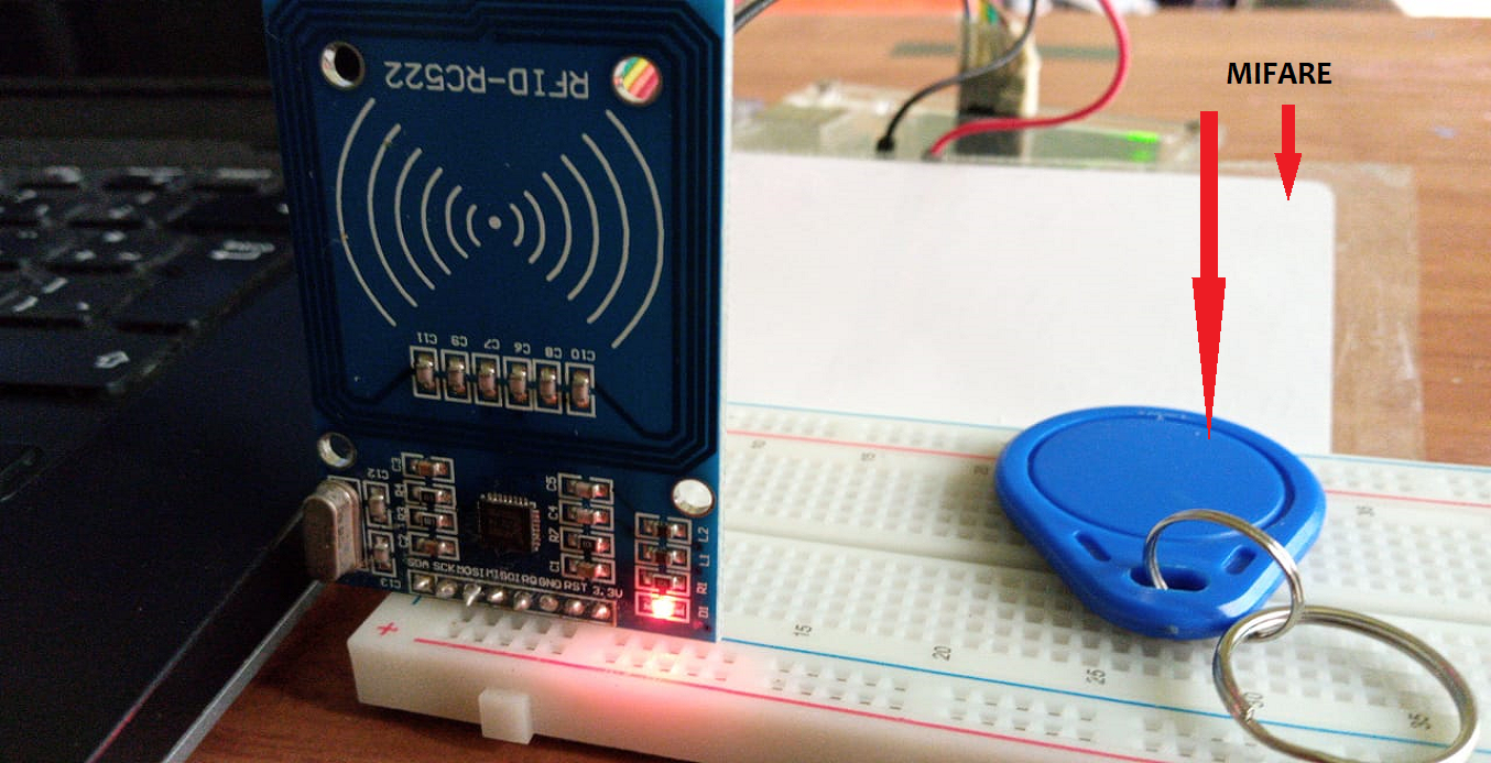
MIFARE
Let's do it. Pin Out for Uno
| RC522 MODULE | Arduino Uno | |
|---|---|---|
| SDA | D10 | |
| SCK | D13 | |
| MOSI | D11 | |
| MISO | D12 | |
| GND | GND/td> | |
| RST | D9 | |
| 3.3V | 3.3V | |
-
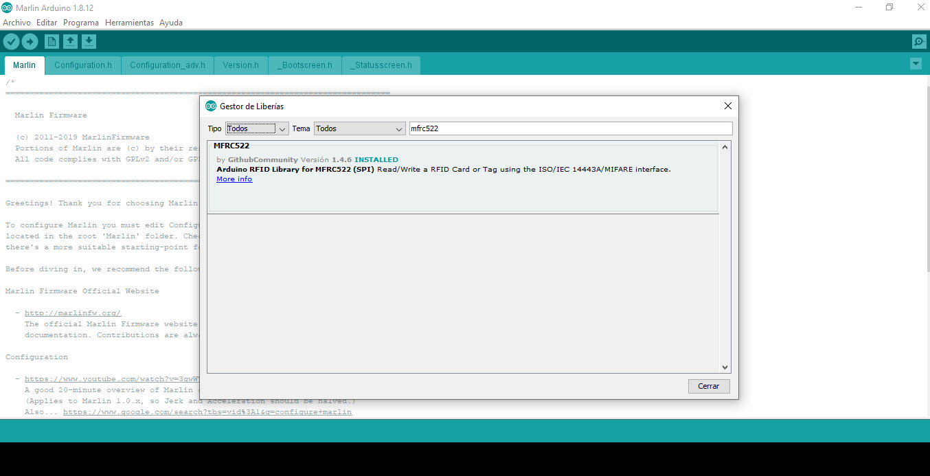
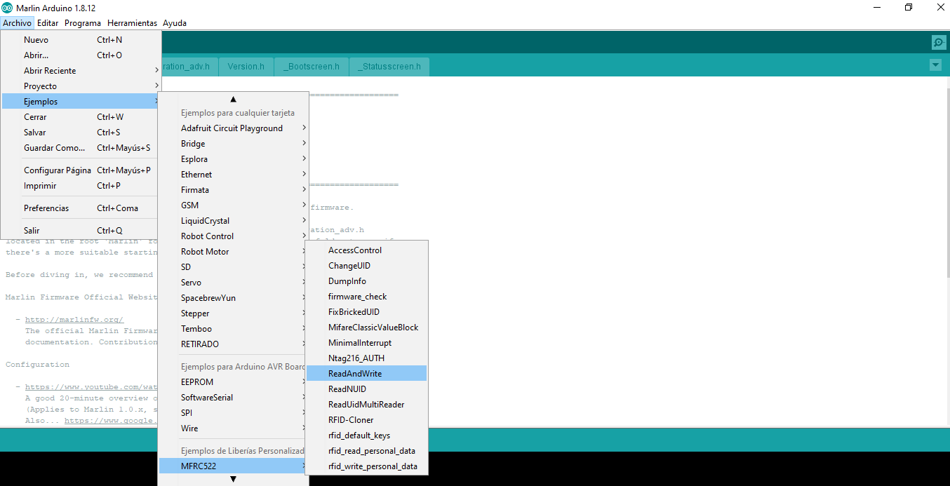
In arduino ide it is necessary to add a library, for this in the tools menu select
manage libraries and search for MFRC522, once located click on install.
-
Now I am going to create a code for writing to the mifare card, it is a simple
example that consists of storing hello world in Spanish, English and French, below
is the code.
#include <
SPI.h>
#include <MFRC522.h>
#define RST_PIN 9
#define SS_PIN 10
MFRC522 mfrc522(SS_PIN, RST_PIN);
MFRC522::MIFARE_Key key;
String texts[3]={
"hola mundo ",
"hello world ",
"salut monde "
};
void setup() {
Serial.begin(9600);
while (!Serial);
SPI.begin();
mfrc522.PCD_Init();
// Prepare the key (used both as key A and as key B)
// using FFFFFFFFFFFF which is the default at chip delivery from the factory
for (byte i = 0; i < 6; i++) {
key.keyByte[i] = 0xFF;
}
}
void loop() {
if ( ! mfrc522.PICC_IsNewCardPresent())
return;
if ( ! mfrc522.PICC_ReadCardSerial())
return;
byte sector = 1;
byte blockAddr = 4;
byte trailerBlock = 7;
MFRC522::StatusCode status;
mfrc522.PCD_Authenticate(MFRC522::PICC_CMD_MF_AUTH_KEY_A, trailerBlock, &key, &(mfrc522.uid));
mfrc522.PCD_Authenticate(MFRC522::PICC_CMD_MF_AUTH_KEY_B, trailerBlock, &key, &(mfrc522.uid));
for (int i = blockAddr; i < trailerBlock; i++) {
status = (MFRC522::StatusCode) mfrc522.MIFARE_Write(i, texts[i-4].c_str(), 16);
if (status != MFRC522::STATUS_OK) {
Serial.print(F("MIFARE_Write() failed: "));
Serial.println(mfrc522.GetStatusCodeName(status));
}
else {
Serial.print("Done "); Serial.println(i);
}
delay(30);
}
// Halt PICC
mfrc522.PICC_HaltA();
// Stop encryption on PCD
mfrc522.PCD_StopCrypto1();
delay(500);
}
-
Verify that the board is arduino uno and that the port is correct, then upload.
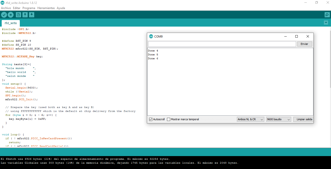 With this, the desired information was already stored on the card.
-
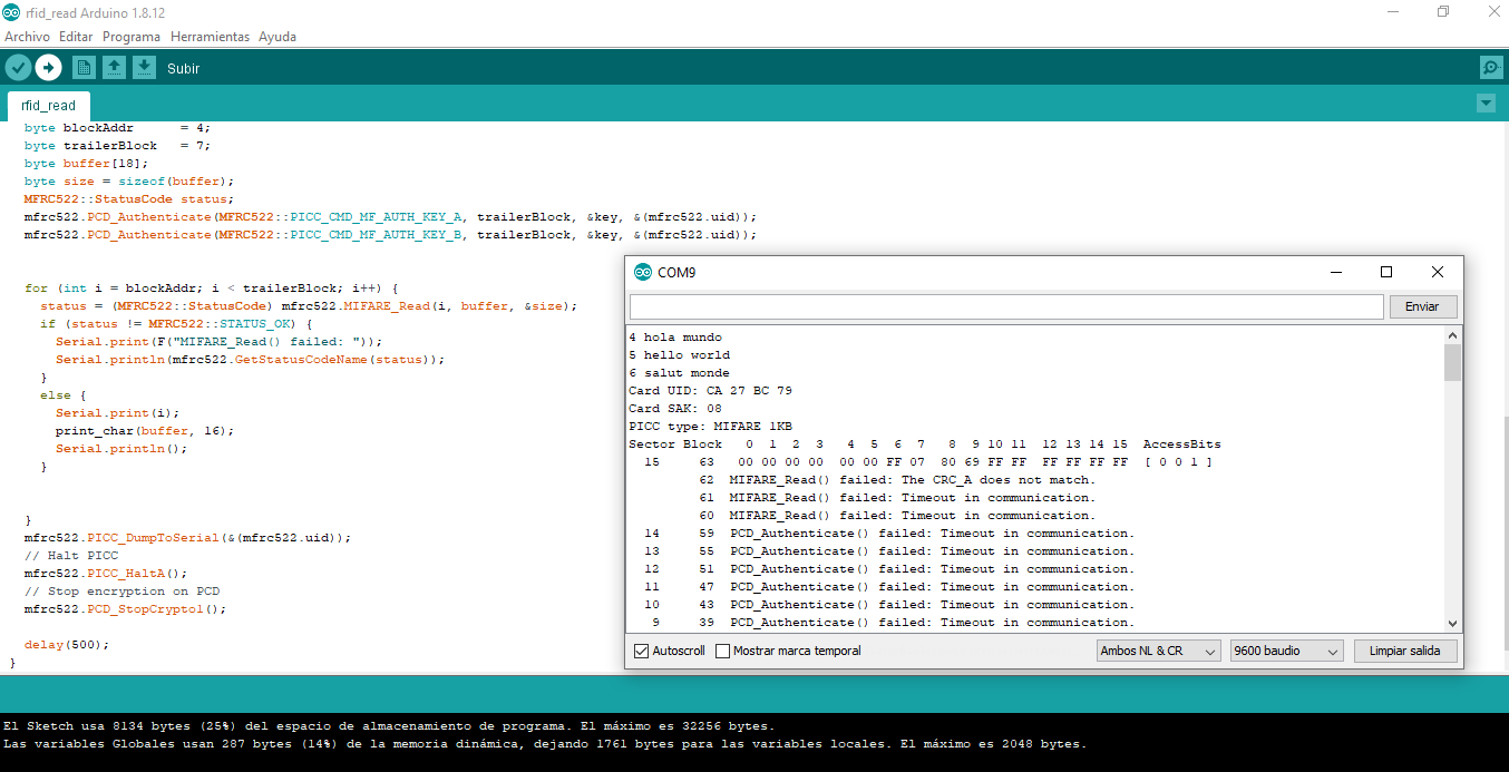
Then it is necessary to create the code that is used to read the information
contained in the card.
#include <
If for some reason you remove the card from the rfid module it sends a communication error: Timeout in communication.SPI.h>
#include <MFRC522.h>
#define RST_PIN 9
#define SS_PIN 10
MFRC522 mfrc522(SS_PIN, RST_PIN);
MFRC522::MIFARE_Key key;
void print_char(byte *buffer, byte bufferSize) {
Serial.print(" ");
for (byte i = 0; i < bufferSize; i++)
Serial.print((char)buffer[i]);
}
void setup() {
Serial.begin(9600);
while (!Serial);
SPI.begin();
mfrc522.PCD_Init();
// Prepare the key (used both as key A and as key B)
// using FFFFFFFFFFFF which is the default at chip delivery from the factory
for (byte i = 0; i < 6; i++) {
key.keyByte[i] = 0xFF;
}
}
void loop() {
if ( ! mfrc522.PICC_IsNewCardPresent())
return;
if ( ! mfrc522.PICC_ReadCardSerial())
return;
byte sector = 1;
byte blockAddr = 4;
byte trailerBlock = 7;
byte buffer[18];
byte size = sizeof(buffer);
MFRC522::StatusCode status;
mfrc522.PCD_Authenticate(MFRC522::PICC_CMD_MF_AUTH_KEY_A, trailerBlock, &key, &(mfrc522.uid));
mfrc522.PCD_Authenticate(MFRC522::PICC_CMD_MF_AUTH_KEY_B, trailerBlock, &key, &(mfrc522.uid));
for (int i = blockAddr; i < trailerBlock; i++) {
status = (MFRC522::StatusCode) mfrc522.MIFARE_Read(i, buffer, &size);
if (status != MFRC522::STATUS_OK) {
Serial.print(F("MIFARE_Read() failed: "));
Serial.println(mfrc522.GetStatusCodeName(status));
}
else {
Serial.print(i);
print_char(buffer, 16);
Serial.println();
}
}
mfrc522.PICC_DumpToSerial(&(mfrc522.uid));
// Halt PICC
mfrc522.PICC_HaltA();
// Stop encryption on PCD
mfrc522.PCD_StopCrypto1();
delay(500);
}
-
I want to clarify that part of the code I presented was taken from the example of
the MFRC522.h library, previously installed.
-
Output
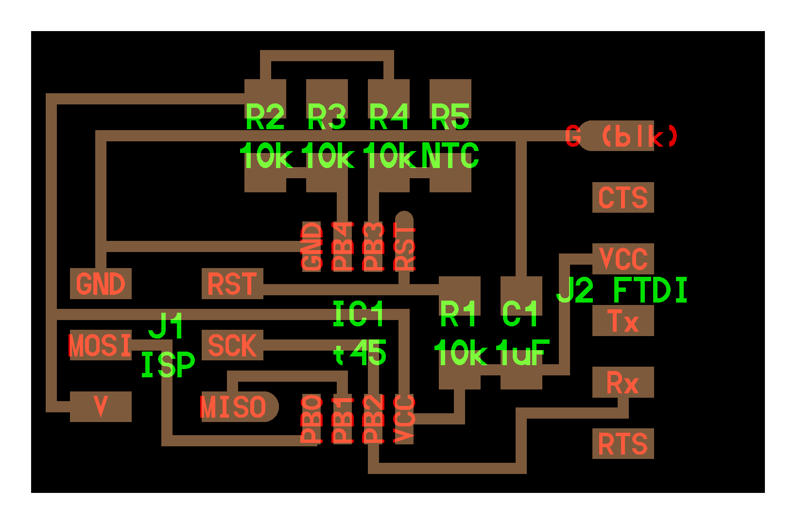
After doing the tests with the material that was available, I chose to make a board to
measure temperature "hello.temp.45"
The first step was to download the

Board
components
Components
| quantity | Name | |
|---|---|---|
| 1 | ISP 2X3 PROGRAMMING HEADER | |
| 1 | Attiny45 Microcontroller | |
| 4 | Resistors 10k | |
| 1 | Capacitor 1 uF | |
| 1 | FDTI 6-Pin Header | |
| 1 | THERMISTOR NTC 10KOHM 3750K | |
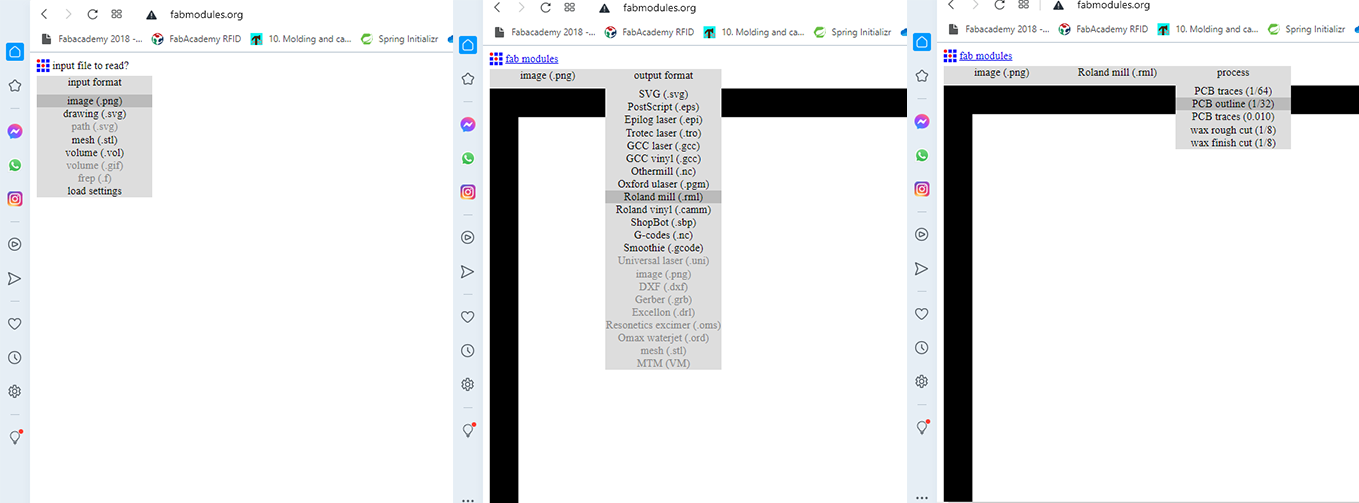
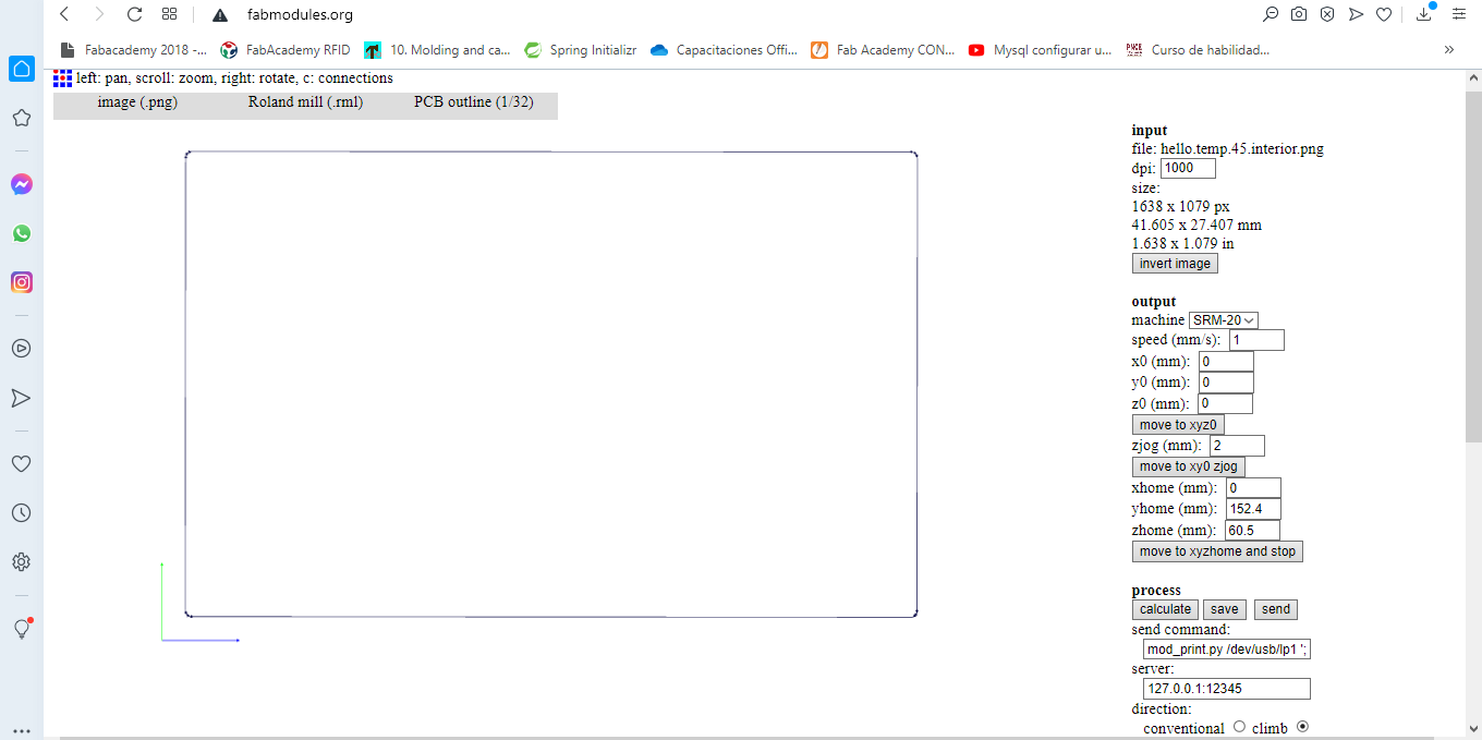
It is time to make use of the fabmodules tool, to make the selection process of the png
image, until the calculation and finally the generation of the file to do the milling.
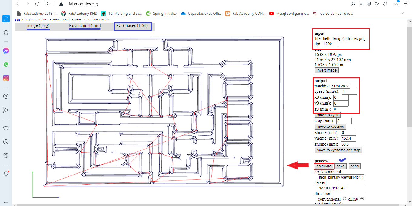
Repeat the procedure to create the internal milling file hello.temp.45.
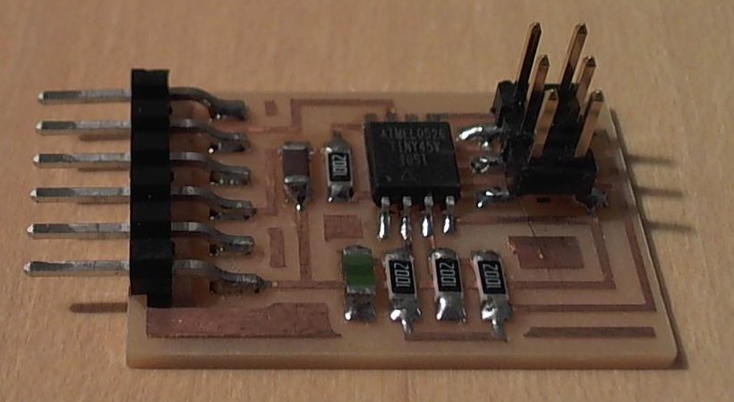
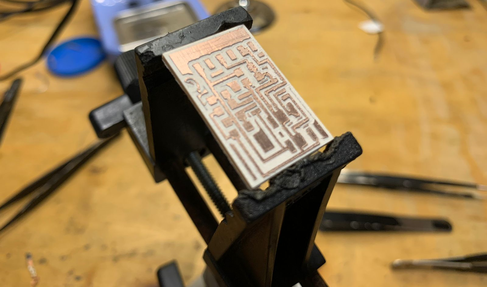
Manufactured board.
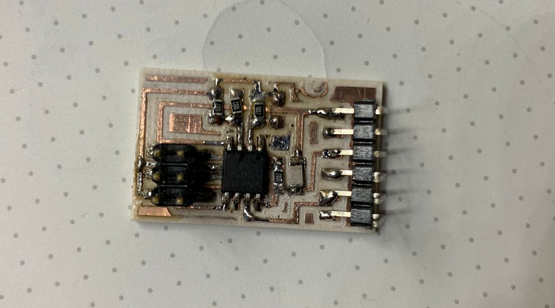
Electronic components ready.
Next download Python and PySerial
Connect the FabISP to the programming header on the Hello Temp board, and connect the FTDI cable to the Hello Temp board.
Download the files below and place them in a folder on your desktop labeled hello.temp
After downloading, open the terminal window and navigate to the hello.temp folder on the desktop by entering the following commands:
cd
cd desktop
cd hello.temp
Next type:
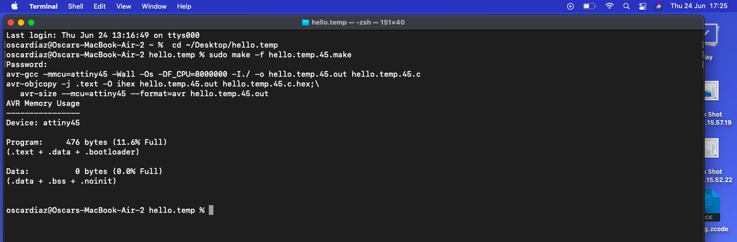
sudo make -f hello.temp.45.make
if you are successful - you will see this response from the system:
Next type:
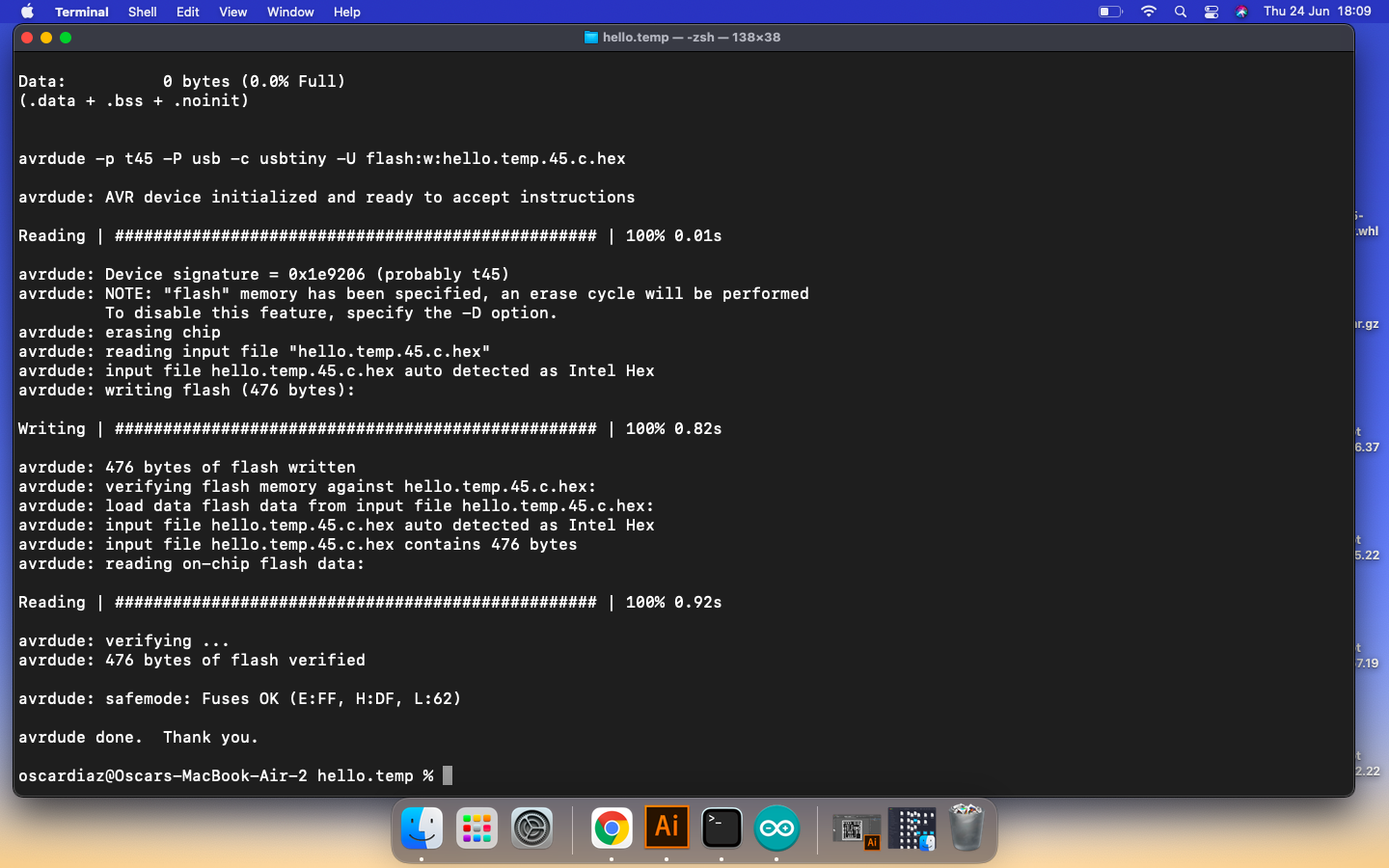
avrdude -p t45 -c usbtiny -U flash:w:hello.temp.45.c.hex
if all goes well, you will see this response from the system::
Next type:
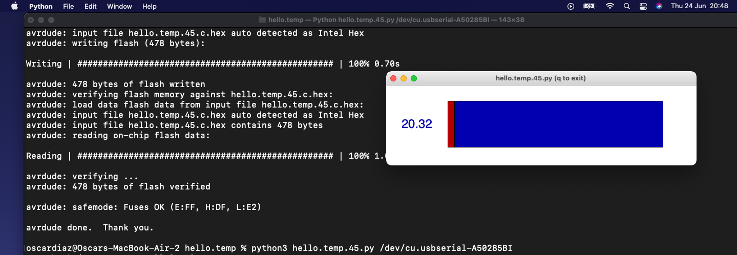
python3 hello.temp.45.py /dev/cu.usbserial-A50285BI
if you are successful - you will see this response from the system:
Group assignment.
Probe an input device's analog levels and digital signals.
-
Following the references of the sensor configuration by Arduino, we proceeded to make the physical connections of the sensor current input to the voltage output of the Arduino microcontroller:
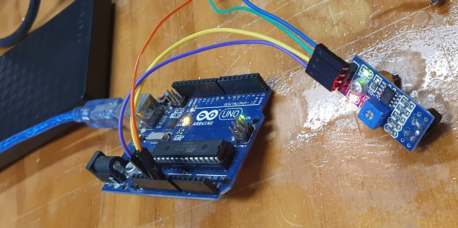
-
Program the Arduino to receive input data, using the following code:
const int sensorPin = 9; void setup () { Serial.begin (9600); // start serial port pinMode (sensorPin, INPUT); // define pin as input } void loop () { int value = 0; value = digitalRead (sensorPin); // digital pin reading if (value == LOW) { Serial.println ("TCRT5000L activated"); //dark zone } delay (1000); } -
Now you have to connect the oscilloscope to the electrical supply and then connect it with the digital and analog sensor output.
-
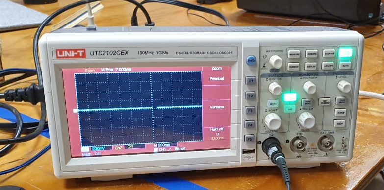
Measure the digital and analog sensor outputs, based on the data displayed by the oscilloscope.
Digital measurement:
In this we can see that there are two states, it detects and does not detect, for the case in which the infrared sensor detects something it sends a logical 0, otherwise it will send a logical 1.
Analog Measure:
In this other case, what is observed is that as time passes and we move the sensor it will detect different values, this being the description of an analog signal, since it will have a value at each moment of time.