-
01. Principles and practices
-
02. Project management
-
03. Computer-Aided design
-
04. Computer controlled cutting
-
05. Electronics production
-
06. 3D Scanning and printing
-
07. Electronics design
-
08. Computer controlled machining
-
09. Embedded programming
-
10. Input devices
-
11. Applications and implications
-
12. Output devices
-
13. Interface and application programming
-
14. Invention, intellectual property and income
-
15. Networking and communications
-
16. Molding and casting
-
17. Wildcard week
-
18. Machine design
-
19. Project development
-
Glossary
Week 5. Electronics production
Feb 25, 2020
Assignment
Group assignment
- Characterize the design rules for your PCB production process
Individual assignment
- Make an in-circuit programmer by milling and stuffing the PCB, test it, then optionally try other PCB processes
Before starting
This week, I had a hard time understanding the words showing up while working on the assignment. So I googled the definition of the terms and wrote them down here. There are some words I still can't fully understand, but it helped me to organize what I knew and what I didn't know.
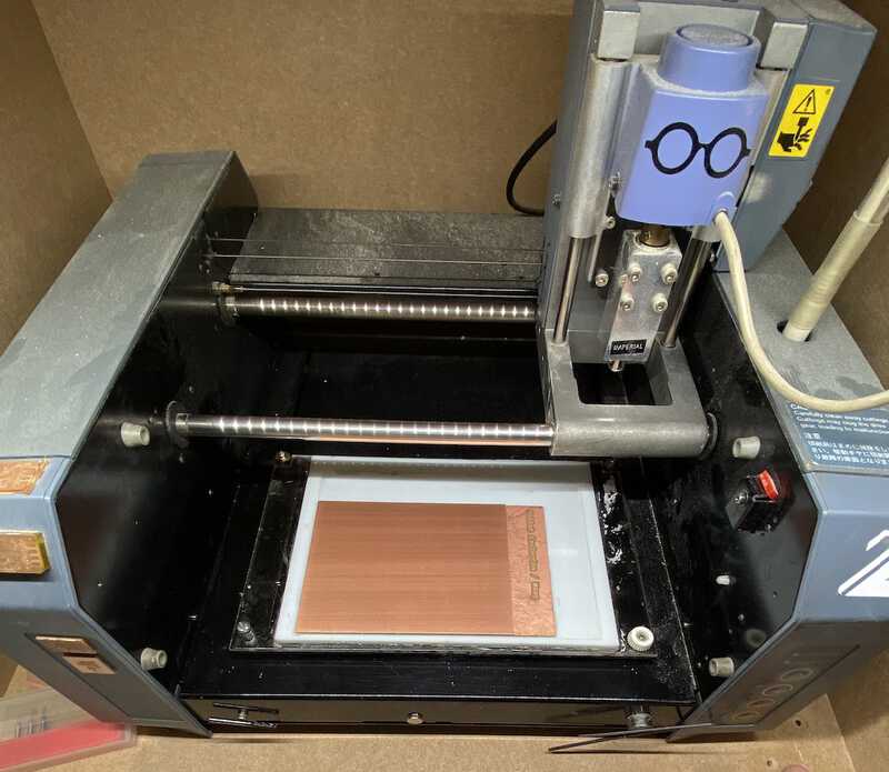
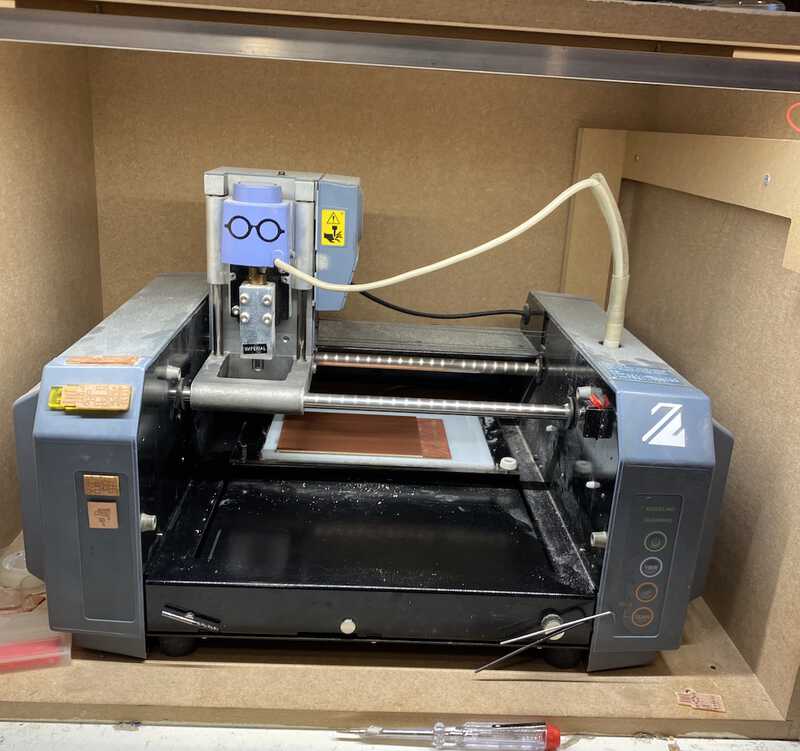
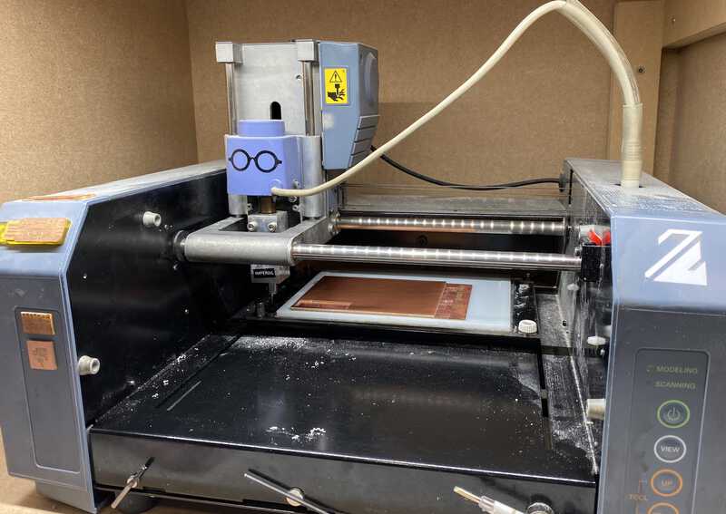
How to use a small milling machine
The small milling machine we have at Waag is a Roland Modela MDX-20. This week, Henk taught us how to use the machine step-by-step.
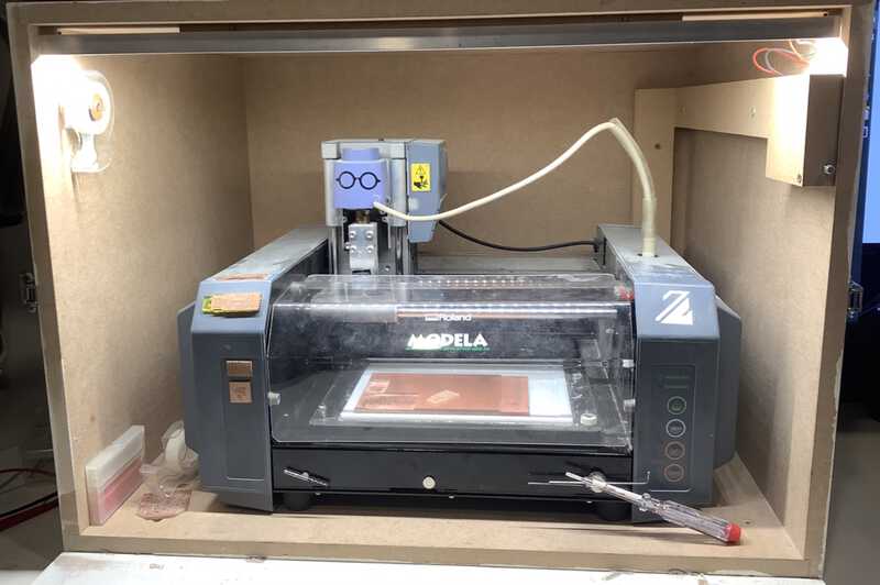
There are two types of copper board, FR1 (FR = Flame Retardant)and FR4. We are using FR1. FR1 is safer because it's laminated with paper, while FR4 is laminated with glass fiber which can be harmful to our lungs.
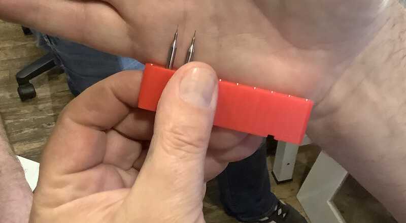
The endmills we had were 0.4mm and 0.8mm, and we used the 0.4mm one for the tracing and 0.8mm for the outline.
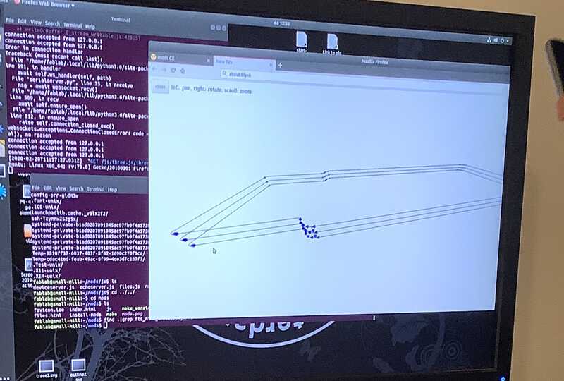
We used the community version of the mods which was made by one of the Fab Academy instructors.
For milling traces
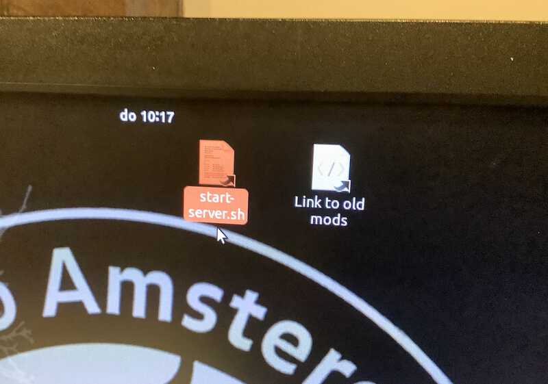
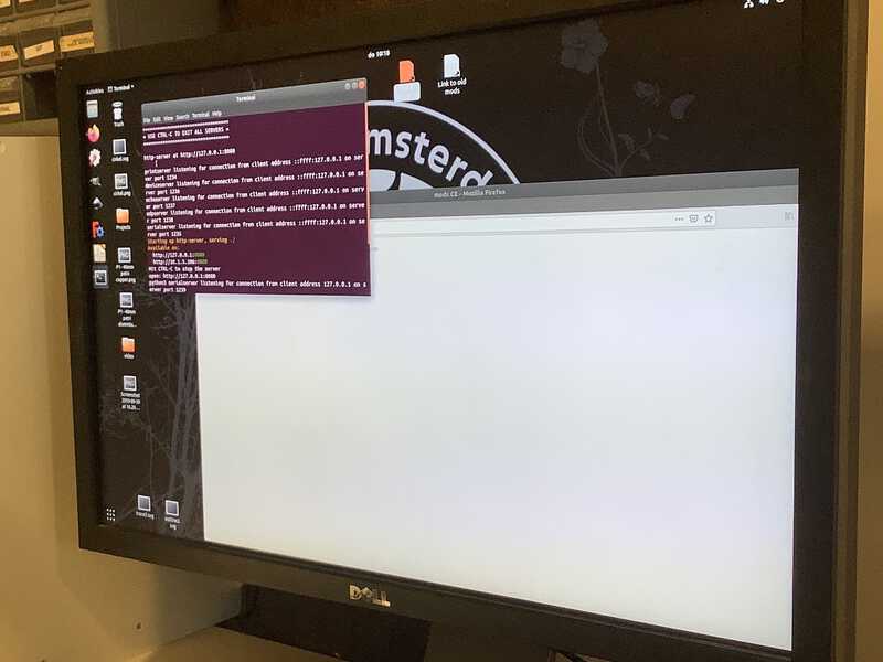
Click start-server.sh on the computer
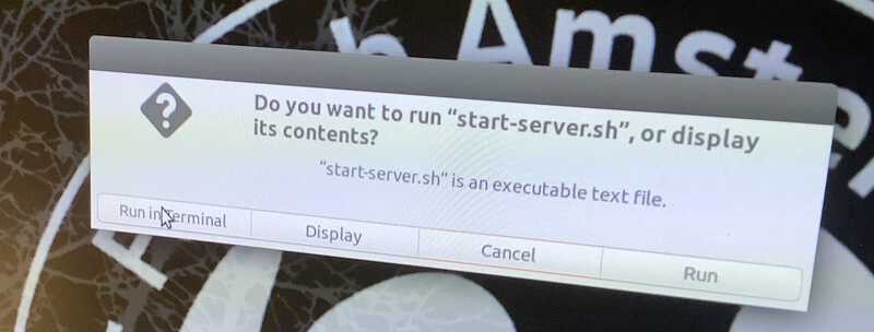
When the popup shows up, click run in terminal. It will open Firefox browser and a terminal
You can type
dmeg | grep USB0to see if the machine is connectedTurn the milling machine on
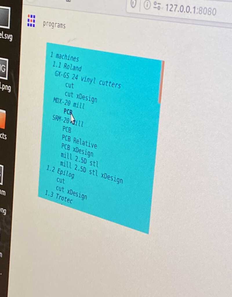
On the mods screen, click Menu > Program > Open Program.
Then, you will see the list of machines. Click the PCB button underneath the MDX 20 mill text
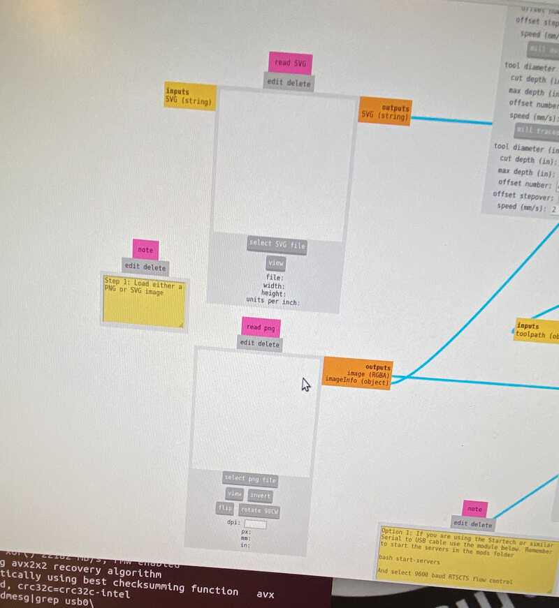
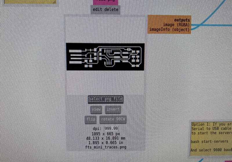
You can select either a PNG or a SVG file. Import a tracing file
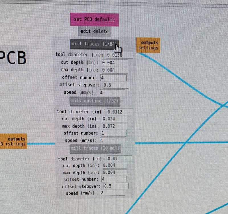
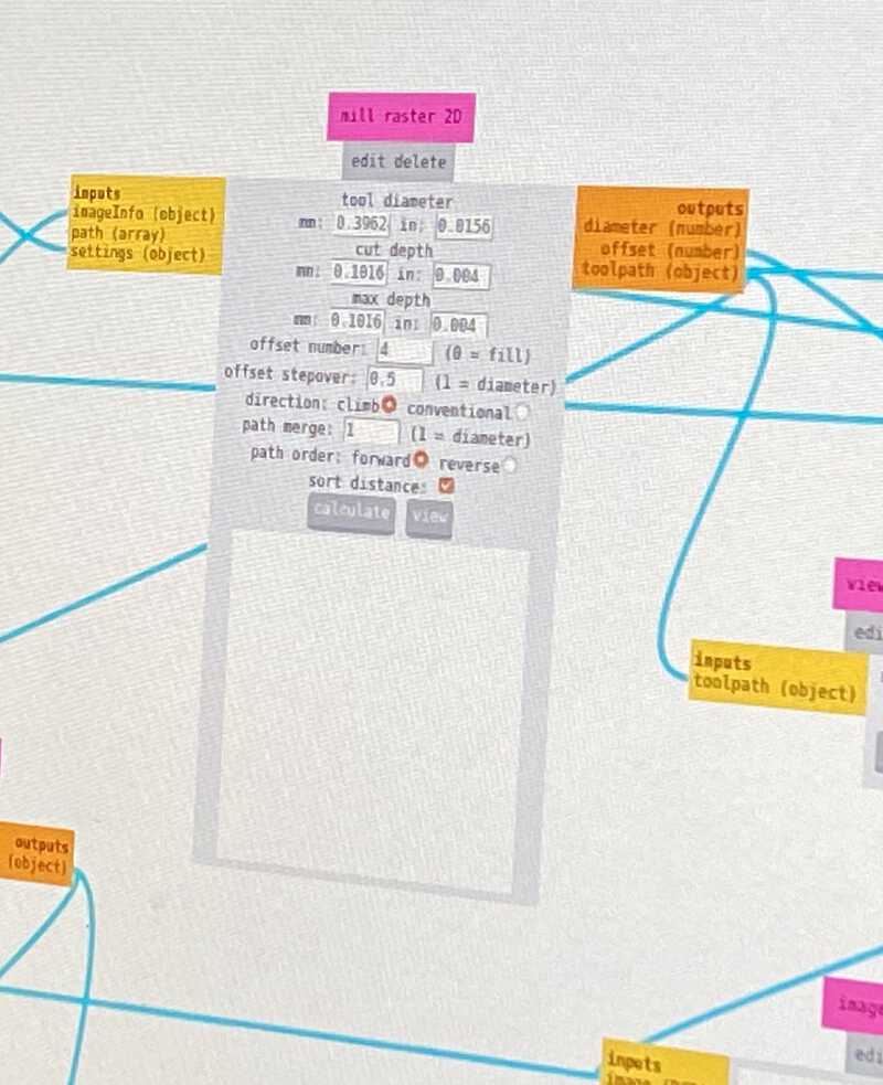
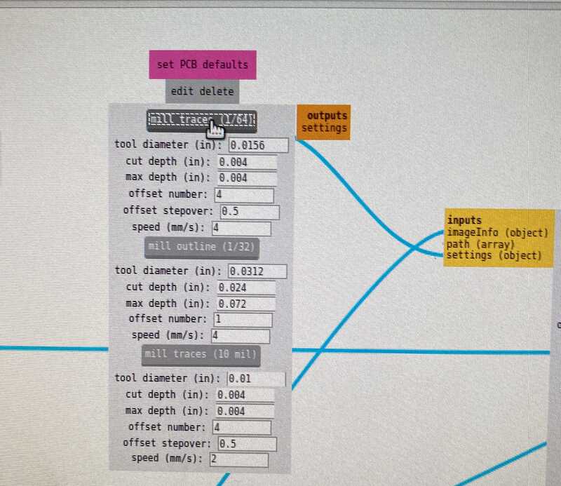
In the set PCB defaults module, select mill traces
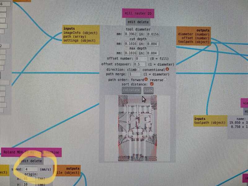
Then, in the mill raster 2D module, you will see that the tool diameter is set to 0.3962. In that module, set:
offset number to 4
offset stepover to 0.5
direction to climb
path merge to 1
path order to forward
check sort distance
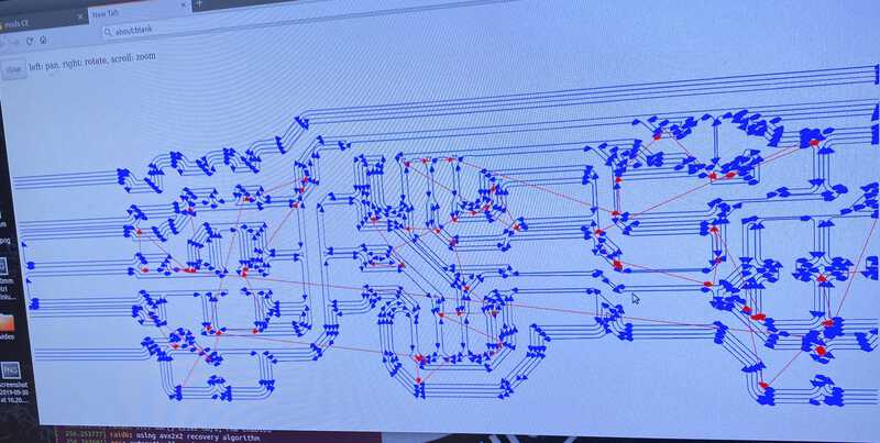
Then, click the calculate button and the view button
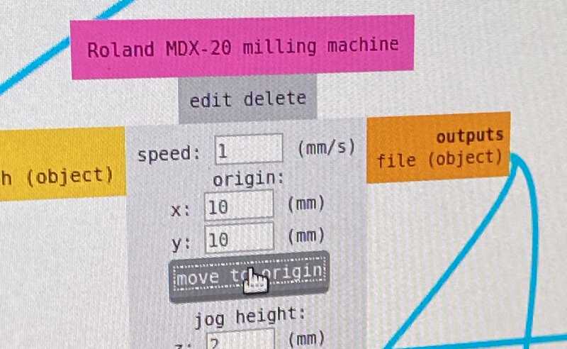
Go to the Roland MDX-20 milling machine module and change the speed to 1m/s
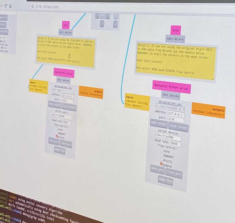
We tried to use the Websocket serial module, but it didn't work for some reason. Instead, we used the WebSocket Python serial module and set the flow control to RTSCTS. We left the other settings as default
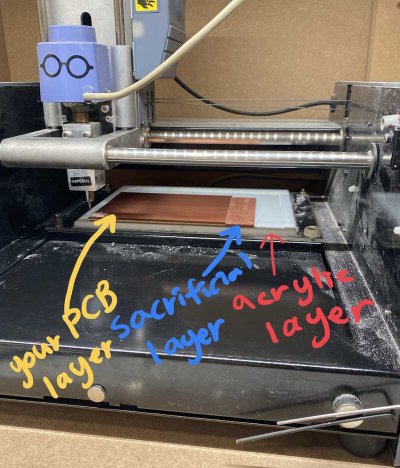
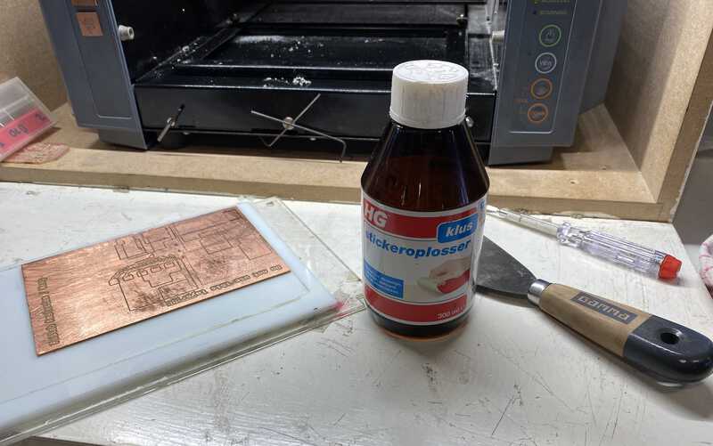
If you want to detach the used copper board from the sacrificial plate, you can use a scrapper. After detaching the copper board, there still might be some sticky things on the plate. Use a sticker dissolver to remove the residue.
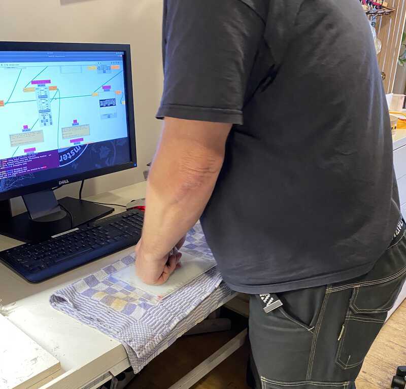
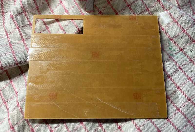
Put a double sided tape on the copper board you will use. The tape should cover the entire board.
Put a towel under the copper board and press it from the top so that it sticks well
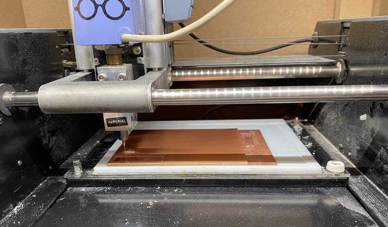
Turn on the machine and press the View button so that the milling head and the plate move to the front
Place the copper board on the milling machine plate and screw the copper board on to the plate
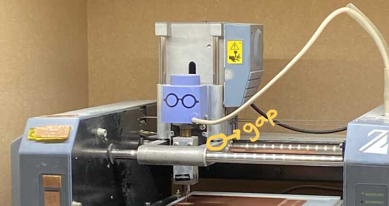
Put the endmill all the way into the nozzle hole
Press the View button on the machine. The plate will move to the back of the machine
Press the Down button so that the endmill moves all the way down. When the endmill is all the way down, press the Up button to lift it a little bit
On the Roland MDX-20 milling machine module, click move to origin
If the origin doesn't look right, change the x and y value until they are set to the location you want
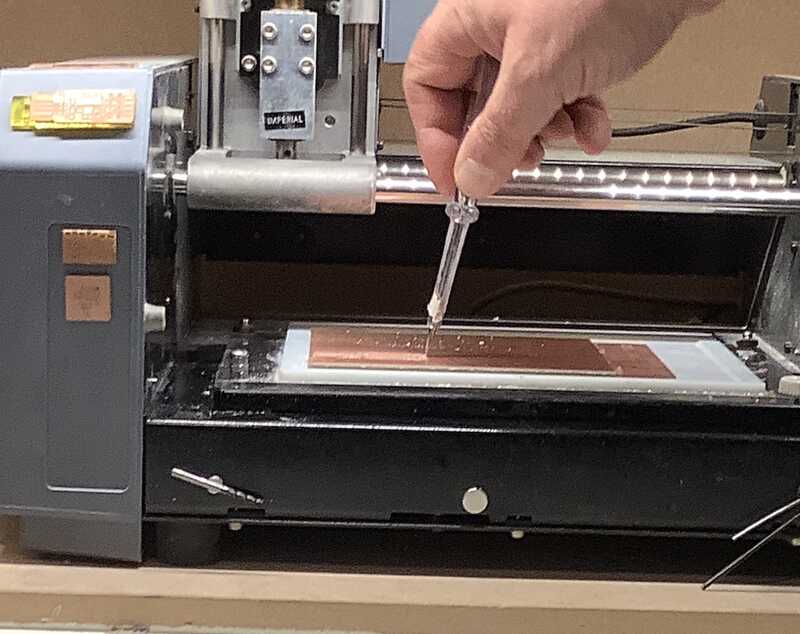
When the origin is located in the right position, lower the endmill so that it touches the copper board.
Rotate the endmill a bit to clean the dust on the surface
When everything is ready, click send file
If there's something wrong with the milling process, press the View button on the machine to stop it. Then, click the cancel button on the software. And hold the up and down button on the machine together until the blinking light goes away.
We used the 0.4mm, 2-flutes endmill.
Write down the origin value (x,y) just in case you need it later
For milling an outline
Import an outline file
Replace the 0.4mm endmill to 0.8mm one
On the set PCB defaults module, select mill outline
On the mill raster 2D module, set the offset to 1
On the Roland MDX-20 milling machine module, set the speed to 4m/s
Click View to see if it looks good. As you can see below, the outline should have 3 layers of cut
Click move to origin to see if the endmill is in the proper location
Move the nozzle a bit higher than when you are milling traces. It's because the endmill will go down deeper when it carves outlines. So if the nozzle is located all the way down, there's no space for the nozzle to go down when it has to cut a deeper layer.
When every step is done, click send file
After the milling is done
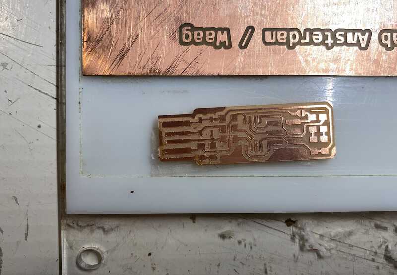
Jiggle the PCB on the copper board with a sharp knife and take it out of the board
Scrape out the part shown in the photo below to prevent a short circuit
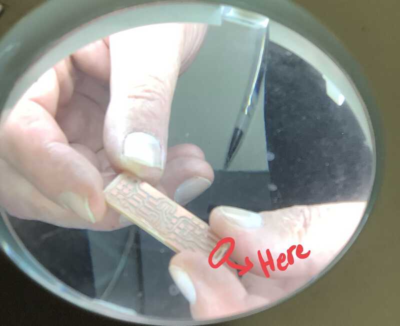
Once the process is done, you can start soldering. Happy soldering!
Group assignment
Group assignment documentation
This week's group assignment was to characterize our small milling machine. We milled this line test file with 4 different settings (1 flute endmill, 2-flutes endmill, the climb direction and conventional direction).
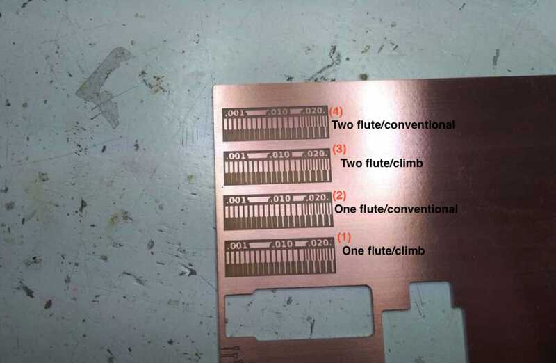
From our results it looked like both one flute and climb produced smoother lines in more detail. In order of producing results that most resembled the .png, we ranked the milling:
One flute/climb
One flute/conventional
Two flute/climb
Two flute/conventional
What went wrong
On our first trial, the endmill didn't scrape the copper board. We stopped the machine by pressing the view button and clicked the cancel button on the computer. But when we pressed the view button again to adjust the height of the endmill, the machine restarted the previous work. We tried to reset the machine, but it kept rerunning the previous milling. We tried to press the up and down bottons together until the blinking light went away, but it didn't go away.
We finally asked Henk, and he told us to do what we just did. It turned out it takes pretty long for the blinking light to go away, and we didn't wait long enough. Also, You have to cancel the job in the mods and close the port and socket. Otherwise, it will continue the previous job even if you reset the machine. Finally, we were able to reset the machine and restart the job.
Individual assignment
1) AVR ISP
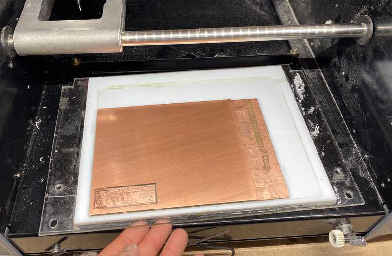
We used Brian's board to make the ISP. I exactly followed the steps I wrote above when I used the small milling machine.
1. Remove the sticky residue from the sacrificial copper board
2. Put a double sided tape on the back side of a copper board
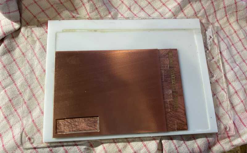
3. Place the copper board on the sacrificial board
4. Flip it over and press it from the top so that it sticks well. Don't forget to put the tower underneath it to prevent damaging the copper board
5. Slide the copper board into the milling machine
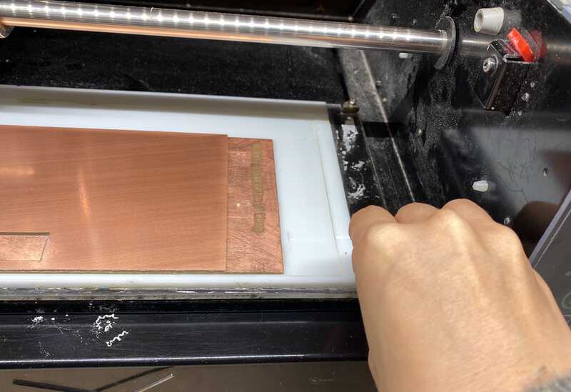
6. Screw the board onto the milling machine
7. Import the tracing file
8. Click the mill trace button
9. Press the View button on the machine and click the send file on the mods
10. The milling process will start
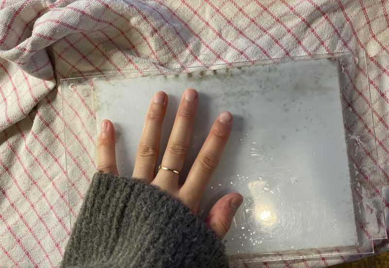
After the milling was done, I washed it with hand soap and dried it. The lines on my PCB board looked more scratchy than my classmates ', and it was because I accidentally used the old endmill. I will use the new endmill next time.
After washing the board, I soldered it as these instructions said.
I've done soldering before so it wasn't that hard. But I later found that there were some parts that weren't soldered properly, so I had to do it again. I think I need more practice on soldering.
The milling part was done without that much trouble. But after soldering, when Henk checked my circuit, the red LED light which was supposed to be turned on wasn't. It turned out that the one of the resistors wasn't fully soldered on the board. After re-soldering it, the red LED was turned on.
But I had another problem. I downloaded CrossPack and the firmware as the instructions said. Then, I connected my board with Henk's ISP and ran the make command. This command was supposed to create a file called the hex file, but I got this error message instead.
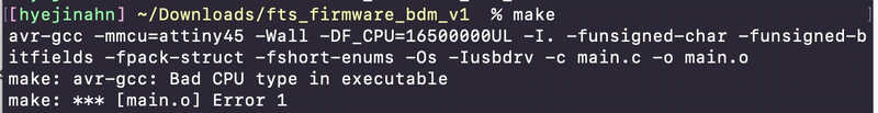
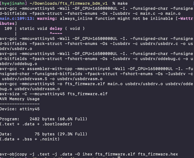
So I searched for the error message on the Fab Academy archive and found this link. This student had the same error message and he installed avr-gcc to fix the error. So I downloaded avr-gcc using homebrew. Then I ran the make command again, and it created the hex file successfully.
Then, I ran brew install avrdude. Then, I ran make flash to program its flash memory with the contents of the .hex file. Then, I got this error.
avrdude: initialization failed, rc=-1
All of us got the same error message. Henk told us to run avrdude -c usbtiny -p t45 on the terminal. After running that command, I ran the rest of the commands. These are the commands I ran.
avrdude -c usbtiny -p t45 # to specify programmer type and AVR device
make flash # uses the programmer to load it onto the target chip
make fuses # programs the fuse bits on the target chip
make rstdisbl # blows the reset fuse
And this was the output on the terminal.
[hyejinahn] ~/Downloads/fts_firmware_bdm_v1  % avrdude -c usbtiny -p t45

avrdude: AVR device initialized and ready to accept instructions

Reading | ################################################## | 100% 0.01s

avrdude: Device signature = 0x1e9206 (probably t45)

avrdude: safemode: Fuses OK (E:FF, H:DF, L:62)

avrdude done.  Thank you.

[hyejinahn] ~/Downloads/fts_firmware_bdm_v1  % make flash
avrdude -p attiny45 -c usbtiny -P usb -e \
	-U flash:w:fts_firmware.hex

avrdude: AVR device initialized and ready to accept instructions

Reading | ################################################## | 100% 0.00s

avrdude: Device signature = 0x1e9206 (probably t45)
avrdude: erasing chip
avrdude: reading input file "fts_firmware.hex"
avrdude: input file fts_firmware.hex auto detected as Intel Hex
avrdude: writing flash (2482 bytes):

Writing | ################################################## | 100% 2.56s

avrdude: 2482 bytes of flash written
avrdude: verifying flash memory against fts_firmware.hex:
avrdude: load data flash data from input file fts_firmware.hex:
avrdude: input file fts_firmware.hex auto detected as Intel Hex
avrdude: input file fts_firmware.hex contains 2482 bytes
avrdude: reading on-chip flash data:

Reading | ################################################## | 100% 4.19s

avrdude: verifying ...
avrdude: 2482 bytes of flash verified

avrdude: safemode: Fuses OK (E:FF, H:DF, L:62)

avrdude done.  Thank you.

[hyejinahn] ~/Downloads/fts_firmware_bdm_v1  % make fuses
avrdude -p attiny45 -c usbtiny -P usb \
	-U lfuse:w:0xE1:m -U hfuse:w:0xDD:m \
	-U efuse:w:0xFF:m

avrdude: AVR device initialized and ready to accept instructions

Reading | ################################################## | 100% 0.00s

avrdude: Device signature = 0x1e9206 (probably t45)
avrdude: reading input file "0xE1"
avrdude: writing lfuse (1 bytes):

Writing | ################################################## | 100% 0.01s

avrdude: 1 bytes of lfuse written
avrdude: verifying lfuse memory against 0xE1:
avrdude: load data lfuse data from input file 0xE1:
avrdude: input file 0xE1 contains 1 bytes
avrdude: reading on-chip lfuse data:

Reading | ################################################## | 100% 0.00s

avrdude: verifying ...
avrdude: 1 bytes of lfuse verified
avrdude: reading input file "0xDD"
avrdude: writing hfuse (1 bytes):

Writing | ################################################## | 100% 0.01s

avrdude: 1 bytes of hfuse written
avrdude: verifying hfuse memory against 0xDD:
avrdude: load data hfuse data from input file 0xDD:
avrdude: input file 0xDD contains 1 bytes
avrdude: reading on-chip hfuse data:

Reading | ################################################## | 100% 0.00s

avrdude: verifying ...
avrdude: 1 bytes of hfuse verified
avrdude: reading input file "0xFF"
avrdude: writing efuse (1 bytes):

Writing | ################################################## | 100% 0.00s

avrdude: 1 bytes of efuse written
avrdude: verifying efuse memory against 0xFF:
avrdude: load data efuse data from input file 0xFF:
avrdude: input file 0xFF contains 1 bytes
avrdude: reading on-chip efuse data:

Reading | ################################################## | 100% 0.00s

avrdude: verifying ...
avrdude: 1 bytes of efuse verified

avrdude: safemode: Fuses OK (E:FF, H:DD, L:E1)

avrdude done.  Thank you.

[hyejinahn] ~/Downloads/fts_firmware_bdm_v1  % make rstdisbl
avrdude -p attiny45 -c usbtiny -P usb \
	-U lfuse:w:0xE1:m -U hfuse:w:0x5D:m \
	-U efuse:w:0xFF:m

avrdude: AVR device initialized and ready to accept instructions

Reading | ################################################## | 100% 0.00s

avrdude: Device signature = 0x1e9206 (probably t45)
avrdude: reading input file "0xE1"
avrdude: writing lfuse (1 bytes):

Writing | ################################################## | 100% 0.00s

avrdude: 1 bytes of lfuse written
avrdude: verifying lfuse memory against 0xE1:
avrdude: load data lfuse data from input file 0xE1:
avrdude: input file 0xE1 contains 1 bytes
avrdude: reading on-chip lfuse data:

Reading | ################################################## | 100% 0.00s

avrdude: verifying ...
avrdude: 1 bytes of lfuse verified
avrdude: reading input file "0x5D"
avrdude: writing hfuse (1 bytes):

Writing | ################################################## | 100% 0.01s

avrdude: 1 bytes of hfuse written
avrdude: verifying hfuse memory against 0x5D:
avrdude: load data hfuse data from input file 0x5D:
avrdude: input file 0x5D contains 1 bytes
avrdude: reading on-chip hfuse data:

Reading | ################################################## | 100% 0.00s

avrdude: verifying ...
avrdude: 1 bytes of hfuse verified
avrdude: reading input file "0xFF"
avrdude: writing efuse (1 bytes):

Writing | ################################################## | 100% 0.00s

avrdude: 1 bytes of efuse written
avrdude: verifying efuse memory against 0xFF:
avrdude: load data efuse data from input file 0xFF:
avrdude: input file 0xFF contains 1 bytes
avrdude: reading on-chip efuse data:

Reading | ################################################## | 100% 0.00s

avrdude: verifying ...
avrdude: 1 bytes of efuse verified

avrdude: safemode: Fuses OK (E:FF, H:5D, L:E1)

avrdude done.  Thank you.
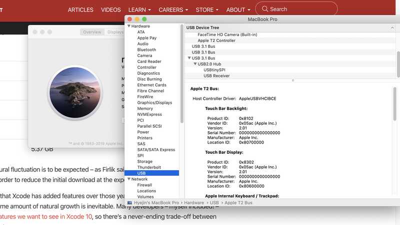
It worked! But when I connected my board to my computer, my computer couldn't find any USBtinySPI. I was frustrated. I checked the board with a multimeter but couldn't find the problem. Eventually, I added more solder on my board just in case there were any disconnections.
After re-soldering it, I tested again and it finally worked!
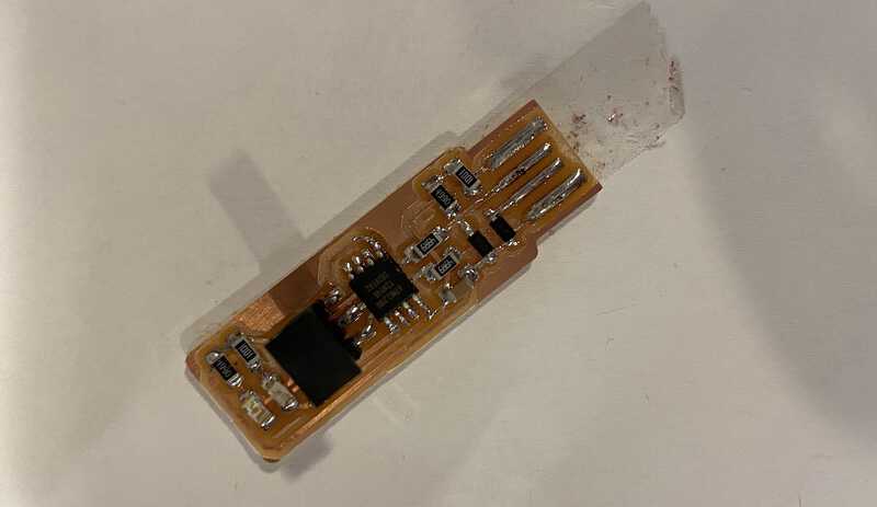
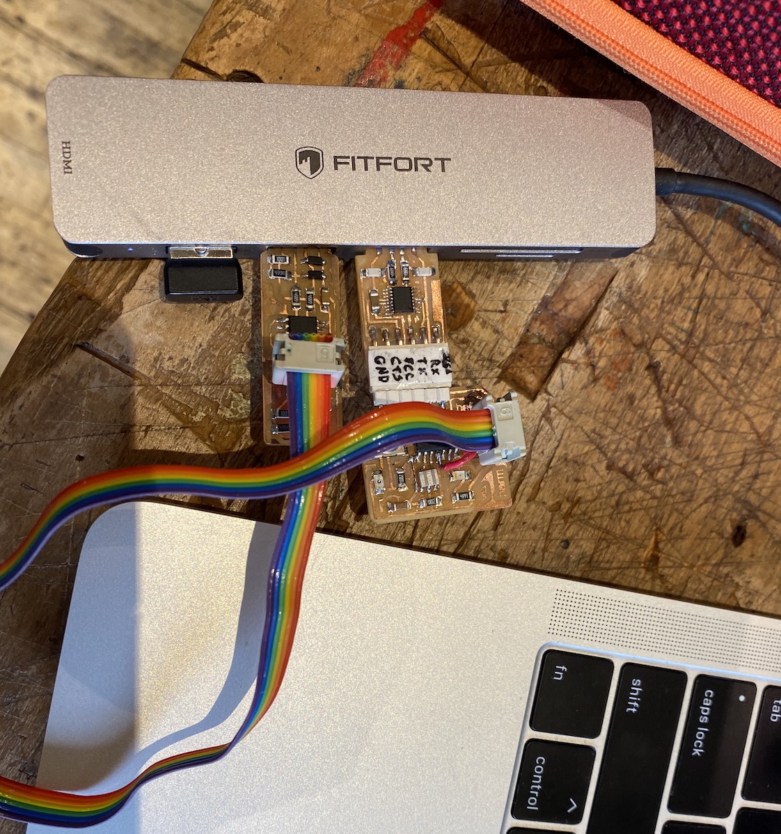
2) FTDI cable
After making the AVR ISP, I milled an FTDI cable. But I burned the board while I was soldering it, so I had to make it again. The circuit lines were much more narrow than the ISP, so I really had to be careful not to mess it up.
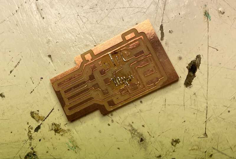
My first trial
On the second trial, I forgot to change the speed to 1 m/s when I milled the trace. I didn't know until the middle of the process. I just thought the milling machine was going faster than yesterday. Later, I realized that the speed was wrong, but I didn't stop it since it was almost done anyway.
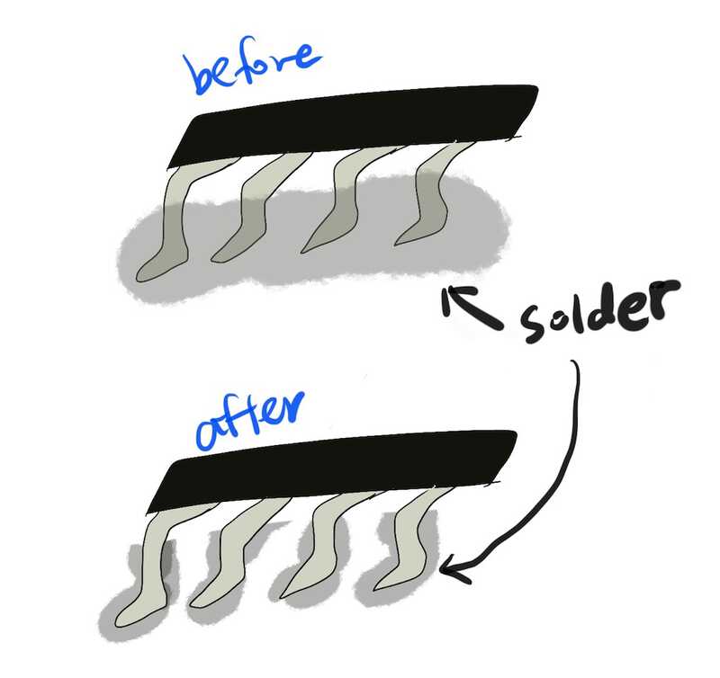
The result was pretty good so I didn't mill it again. The hardest part was soldering the FTDI chip onto the board. The FTDI chip has 16 thin legs and I had to use a trick Henk told us.
First, solder the right top leg onto the board. Then, solder the left bottom leg onto the board. Check if the chip is not moving around, and put the solder all over the legs. After the legs are covered with the solder, suck up the solder lump with a desoldering iron so that the only necessary amount of solder is left.
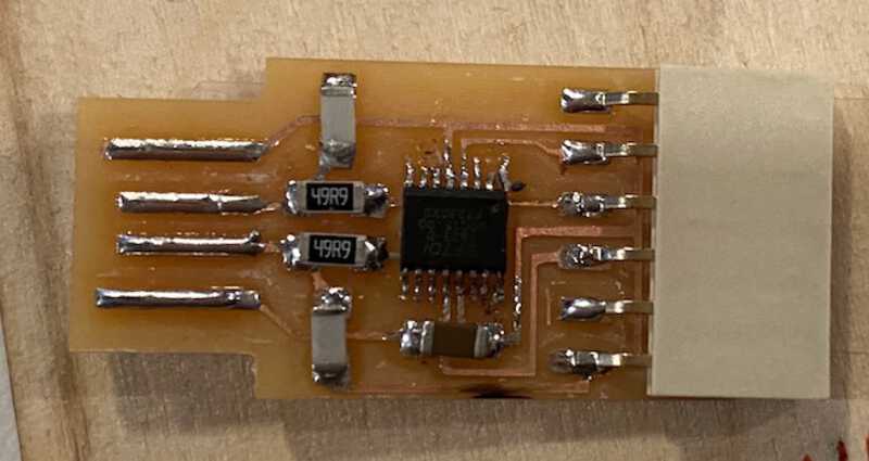
This is the final result of my FTDI cable.
What went wrong
As I mentioned above, I burned the first FTDI board with the desoldering iron. I've never used a desoldering iron before, so I didn't know how long I should leave the iron on the solder lump. Henk said I would see that the solder flows when it's melted, but it was hard to see it because the chip was so tiny. Even on the second try, I had a hard time soldering the FTDI chip but I made it work eventually.
Updated - Removing blob
We (Harm and I) removed the blob and programmed the board as the Brian's documentation said. We uploaded very simple code just to test if it would work, and it worked like a charm.