-
01. Principles and practices
-
02. Project management
-
03. Computer-Aided design
-
04. Computer controlled cutting
-
05. Electronics production
-
06. 3D Scanning and printing
-
07. Electronics design
-
08. Computer controlled machining
-
09. Embedded programming
-
10. Input devices
-
11. Applications and implications
-
12. Output devices
-
13. Interface and application programming
-
14. Invention, intellectual property and income
-
15. Networking and communications
-
16. Molding and casting
-
17. Wildcard week
-
18. Machine design
-
19. Project development
-
Glossary
Week 13. Interface and application programming
April 29, 2020
Assignment
Group assignment
- Compare as many tool options as possible
Individual assignment
- Write an application that interfaces a user with an input or output device that you made
Individual assignment
MQTT & Node-RED
This week's individual assignment is to write an application that interfaces a user with input/output devices I made. For the last several weeks, I’ve been playing around with ESP32-CAM, an RGB LED and a TFT LED display. I set this week’s goal to control them by using the MQTT protocol combined with Node-RED.
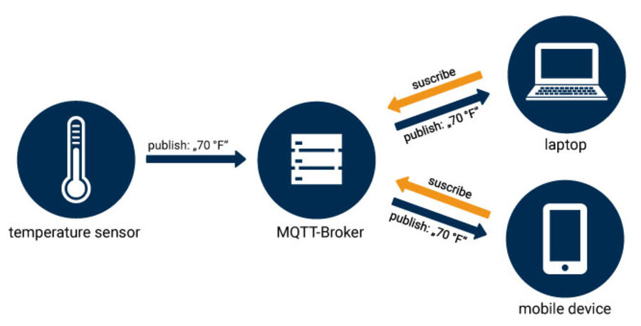
MQTT is a machine-to-machine (M2M)/"Internet of Things" connectivity protocol. It was designed as an extremely lightweight publish/subscribe messaging transport. It is useful for connections with remote locations where a small code footprint is required and/or network bandwidth is at a premium. For example, it has been used in sensors communicating to a broker via satellite link, over occasional dial-up connections with healthcare providers, and in a range of home automation and small device scenarios. It is also ideal for mobile applications because of its small size, low power usage, minimised data packets, and efficient distribution of information to one or many receivers.
- MQTT.org
At first, I was going to use BLE (Bluetooth Low Energy) to communicate between devices. But one of my fellow students, Harm, told me about MQTT saying this might be useful for my project. After doing some research, I decided to apply MQTT instead of BLE. The idea is to use a Raspberry Pi for an MQTT broker, and use Node-RED to program and control it.
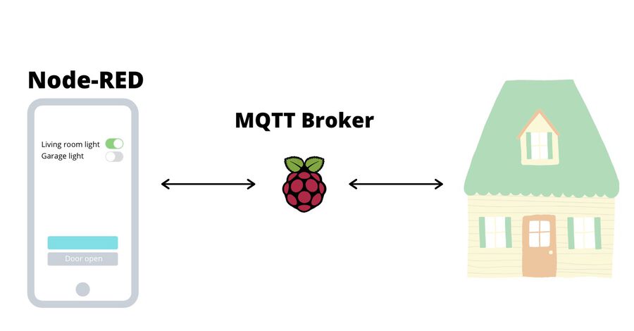
A MQTT broker is a server that receives all messages from the clients and then routes the messages to the appropriate destination clients. Depending on the implementation, a broker can manage up to thousands of simultaneously connected MQTT clients. The broker is responsible for receiving all messages, filtering the messages, determining who subscribed to each message and sending the message to those subscribed clients. The easy way to explain is that it's like the post office. When you send a letter, you don't directly send it to your friend's house. First it goes to the post office and then from there, it is delivered to your friend's house. There are many different ways to run a MQTT broker. In my case, I installed Mosquitto Broker on my Raspberry Pi.
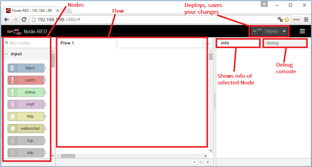
Node-RED is a powerful open source tool for building Internet of Things (IoT) applications with the goal of simplifying the programming component. It uses visual programming that allows you to connect code blocks, known as nodes, together to perform a task. I've never used it before, but I could get used to it pretty fast. It was easy to learn and fun to play around. I especially liked the dashboard which was generated automatically by Node-RED Dashboard. I didn't have to spend time on building a UI. The UI was nicely designed and all I had to do is add nodes and type a few lines of codes if needed.
Project overview
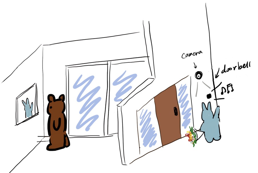
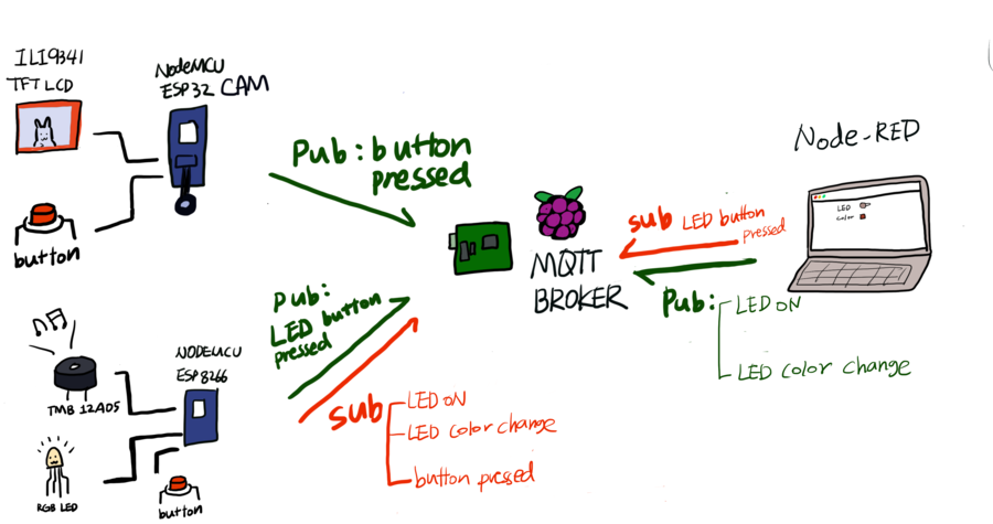
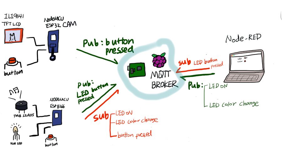
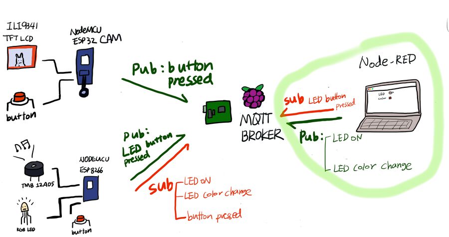
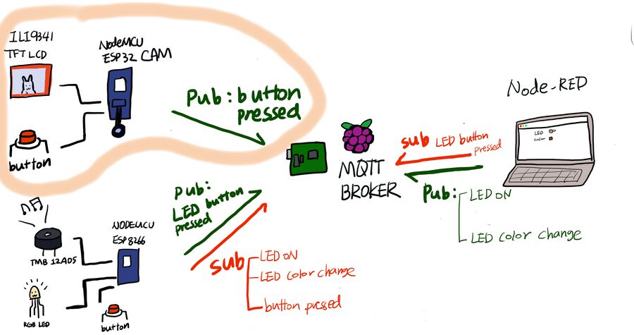
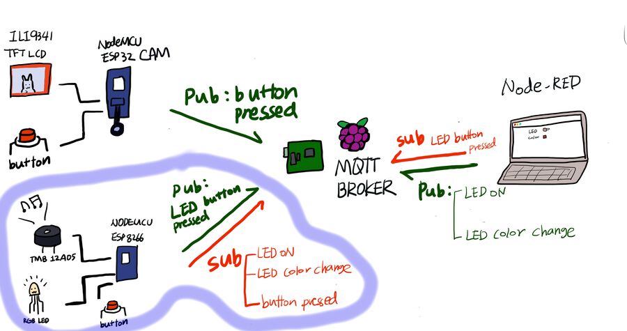
Before starting, I drew what I wanted to work on this week. Like the drawing below, I wanted to put a camera in front of the door. That would transmits images to the LCD screen inside of the house, when someone pressed the doorbell. And the buzzer will ring when the doorbell is pressed. Also, I wanted to control an RGB LED through Node-RED and MQTT.
And the image below is the technical structure of it. I wanted to connect the buzzer to the ESP32-CAM, but there was an issue that I couldn't resolve. Whenever ledcWriteTone(someValue, someValue); part was triggered, the camera stop working with an error meesage saying Timeout waiting for VSYNC. I spent so much time resolving it but I couldn't figure out why.
So, I connected the buzzer to the NodeMCU ESP8266 instead. The buzzer will ring when the ESP8266 receives a message through MQTT broker. For the MQTT broker, I installed Mosquitto Broker on a Raspberry Pi. The Raspberry Pi I had already has operating system installed, so I could start using it right away. Also, I have a 7 inch touch screen attached to the Pi, so it was very convenient to use it. I could just use it as if I was using a laptop.
I used my laptop to make a program on Node-RED and run the Node-RED UI. Also, there was a push button on the ESP32-CAM for the doorbell, and another one on the NodeMCU ESP8266 for turning on/off the LED. Now it's time to look at what I did for this project step-by-step.
Step 1. Install Mosquitto Broker on Raspberry Pi
To run a MQTT broker, I installed the Mosquitto Broker on the Raspberry Pi. You should have the Raspbian or Raspbian Lite operating system installed in your Raspberry Pi to do this. If you don't have one installed, you can check out this tutorial and follow the instructions. I already have an operating system installed on my Pi. Also, I have a 7 inch touch screen attached to the Pi, so I could use a keyboard to run commands in it. If you don't have a screen like me, you can use it headless and SSH into it. (Headless Raspberry Pi Setup)
Once you are ready to use your Pi, let's run the following commands to install the Mosquitto Broker.
pi@raspberry:~ $ sudo apt update
pi@raspberry:~ $ sudo apt install -y mosquitto mosquitto-clients # You’ll have to type Y and press Enter to confirm the installation
pi@raspberry:~ $ sudo systemctl enable mosquitto.service #  To make Mosquitto auto start on boot up
pi@raspberry:~ $ mosquitto -v
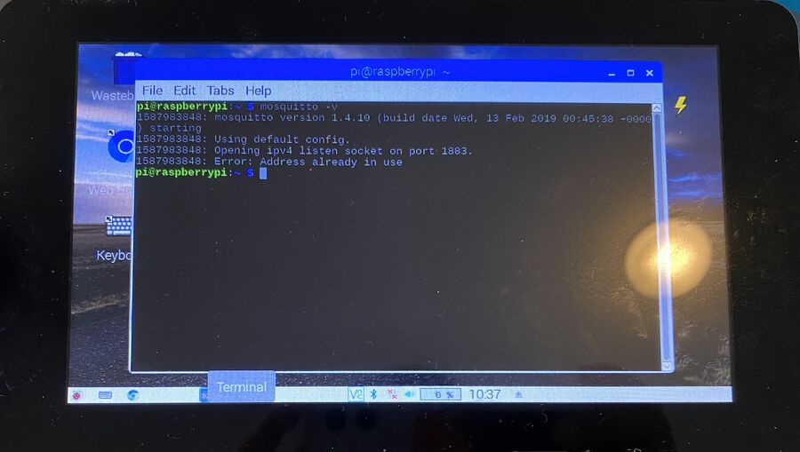
The Error: Address already in use warning message means that your Mosquitto Broker is already running, so don’t worry about that. To use Mosquitto broker later on your projects, you’ll need your Raspberry Pi IP address. To retrieve your Raspberry Pi IP address, type the next command in your terminal.
pi@raspberry:~ $ hostname -I
If you want to test if the Mosquitto broker is really working, you can follow this instruction.
Step 2. Getting Started with Node-RED
Getting Node-RED installed on the Raspberry Pi was pretty easy. You just need to run the following commands on the Pi terminal.
pi@raspberry:~ $ bash <(curl -sL https://raw.githubusercontent.com/node-red/raspbian-deb-package/master/resources/update-nodejs-and-nodered)
pi@raspberry:~ $ sudo systemctl enable nodered.service # To automatically run Node-RED when the Pi boots up
pi@raspberry:~ $ sudo reboot # restart the Pi to take effect
Once you finish the steps above, go to http://YOUR_RPi_IP_ADDRESS:1880 to see if the Node-RED is running. You can find the YOUR_RPi_IP_ADDRESS by typing hostname -I on the Pi. In my case, it was http://192.168.1.141:1880. I could've used the Node-RED on the Pi, but I used my laptop instead because I could control it better with my laptop.
Step 3. Getting Started with Node-RED Dashboard
Node-RED Dashboard is a module that provides a set of nodes in Node-RED to quickly create a live data dashboard. I had so much fun using it. I liked that I could make a nice looking UI simply by dragging, dropping and connecting nodes. Let's install it first and see how it works. You can install it through commands (like this), but I used the Node-RED UI to install it.
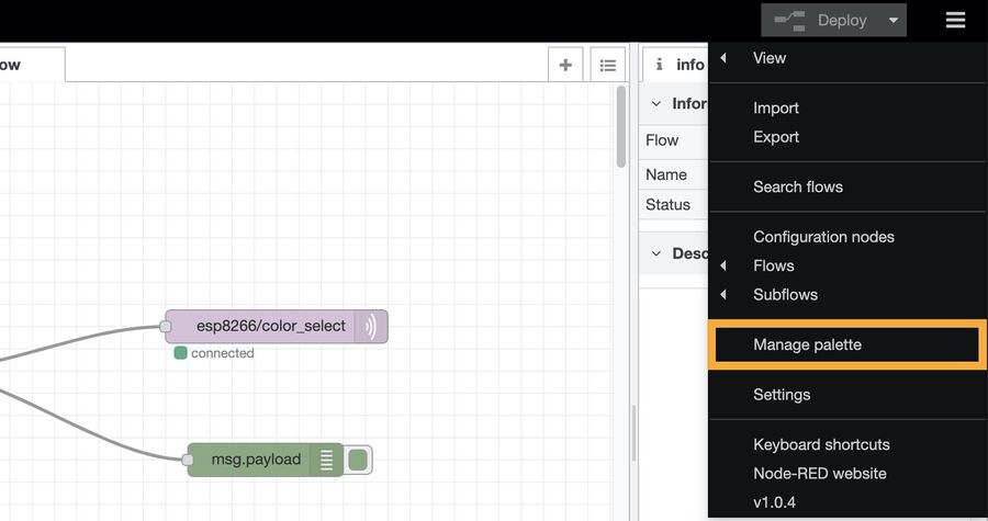
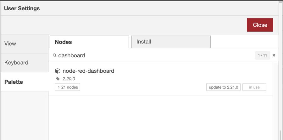
Click the Manage palette button and search dashboard, and install the package called node-red-dashboard. I found this way easier than using the terminal commands. Once you install it, now you can create a UI. You can learn more details about how to create a UI on this link. Once you create your own UI, you can go to http://Your_RPi_IP_address:1880/ui to see what you create.
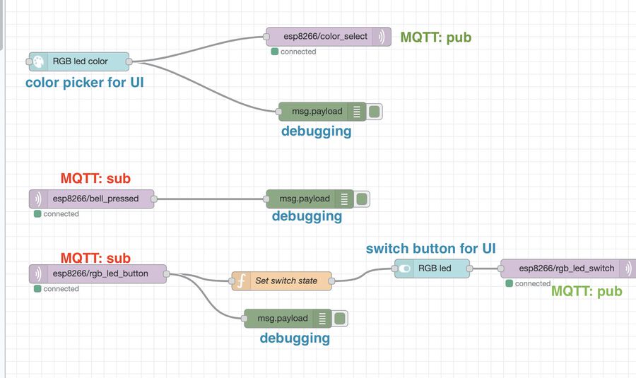
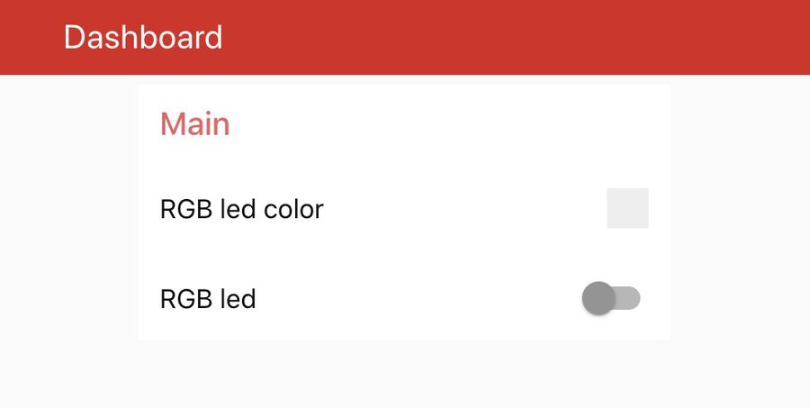
The photo on the left is the flow I created and on the right one is the UI. I also added some debugging nodes so that I could see the message coming through the MQTT. Also, it subscribes to the LED button pressed and the doorbell pressed topic. When the LED button is pressed, it updates the state of the switch on the UI so that there's no mismatches between them. Also when the doorbell is pressed, the buzzer connected to the NodeMCU will buzz because it's subscribing to that topic.
Step 4. ESP32-CAM + ILI9341 TFT LCD + MQTT
Now that the MQTT broker is ready, it's time to set up the hardware part and program it. It needs a lot of wiring (sketch download) as you can see from the photo below. I also connected the FTDI to program it and a push button to use as a doorbell.
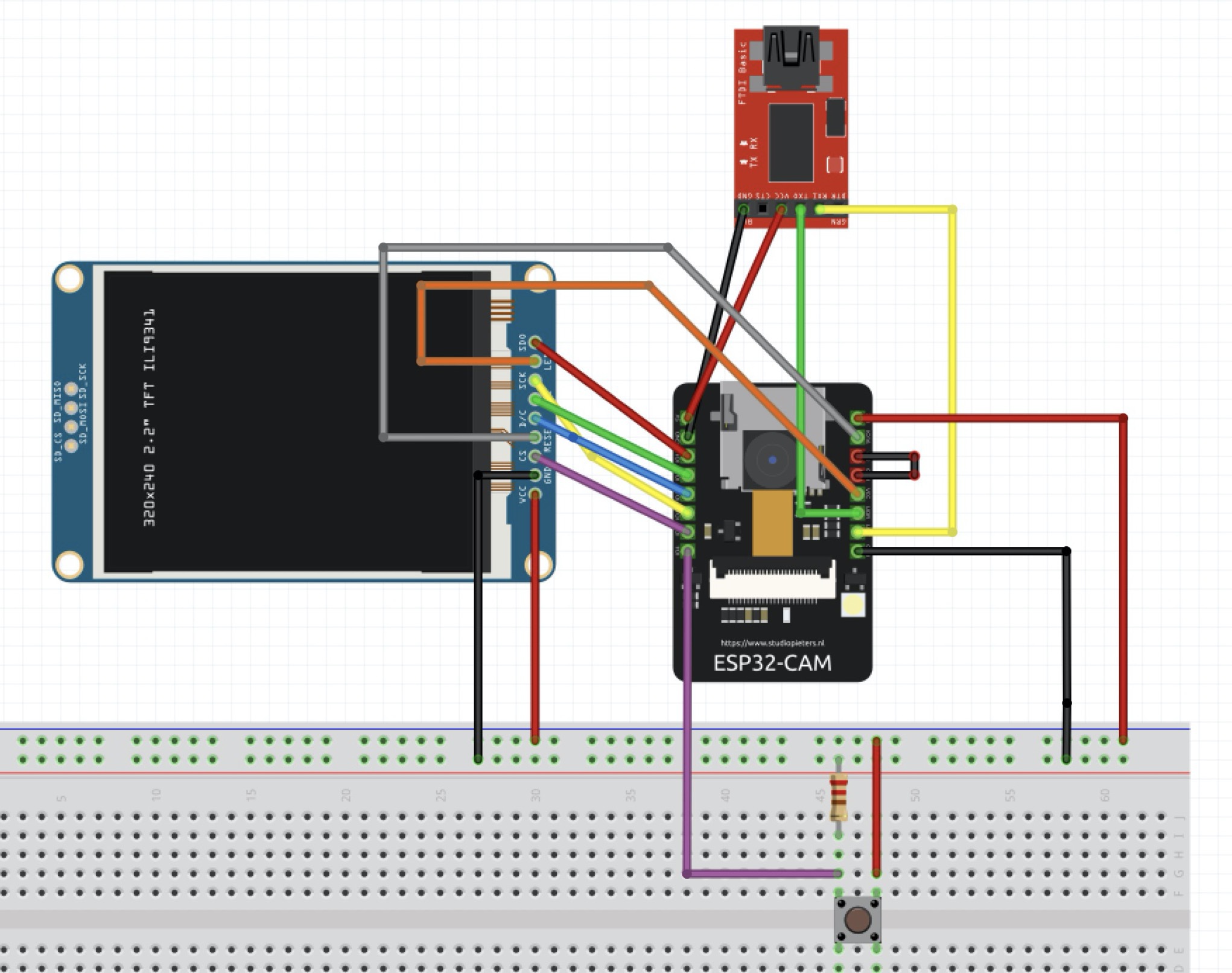
I followed this YouTube video to connect the LCD and the ESP32-CAM. I downloaded the TFT_eSPI library from the Arduino library manager. Then, I went to the TFT_eSPI library folder I just downloaded and opened the User_Setup.h file. From there, I modified some lines of code.
//#define TFT_MISO 19 // before
//#define TFT_MOSI 23
//#define TFT_SCLK 18
//#define TFT_CS   15  // Chip select control pin
//#define TFT_DC    2  // Data Command control pin
//#define TFT_RST   4  // Reset pin (could connect to RST pin)
//#define TFT_RST  -1  // Set TFT_RST to -1 if display RESET is connected to ESP32 board RST


#define TFT_MISO 12 // after
#define TFT_MOSI 13
#define TFT_SCLK 14
#define TFT_CS   2  // Chip select control pin
#define TFT_DC   15  // Data Command control pin
#define TFT_RST   16  // Reset pin (could connect to RST pin)
//#define TFT_RST  -1  // Set TFT_RST to -1 if display RESET is connected to ESP32 board RST
Then, I downloaded another library called TJpg_Decoder from the Arduino package manager. This is for showing the images into the display. Once installing it, I uploaded the code below to the ESP32-CAM board.
#include "esp_camera.h"
#define CAMERA_MODEL_AI_THINKER
#include "camera_pins.h"
#include <TJpg_Decoder.h>
#include <SPI.h>
#include <TFT_eSPI.h>

TFT_eSPI tft = TFT_eSPI();

//
// WARNING!!! Make sure that you have either selected ESP32 Wrover Module,
//            or another board which has PSRAM enabled
//


// example code from https://github.com/Bodmer/TJpg_Decoder/blob/master/examples/Flash_Jpg/Flash_Jpg.ino
bool tft_output(int16_t x, int16_t y, uint16_t w, uint16_t h, uint16_t* bitmap)
{
  // Stop further decoding as image is running off bottom of screen
  if ( y >= tft.height() ) return 0;

  // This function will clip the image block rendering automatically at the TFT boundaries
  tft.pushImage(x, y, w, h, bitmap);

  // This might work instead if you adapt the sketch to use the Adafruit_GFX library
  // tft.drawRGBBitmap(x, y, bitmap, w, h);

  // Return 1 to decode next block
  return 1;
}


void startCameraServer();

void setup() {
  Serial.begin(115200);
  delay(1000);

  tft.begin();
  // 0,2: portrait, 1,3: landscape

  Serial.println("INIT DISPLAY");
  tft.setRotation(3);
  tft.setTextColor(0xFFFF, 0x0000);
  tft.fillScreen(TFT_BLACK);


  TJpgDec.setJpgScale(1);
  TJpgDec.setSwapBytes(true);
  TJpgDec.setCallback(tft_output);
  Serial.println("INIT CAMERA");

  camera_config_t config;
  config.ledc_channel = LEDC_CHANNEL_0;
  config.ledc_timer = LEDC_TIMER_0;
  config.pin_d0 = Y2_GPIO_NUM;
  config.pin_d1 = Y3_GPIO_NUM;
  config.pin_d2 = Y4_GPIO_NUM;
  config.pin_d3 = Y5_GPIO_NUM;
  config.pin_d4 = Y6_GPIO_NUM;
  config.pin_d5 = Y7_GPIO_NUM;
  config.pin_d6 = Y8_GPIO_NUM;
  config.pin_d7 = Y9_GPIO_NUM;
  config.pin_xclk = XCLK_GPIO_NUM;
  config.pin_pclk = PCLK_GPIO_NUM;
  config.pin_vsync = VSYNC_GPIO_NUM;
  config.pin_href = HREF_GPIO_NUM;
  config.pin_sscb_sda = SIOD_GPIO_NUM;
  config.pin_sscb_scl = SIOC_GPIO_NUM;
  config.pin_pwdn = PWDN_GPIO_NUM;
  config.pin_reset = RESET_GPIO_NUM;
  config.xclk_freq_hz = 20000000;
  config.pixel_format = PIXFORMAT_JPEG;
  //init with high specs to pre-allocate larger buffers
  if (psramFound()) {
    config.frame_size = FRAMESIZE_QVGA; // 320x240
    config.jpeg_quality = 10;
    config.fb_count = 2;
  } else {
    config.frame_size = FRAMESIZE_SVGA;
    config.jpeg_quality = 12;
    config.fb_count = 1;
  }


  // camera init
  esp_err_t err = esp_camera_init(&config);
  if (err != ESP_OK) {
    Serial.printf("Camera init failed with error 0x%x", err);
    return;
  }

}
camera_fb_t* capture(){
  camera_fb_t *fb = NULL;
  esp_err_t res = ESP_OK;
  fb = esp_camera_fb_get();
  return fb;
}

void showingImage(){
  camera_fb_t *fb = capture();
  if(!fb || fb->format != PIXFORMAT_JPEG){
    Serial.println("Camera capture failed");
    esp_camera_fb_return(fb);
    return;
  }else{
    TJpgDec.drawJpg(0,0,(const uint8_t*)fb->buf, fb->len);
    esp_camera_fb_return(fb);
  }
}

void loop() {
  showingImage();
}
Once I uploaded the program, I pressed the reset button on the board, but I got an error message saying rst:0x1 (POWERON_RESET),boot:0x (DOWNLOAD_BOOT(UART0/UART1/SDIO_REI_REO_V2))
on the serial monitor. It turned out that I forgot to pull out the wire between the ground pin and IO0. After pulling the pin off from the ground, it worked well.
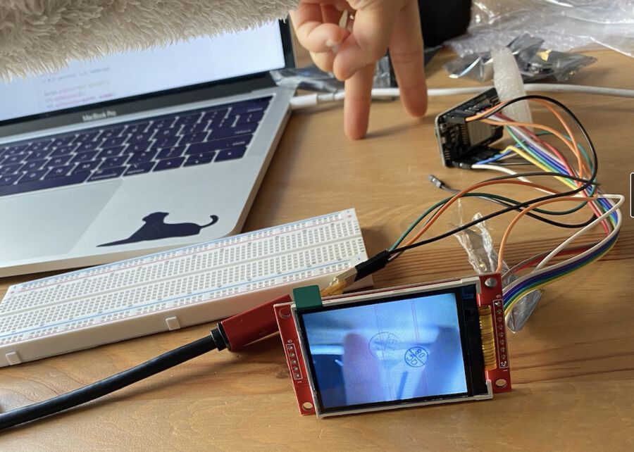
But there was one problem. I wanted to activate the screen only when the bell is pressed, for like 10 seconds. I googled if there were any ways to turn the backlight off of the screen, but the backlight LED part turned out to be hardwired. So I decided to display the idle screen during the inactive status, and show the camera images for 10 seconds only when the button was pressed.

To add an idle image, I used a bear paw image that I downloaded from the internet. Then, I converted the size to 320x240 (convert bear.png -resize 320x240\> bear.jpg), and converted it to a hex file from here. Then, I named the hexfile as idle.h and moved it into the same directory as my source code, and added #include "idle.h" line to my code.
#include "esp_camera.h"
#define CAMERA_MODEL_AI_THINKER
#include "camera_pins.h"
#include <TJpg_Decoder.h>
#include <SPI.h>
#include <TFT_eSPI.h>
#include "idle.h"

TFT_eSPI tft = TFT_eSPI();

const int buttonPin = 4;    // the number of the pushbutton pin
int buttonState;
int lastButtonState = LOW;
unsigned long lastDebounceTime = 0;  // the last time the output pin was toggled
unsigned long debounceDelay = 50;    // the debounce time; increase if the output flickers
bool isNormalMode = true;
int screenOnCountDown = 0;
bool screenOn = false;
//
// WARNING!!! Make sure that you have either selected ESP32 Wrover Module,
//            or another board which has PSRAM enabled
//


// example code from https://github.com/Bodmer/TJpg_Decoder/blob/master/examples/Flash_Jpg/Flash_Jpg.ino
bool tft_output(int16_t x, int16_t y, uint16_t w, uint16_t h, uint16_t* bitmap)
{
  // Stop further decoding as image is running off bottom of screen
  if ( y >= tft.height() ) return 0;

  // This function will clip the image block rendering automatically at the TFT boundaries
  tft.pushImage(x, y, w, h, bitmap);

  // This might work instead if you adapt the sketch to use the Adafruit_GFX library
  // tft.drawRGBBitmap(x, y, bitmap, w, h);

  // Return 1 to decode next block
  return 1;
}


void startCameraServer();

void setup() {
  pinMode(buttonPin, INPUT);

  Serial.begin(115200);
  delay(1000);

  tft.begin();
  // 0,2: portrait, 1,3: landscape

  Serial.println("INIT DISPLAY");
  tft.setRotation(3);
  tft.setTextColor(0xFFFF, 0x0000);
  tft.fillScreen(TFT_BLACK);


  TJpgDec.setJpgScale(1);
  TJpgDec.setSwapBytes(true);
  TJpgDec.setCallback(tft_output);
  Serial.println("INIT CAMERA");

  camera_config_t config;
  config.ledc_channel = LEDC_CHANNEL_0;
  config.ledc_timer = LEDC_TIMER_0;
  config.pin_d0 = Y2_GPIO_NUM;
  config.pin_d1 = Y3_GPIO_NUM;
  config.pin_d2 = Y4_GPIO_NUM;
  config.pin_d3 = Y5_GPIO_NUM;
  config.pin_d4 = Y6_GPIO_NUM;
  config.pin_d5 = Y7_GPIO_NUM;
  config.pin_d6 = Y8_GPIO_NUM;
  config.pin_d7 = Y9_GPIO_NUM;
  config.pin_xclk = XCLK_GPIO_NUM;
  config.pin_pclk = PCLK_GPIO_NUM;
  config.pin_vsync = VSYNC_GPIO_NUM;
  config.pin_href = HREF_GPIO_NUM;
  config.pin_sscb_sda = SIOD_GPIO_NUM;
  config.pin_sscb_scl = SIOC_GPIO_NUM;
  config.pin_pwdn = PWDN_GPIO_NUM;
  config.pin_reset = RESET_GPIO_NUM;
  config.xclk_freq_hz = 20000000;
  config.pixel_format = PIXFORMAT_JPEG;
  //init with high specs to pre-allocate larger buffers
  if (psramFound()) {
    config.frame_size = FRAMESIZE_QVGA; // 320x240
    config.jpeg_quality = 10;
    config.fb_count = 2;
  } else {
    config.frame_size = FRAMESIZE_SVGA;
    config.jpeg_quality = 12;
    config.fb_count = 1;
  }


  // camera init
  esp_err_t err = esp_camera_init(&config);
  if (err != ESP_OK) {
    Serial.printf("Camera init failed with error 0x%x", err);
    return;
  }

}
camera_fb_t* capture() {
  camera_fb_t *fb = NULL;
  esp_err_t res = ESP_OK;
  fb = esp_camera_fb_get();
  return fb;
}

void showingImage() {
  camera_fb_t *fb = capture();
  if (!fb || fb->format != PIXFORMAT_JPEG) {
    Serial.println("Camera capture failed");
    esp_camera_fb_return(fb);
    return;
  } else {
    TJpgDec.drawJpg(0, 0, (const uint8_t*)fb->buf, fb->len);
    esp_camera_fb_return(fb);
  }
}

void loop() {
  buttonEvent();
  if (screenOnCountDown > 0) {
    showingImage();
    Serial.println(screenOnCountDown);
    screenOnCountDown--;
  } else {
      TJpgDec.drawJpg(0, 0, idle, sizeof(idle));
  }
}

void buttonEvent() {
  int reading = digitalRead(buttonPin);
  if (reading != lastButtonState) {
    lastDebounceTime = millis();
  }

  if ((millis() - lastDebounceTime) > debounceDelay) {
    if (reading != buttonState) {
      buttonState = reading;

      if (buttonState == HIGH) {
        isNormalMode = !isNormalMode;
        //Additional Code
        screenOnCountDown = 100;
      }
    }
  }
  lastButtonState = reading;
}
I tried to add a buzzer to it, but whenever the buzzer part got run (ledcWriteTone(0, 800);), the image transfering from the camera to screen failed. The error message kept saying Timeout waiting for VSYNC, and I couldn't figure out why.
void playTone() {
  ledcWriteTone(0, 800);
}

void stopPlayingTone() {
  ledcWrite(0, 0);
}
I struggled for a while, and moved on from it. As a workaround, I decided to add a buzzer to the NodeMCU board and let the button and buzzer communicate through MQTT. To do that, I added the code for the WiFi and MQTT client.
#include "esp_camera.h"
#define CAMERA_MODEL_AI_THINKER
#include "camera_pins.h"
#include <TJpg_Decoder.h>
#include <SPI.h>
#include <TFT_eSPI.h>
#include "idle.h"

#include <WiFi.h>
#include <PubSubClient.h>
#include "Arduino.h"


// Replace the next variables with your SSID/Password combination
const char* ssid     = "YOUR_WIFI_SSID";
const char* password = "YOUR_WIFI_PASSWORD";

// Add your MQTT Broker IP address:
// To see the IP address of your Raspberry pi, type hostname -I
const char* mqtt_server = "192.168.1.141";


WiFiClient espClient;
PubSubClient client(espClient);


TFT_eSPI tft = TFT_eSPI();

const int buttonPin = 4;    // the number of the pushbutton pin
int buttonState;
int lastButtonState = LOW;

bool isNormalMode = true;
int screenOnCountDown = 0;
bool screenOn = false;
//
// WARNING!!! Make sure that you have either selected ESP32 Wrover Module,
//            or another board which has PSRAM enabled
//


// example code from https://github.com/Bodmer/TJpg_Decoder/blob/master/examples/Flash_Jpg/Flash_Jpg.ino
bool tft_output(int16_t x, int16_t y, uint16_t w, uint16_t h, uint16_t* bitmap)
{
  // Stop further decoding as image is running off bottom of screen
  if ( y >= tft.height() ) return 0;

  // This function will clip the image block rendering automatically at the TFT boundaries
  tft.pushImage(x, y, w, h, bitmap);

  // This might work instead if you adapt the sketch to use the Adafruit_GFX library
  // tft.drawRGBBitmap(x, y, bitmap, w, h);

  // Return 1 to decode next block
  return 1;
}


void startCameraServer();

void setup() {
  pinMode(buttonPin, INPUT);

  Serial.begin(115200);
  delay(1000);

  setup_wifi();
  client.setServer(mqtt_server, 1883);
//  client.setCallback(callback);

  tft.begin();
  // 0,2: portrait, 1,3: landscape

  Serial.println("INIT DISPLAY");
  tft.setRotation(3);
  tft.setTextColor(0xFFFF, 0x0000);
  tft.fillScreen(TFT_BLACK);


  TJpgDec.setJpgScale(1);
  TJpgDec.setSwapBytes(true);
  TJpgDec.setCallback(tft_output);
  Serial.println("INIT CAMERA");

  camera_config_t config;
  config.ledc_channel = LEDC_CHANNEL_0;
  config.ledc_timer = LEDC_TIMER_0;
  config.pin_d0 = Y2_GPIO_NUM;
  config.pin_d1 = Y3_GPIO_NUM;
  config.pin_d2 = Y4_GPIO_NUM;
  config.pin_d3 = Y5_GPIO_NUM;
  config.pin_d4 = Y6_GPIO_NUM;
  config.pin_d5 = Y7_GPIO_NUM;
  config.pin_d6 = Y8_GPIO_NUM;
  config.pin_d7 = Y9_GPIO_NUM;
  config.pin_xclk = XCLK_GPIO_NUM;
  config.pin_pclk = PCLK_GPIO_NUM;
  config.pin_vsync = VSYNC_GPIO_NUM;
  config.pin_href = HREF_GPIO_NUM;
  config.pin_sscb_sda = SIOD_GPIO_NUM;
  config.pin_sscb_scl = SIOC_GPIO_NUM;
  config.pin_pwdn = PWDN_GPIO_NUM;
  config.pin_reset = RESET_GPIO_NUM;
  config.xclk_freq_hz = 20000000;
  config.pixel_format = PIXFORMAT_JPEG;
  //init with high specs to pre-allocate larger buffers
  if (psramFound()) {
    config.frame_size = FRAMESIZE_QVGA; // 320x240
    config.jpeg_quality = 10;
    config.fb_count = 2;
  } else {
    config.frame_size = FRAMESIZE_SVGA;
    config.jpeg_quality = 12;
    config.fb_count = 1;
  }


  // camera init
  esp_err_t err = esp_camera_init(&config);
  if (err != ESP_OK) {
    Serial.printf("Camera init failed with error 0x%x", err);
    return;
  }

}
camera_fb_t* capture() {
  camera_fb_t *fb = NULL;
  esp_err_t res = ESP_OK;
  fb = esp_camera_fb_get();
  return fb;
}

void setup_wifi() {
  delay(10);
  // We start by connecting to a WiFi network
  Serial.println();
  Serial.print("Connecting to ");
  Serial.println(ssid);

  WiFi.begin(ssid, password);

  while (WiFi.status() != WL_CONNECTED) {
    delay(500);
    Serial.print(".");
  }

  Serial.println("");
  Serial.println("WiFi connected");
  Serial.println("IP address: ");
  Serial.println(WiFi.localIP());
}

void showingImage() {
  camera_fb_t *fb = capture();
  if (!fb || fb->format != PIXFORMAT_JPEG) {
    Serial.println("Camera capture failed");
    esp_camera_fb_return(fb);
    return;
  } else {
    TJpgDec.drawJpg(0, 0, (const uint8_t*)fb->buf, fb->len);
    esp_camera_fb_return(fb);
  }
}


void reconnect() {
  // Loop until we're reconnected
  while (!client.connected()) {
    Serial.print("Attempting MQTT connection...");
    // Attempt to connect
    if (client.connect("ESP32CAM")) {
      Serial.println("connected");
    } else {
      Serial.print("failed, rc=");
      Serial.print(client.state());
      Serial.println(" try again in 5 seconds");
      // Wait 5 seconds before retrying
      delay(5000);
    }
  }
}

void loop() {

  if (!client.connected()) {
    reconnect();
  }
  client.loop();

  buttonEvent();

  if (screenOnCountDown > 0) {
    showingImage();
    Serial.println(screenOnCountDown);
    screenOnCountDown--;
  } else {
    TJpgDec.drawJpg(0, 0, idle, sizeof(idle));
  }
}

unsigned long lastDebounceTime = 0;  // the last time the output pin was toggled
unsigned long debounceDelay = 50;    // the debounce time; increase if the output flickers


void buttonEvent() {
  int reading = digitalRead(buttonPin);
  if (reading != lastButtonState) {
    lastDebounceTime = millis();
  }

  if ((millis() - lastDebounceTime) > debounceDelay) {
    if (reading != buttonState) {
      buttonState = reading;

      if (buttonState == HIGH) {
        client.publish("esp8266/bell_pressed", "1");
        isNormalMode = !isNormalMode;
        screenOnCountDown = 100;
      }
    }
  }
  lastButtonState = reading;
}
When the button is pressed, it will publish the button pressed event (client.publish("esp8266/bell_pressed", "1");). Now it's time to work on the second board, NodeMCU ESP8266, so that it can subscirbe to the bell_pressed action and ring the buzzer.
Step 5. NodeMCU ESP8266 + buzzer + RGB LED + button + MQTT Pub/Sub
Finally the last part of this long project. The buzzer will buzz when it gets the message esp8266/bell_pressed from the button on the ESP32-CAM board. (I think I should've named this topic better than this, since it started getting me confused.)
One thing you should keep in mind is in client.connect(SOME_STRING) part, the SOME_STRING part should be different for each board. Otherwise, the board connected later will keep being disconnected and connected.
Another thing is not to use a resistor more than 200 Ohm for the buzzer. At first, I used a 10k Ohm resistor without thinking, and I couldn't hear anything from the buzzer. I thought that the connection was wrong, but it turned out that the buzzer sound was very quiet because of the high resistor. After switching it to 200 Ohm, it worked well.
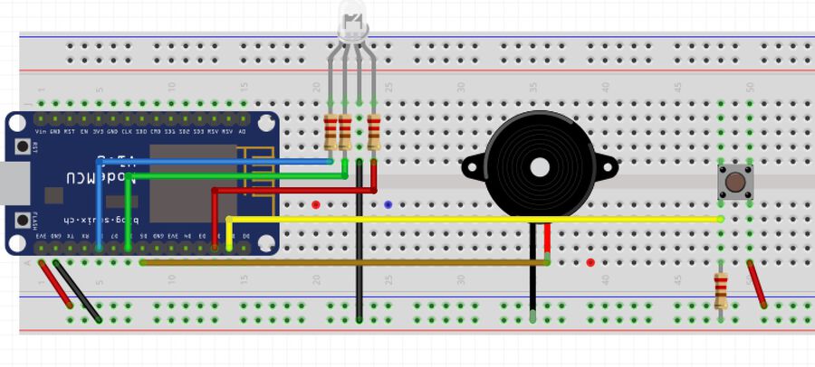
The button on this sketch is for turning on/off the LED. Also, whenever you press the button, it publishes client.publish("esp8266/rgb_led_button", "1");, and it updates the switch on the Node-RED UI. This is for preventing the mismatches of the status between the LED and the switch on the UI. The board subscribes client.subscribe("esp8266/rgb_led_switch");, so if there's an update from the UI, it changes the status of LED as well as turns the light on.
Lastly, the board subscribes the client.subscribe("esp8266/color_select"). There is a color picker on the Node-RED UI and it listens to that and changes the color of LED.
#include <ESP8266WiFi.h>
#include <PubSubClient.h>

const char* ssid     = "YOUR_WIFI_SSID";
const char* password = "YOUR_WIFI_PASSWORD";
const char* mqttServer = "192.168.1.141";

// LED Pin
int red_light_pin = 4;
int green_light_pin = 12;
int blue_light_pin = 15;

int r = 0;
int g = 0;
int b = 0;

int buttonPin = 5;
int rgbLedState = LOW;   // q. can i unset this?
int rgbLedButtonState; // the current rgbLedReading from the input pin
int rgbLastButtonState = LOW; // the previous rgbLedReading from the input pin
unsigned long lastDebounceTime = 0; // the last time the output pin was toggled
unsigned long debounceDelay = 50;


const int buzzer = 14;
bool buzzerOn = false;
int length = 15; // the number of notes
char notes[] = "ccggaagffeeddc "; // a space represents a rest
int beats[] = { 1, 1, 1, 1, 1, 1, 2, 1, 1, 1, 1, 1, 1, 2, 4 };
int tempo = 300;


WiFiClient espClient;
PubSubClient client(espClient);

void setup() {

  Serial.begin(115200);
  pinMode(buzzer, OUTPUT);

  pinMode(red_light_pin, OUTPUT);
  pinMode(green_light_pin, OUTPUT);
  pinMode(blue_light_pin, OUTPUT);

  pinMode(buttonPin, INPUT);

  digitalWrite(red_light_pin, 0);
  digitalWrite(green_light_pin, 0);
  digitalWrite(blue_light_pin, 0);

  WiFi.begin(ssid, password);

  while (WiFi.status() != WL_CONNECTED) {
    delay(500);
    Serial.println("Connecting to WiFi..");
  }
  Serial.println("Connected to the WiFi network");

  client.setServer(mqttServer, 1883);
  client.setCallback(callback);

  while (!client.connected()) {
    Serial.println("Connecting to MQTT...");

    if (client.connect("ESP8266Client")) {
      Serial.println("connected");

    } else {
      Serial.print("failed, rc=");
      Serial.print(client.state());
      Serial.println(" try again in 5 seconds");
      // Wait 5 seconds before retrying
      delay(5000);
    }
  }
  // Subscribe
  client.subscribe("esp8266/bell_pressed");
  client.subscribe("esp8266/color_select");
  client.subscribe("esp8266/rgb_led_switch");

}

void callback(char* topic, byte* payload, unsigned int length) {

  Serial.print("Message arrived in topic: ");
  Serial.println(topic);

  Serial.print("Message:");
  String messageTemp;
  for (int i = 0; i < length; i++) {
    Serial.print((char)payload[i]);
    messageTemp += (char)payload[i];
  }


  if (String(topic) == "esp8266/bell_pressed") {
    if (messageTemp == "1") {
      Serial.println("buzz");
      buzzerOn = true;
    }
  } else if (String(topic) == "esp8266/color_select") {
    long number = (long) strtol( &messageTemp[0], NULL, 16);
    r = number >> 16;
    g = number >> 8 & 0xFF;
    b = number & 0xFF;

    Serial.print("red is ");
    Serial.println(r);
    Serial.print("green is ");
    Serial.println(g);
    Serial.print("blue is ");
    Serial.println(b);

    RGB_color(r, g, b);
    rgbLedState = true;
    client.publish("esp8266/rgb_led_button", "1");

  } else if (String(topic) == "esp8266/rgb_led_switch") {
    if (messageTemp == "true") {
      if (r == 0 && g == 0 && b == 0) {
        RGB_color(255, 255, 255);
      } else {
        RGB_color(r, g, b);
      }
      rgbLedState = true;

    } else if (messageTemp == "false") {
      RGB_color(0, 0, 0);
      rgbLedState = false;
    }
  }


}

void reconnect() {

  while (!client.connected()) {
    Serial.println("Connecting to MQTT...");

    if (client.connect("ESP8266")) {
      Serial.println("connected");


    } else {
      Serial.print("failed, rc=");
      Serial.print(client.state());
      Serial.println(" try again in 5 seconds");
      // Wait 5 seconds before retrying
      delay(5000);
    }
  }
  // Subscribe
  client.subscribe("esp8266/bell_pressed");
  client.subscribe("esp8266/color_select");
  client.subscribe("esp8266/rgb_led_switch");
}

void loop() {
  if (!client.connected()) {
    reconnect();
  }


  if (buzzerOn) {
    for (int i = 0; i < length; i++) {
      if (notes[i] == ' ') {
        delay(beats[i] * tempo); // rest
      } else {
        playNote(notes[i], beats[i] * tempo);
      }

      // pause between notes
      delay(tempo / 2);
    }
    buzzerOn = false;
  }

  ////////////////// debouunce part start
  int rgbLedReading = digitalRead(buttonPin);
  if (rgbLedReading != rgbLastButtonState) {
    lastDebounceTime = millis();
  }


  if ((millis() - lastDebounceTime) + debounceDelay) {
    if (rgbLedReading != rgbLedButtonState) {
      rgbLedButtonState = rgbLedReading;

      // only toggle the LED if the new button state is HIGH
      if (rgbLedButtonState == HIGH) {
        rgbLedState = !rgbLedState;

        if (rgbLedState) {
          if (r == 0 && g == 0 && b == 0) {
            RGB_color(255, 255, 255);
          } else {
            RGB_color(r, g, b);
          }
        client.publish("esp8266/rgb_led_button", "1");
        } else {
          RGB_color(0, 0, 0);
          client.publish("esp8266/rgb_led_button", "0");
        }
      }
    }
  }

  rgbLastButtonState = rgbLedReading;
  ///////////////////////// debouunce part end

  client.loop();
}


void playTone(int tone, int duration) {
  for (long i = 0; i < duration * 1000L; i += tone * 2) {
    digitalWrite(buzzer, HIGH);
    delayMicroseconds(tone);
    digitalWrite(buzzer, LOW);
    delayMicroseconds(tone);
  }
}

// buzzer song from https://elearn.ellak.gr/mod/book/tool/print/index.php?id=2815&chapterid=1163

void playNote(char note, int duration) {
  char names[] = { 'c', 'd', 'e', 'f', 'g', 'a', 'b', 'C' };
  int tones[] = { 1915, 1700, 1519, 1432, 1275, 1136, 1014, 956 };

  // play the tone corresponding to the note name
  for (int i = 0; i < 8; i++) {
    if (names[i] == note) {
      playTone(tones[i], duration);
    }
  }
}

void RGB_color(int red_light_value, int green_light_value, int blue_light_value)
{
  analogWrite(red_light_pin, red_light_value);
  analogWrite(green_light_pin, green_light_value);
  analogWrite(blue_light_pin, blue_light_value);
}
Done! Let's see how it can be integrated to the house.
Scenario 1. A rabbit's visit
When the push button is pressed, the camera gets awake from the idle mode (the bear paw image), and it shows the images sent from the ESP32-CAM.
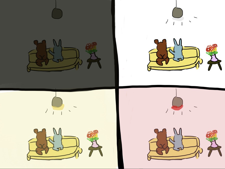
Scenario 2. Disco time
You can turn on and off the light and change the color of it from the Node-RED UI. Also, when you press the push button, the switch on the UI will be updated as well.
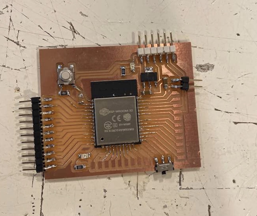
Updated - June 28th
Below is a video of the doorbell working with the PCB board I made. It's from my final project.
Group assignment
This week's group assignment is to compare as many tool options as possible. Each of us experimented with different tools and shared about them through Zoom meeting.
-Harm: Scratch for Arduino (S4A), ArduBlock, Minibloq, mBlocks
-Tessel: Processing
-Nathan: PySerial, TKinter
-Hyejin: Node-RED
The detailed group assignment documentation can be found here.