-
01. Principles and practices
-
02. Project management
-
03. Computer-Aided design
-
04. Computer controlled cutting
-
05. Electronics production
-
06. 3D Scanning and printing
-
07. Electronics design
-
08. Computer controlled machining
-
09. Embedded programming
-
10. Input devices
-
Assignment
-
Individual assignment
- RCWL-0516
- ESP32-CAM
1. Design a new ATtiny1614 board
2. Program Arduino Uno for RCWL-0516
3. Create a PyQt5 program for the RCWL-0516
4. Program the ESP32-CAM with the FTDI cable
5. Add a camera screen to the PyQt program
6. Program ATtiny1614 board with Arduino Uno
7. Make a new ATtiny1614 board
-
Group assignment
-
Attachments
-
Useful links
-
-
11. Applications and implications
-
12. Output devices
-
13. Interface and application programming
-
14. Invention, intellectual property and income
-
15. Networking and communications
-
16. Molding and casting
-
17. Wildcard week
-
18. Machine design
-
19. Project development
-
Glossary
Week 10. Input devices
April 1, 2020
Assignment
Group assignment
- Probe an input device's analog levels and digital signals
Individual assignment
- Measure something: add a sensor to a microcontroller board that you have designed and read from it
Individual assignment
For this week's assignment, I decided to use an RCWL-0516 proximity sensor and an ESP32-CAM. I wanted to make a motion sensored light and security system for the final project. The list below is the summary of what I did this week.
I designed a new board with an ATtiny1614, so that I could add some input devices. Henk milled the board for me because I couldn't go to the lab because of the coronavirus. While waiting for Henk to mill the new board, I programmed the sensor with an Arduino Uno board to see if it would work. Also, I made a program with PyQt to see the status of the proximity sensor and the video stream coming from the ESP32 camera module. Once I got the new PCB, I soldered the board and the sensor. Then, I downloaded the program I wrote into the ATtiny1614 board. This is the brief summary of what I did this week. Let's take a look step-by-step.
RCWL-0516
RCWL-0516 is a doppler radar microwave motion sensor module which can act as an alternative to a PIR motion sensor. The forward side of the board is the side with components. This side should face the objects being detected.
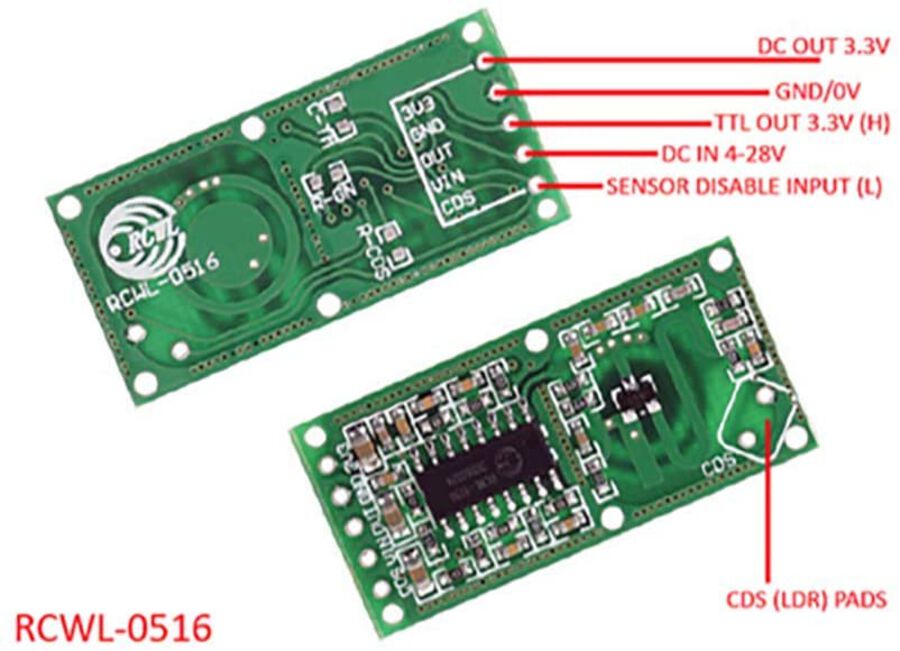
VIN - 4V - 28V DC power supply input
CDS - Sensor disable input (low = disable) (For LDR sensors)
GND - Ground
3V - DC output (100 mA maximum)
OUTPUT - HIGH /LOW(3.3 V) (according to the motion detection)
The CDS pin lets you add an LDR (light dependent resistor) to the board, which allows for operation in low power mode so that the sensor only activates in the dark.
ESP32-CAM
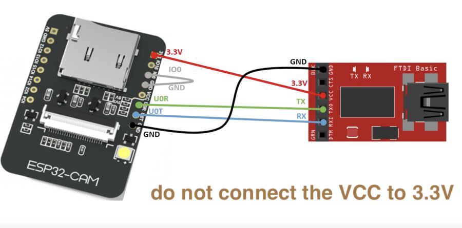
The ESP32-CAM is a very small camera module with the ESP32-S chip that costs approximately $10. Besides the OV2640 camera, and several GPIOs to connect peripherals, it also features a microSD card slot that can be useful to store images taken with the camera or to store files to serve to clients. The ESP32-CAM doesn't come with a USB connector, so you need an FTDI programmer to upload code through the U0R and U0T pins (serial pins).
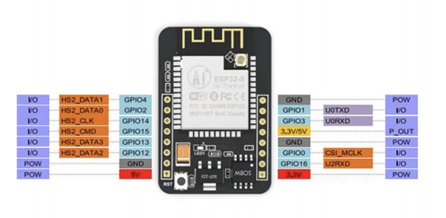
There are three GND pins and two pins for power: either 3.3V or 5V. GPIO 1 and GPIO 3 are the serial pins. You need these pins to upload code to your board. Additionally, GPIO 0 also plays an important role, since it determines whether the ESP32 is in flashing mode or not. When GPIO 0 is connected to GND, the ESP32 is in flashing mode. (more details on ESP32-CAM)
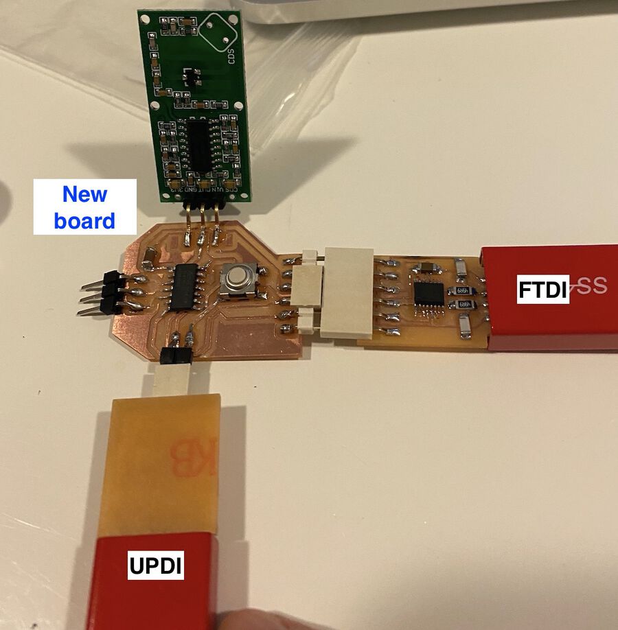
1. Design a new ATtiny1614 board
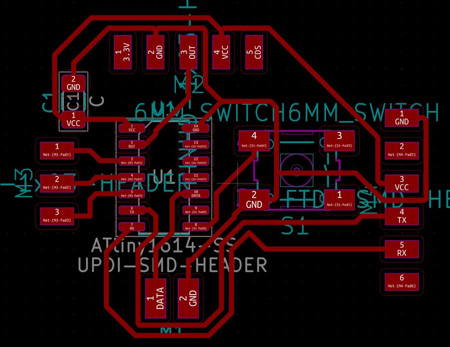
I drew a simple ATtiny1614 board and I added some pads for connecting the RCWL-0516 headers. I also added three GPIO headers so that I can add some LEDs later.

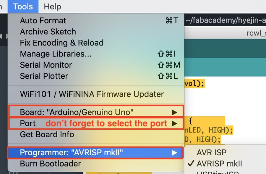
2. Program Arduino Uno for RCWL-0516
Since I had to wait for the board to be milled, I decided to experiment with the Arduino board and the sensor. I connected the Uno board with the RCWL-0516 like the image below. I only used the GND, OUT, VIN pin headers.
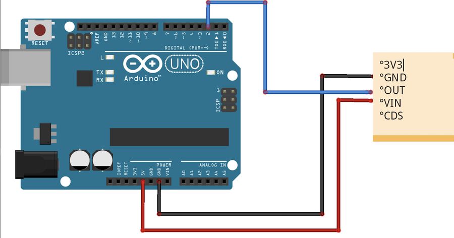
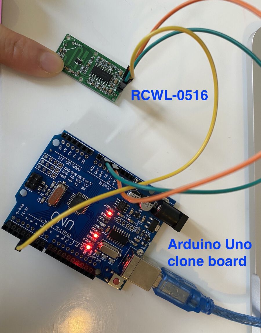
One thing I did differently from the image on the left is that I used pin 4 from the Uno board, because there was something stuck in the pin 2 hole. Then, I uploaded the code using the Arduino IDE. The code is pretty simple because I just wanted to see how the sensor works. It prints out 1 if it's active, and 0 when it's not.
int sensorInput = 4;     // RCWL-0516 Input Pin for Arduino
int sensorval = 0;  // RCWL-0516 Sensor Value

void setup() {
  Serial.begin(9600);
  pinMode (sensorInput, INPUT);
}

void loop(){
  sensorval = digitalRead(sensorInput);
  Serial.println(sensorval);
}
It worked well. The sensor was so sensitive that it even responded to a very small movement I made.
3. Create a PyQt5 program for the RCWL-0516
I really liked the hello.RCWL-0516 program written with Tkinter, and I wanted to make a program something like this. I decided to use PyQt instead of Tkinter just because I'm more familiar with it.
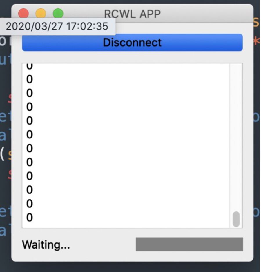
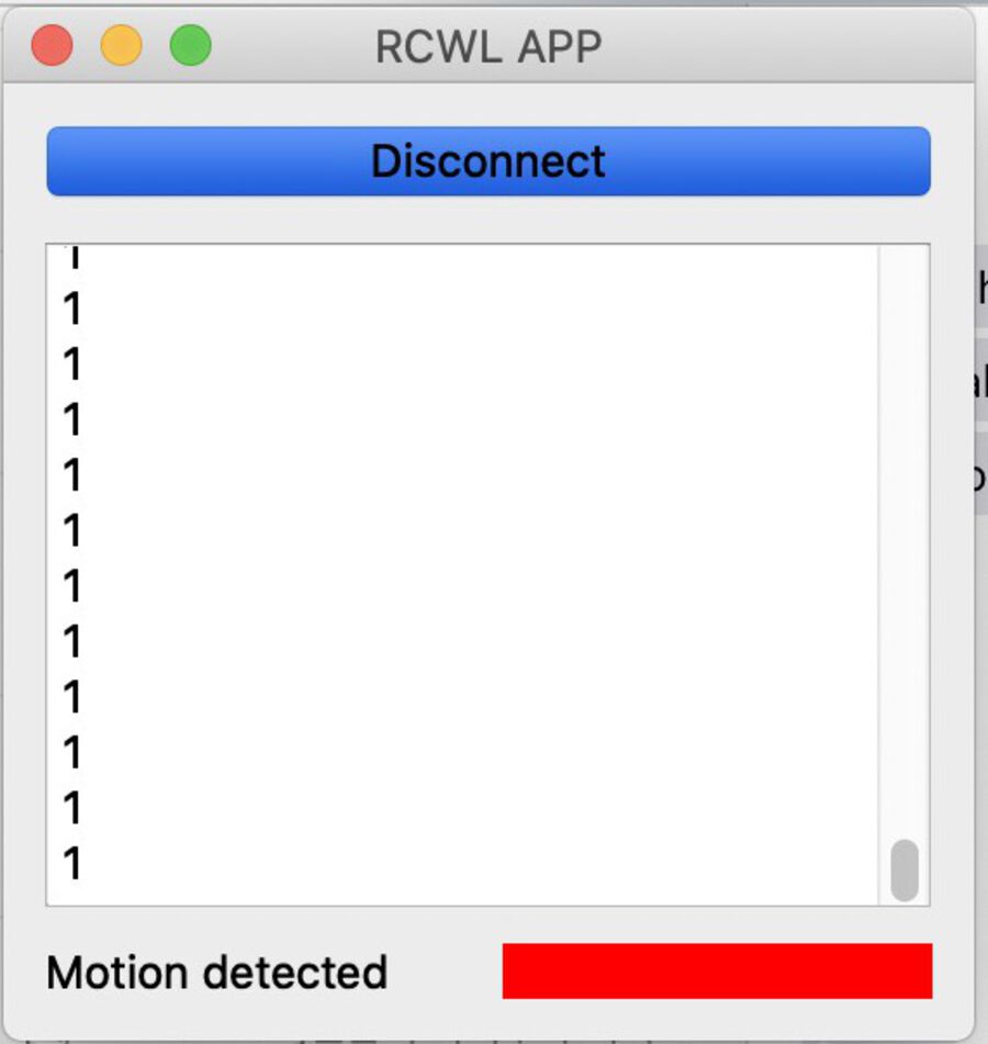
It shows "Waiting..."" and the grey square when there's no motion detected, and shows "Motion detected!" and the red square when any motion is detected.
from PyQt5 import QtCore, QtSerialPort
from PyQt5.QtWidgets import *
from PyQt5.QtCore import *
from PyQt5.QtGui import *

# Only needed for access to command line arguments
import sys

class Color(QWidget):

    def __init__(self, color, *args, **kwargs):
        super(Color, self).__init__(*args, **kwargs)
        self.setAutoFillBackground(True)

        palette = self.palette()
        palette.setColor(QPalette.Window, QColor(color))
        self.setPalette(palette)
    def set_color(self, color):
        palette = self.palette()

        palette.setColor(QPalette.Window, QColor(color))
        self.setPalette(palette)


# Subclass QMainWindow to customise your application's main window
class MainWindow(QMainWindow):

    def __init__(self, *args, **kwargs):
        super(MainWindow, self).__init__(*args, **kwargs)

        self.setWindowTitle("RCWL APP")

        layout1 = QVBoxLayout()
        layout2 = QHBoxLayout()

        self.connect_btn = QPushButton(
            text="Connect",
            checkable=True,
            clicked=self.on_toggled
        )

        self.output_te = QTextEdit(readOnly=True)
        self.outputLabel = QLabel("Hi there!")
        self.color = Color("grey")

        layout1.addWidget(self.connect_btn)
        layout1.addWidget(self.output_te)
        layout2.addWidget(self.outputLabel)
        layout2.addWidget(self.color)
        layout1.addLayout(layout2)

        widget = QWidget()
        widget.setLayout(layout1)
        self.setCentralWidget(widget)
        self.serial = QtSerialPort.QSerialPort(
            app.arguments()[1],
            baudRate=QtSerialPort.QSerialPort.Baud9600,
            readyRead=self.receive
        )

    @QtCore.pyqtSlot()
    def receive(self):
        while self.serial.canReadLine():
            text = self.serial.read(1).decode()
            text = text.rstrip('\r\n')
            if bool(text):
                self.output_te.append(text)
                self.outputLabel.setText("Motion detected" if text == "1" else "Waiting...")
                self.color.set_color("red"if text == "1" else "grey")


    @QtCore.pyqtSlot(bool)
    def on_toggled(self, checked):
        self.connect_btn.setText("Disconnect" if checked else "Connect")
        if checked:
            if not self.serial.isOpen():
                if not self.serial.open(QtCore.QIODevice.ReadWrite):
                    self.connect_btn.setChecked(False)
        else:
            self.outputLabel.setText("Hi there!")
            self.color.set_color("grey")
            self.serial.close()

if __name__ == '__main__':
    import sys
    if (len(sys.argv) != 2):
        print("command line: rcwl_monitor.py serial_port")
        sys.exit()
    app = QApplication(sys.argv)
    window = MainWindow()
    window.show()
    sys.exit(app.exec_())
python3 rcwl_app.py /dev/tty.usbserial-D307S1LA # specify the port which the sensor is connected to
4. Program the ESP32-CAM with the FTDI cable
The next thing I did was program the ESP32-CAM board. Since the ESP32-CAM doesn't come with a USB connector, I needed to use the FTDI cable to download a program onto it. Luckly, I have an FTDI cable I made several weeks ago, so I used that one. I copied the code from this tutorial site and updated the WiFi configuration.
#include "esp_camera.h"
#include <WiFi.h>
#include "esp_timer.h"
#include "img_converters.h"
#include "Arduino.h"
#include "fb_gfx.h"
#include "soc/soc.h" //disable brownout problems
#include "soc/rtc_cntl_reg.h"  //disable brownout problems
#include "esp_http_server.h"

//Replace with your network credentials
const char* ssid     = "****************"; //your wifi ssid
const char* password = "****************"; //your wifi password
#define PART_BOUNDARY "123456789000000000000987654321"

// This project was tested with the AI Thinker Model, M5STACK PSRAM Model and M5STACK WITHOUT PSRAM
#define CAMERA_MODEL_AI_THINKER
#define PWDN_GPIO_NUM     32
#define RESET_GPIO_NUM    -1
#define XCLK_GPIO_NUM      0
#define SIOD_GPIO_NUM     26
#define SIOC_GPIO_NUM     27
#define Y9_GPIO_NUM       35
#define Y8_GPIO_NUM       34
#define Y7_GPIO_NUM       39
#define Y6_GPIO_NUM       36
#define Y5_GPIO_NUM       21
#define Y4_GPIO_NUM       19
#define Y3_GPIO_NUM       18
#define Y2_GPIO_NUM        5
#define VSYNC_GPIO_NUM    25
#define HREF_GPIO_NUM     23
#define PCLK_GPIO_NUM     22


static const char* _STREAM_CONTENT_TYPE = "multipart/x-mixed-replace;boundary=" PART_BOUNDARY;
static const char* _STREAM_BOUNDARY = "\r\n--" PART_BOUNDARY "\r\n";
static const char* _STREAM_PART = "Content-Type: image/jpeg\r\nContent-Length: %u\r\n\r\n";

httpd_handle_t stream_httpd = NULL;

static esp_err_t stream_handler(httpd_req_t *req) {
  camera_fb_t * fb = NULL;
  esp_err_t res = ESP_OK;
  size_t _jpg_buf_len = 0;
  uint8_t * _jpg_buf = NULL;
  char * part_buf[64];

  res = httpd_resp_set_type(req, _STREAM_CONTENT_TYPE);
  if (res != ESP_OK) {
    return res;
  }

  while (true) {
    fb = esp_camera_fb_get();
    if (!fb) {
      Serial.println("Camera capture failed");
      res = ESP_FAIL;
    } else {
      if (fb->width > 400) {
        if (fb->format != PIXFORMAT_JPEG) {
          bool jpeg_converted = frame2jpg(fb, 80, &_jpg_buf, &_jpg_buf_len);
          esp_camera_fb_return(fb);
          fb = NULL;
          if (!jpeg_converted) {
            Serial.println("JPEG compression failed");
            res = ESP_FAIL;
          }
        } else {
          _jpg_buf_len = fb->len;
          _jpg_buf = fb->buf;
        }
      }
    }
    if (res == ESP_OK) {
      size_t hlen = snprintf((char *)part_buf, 64, _STREAM_PART, _jpg_buf_len);
      res = httpd_resp_send_chunk(req, (const char *)part_buf, hlen);
    }
    if (res == ESP_OK) {
      res = httpd_resp_send_chunk(req, (const char *)_jpg_buf, _jpg_buf_len);
    }
    if (res == ESP_OK) {
      res = httpd_resp_send_chunk(req, _STREAM_BOUNDARY, strlen(_STREAM_BOUNDARY));
    }
    if (fb) {
      esp_camera_fb_return(fb);
      fb = NULL;
      _jpg_buf = NULL;
    } else if (_jpg_buf) {
      free(_jpg_buf);
      _jpg_buf = NULL;
    }
    if (res != ESP_OK) {
      break;
    }
    //Serial.printf("MJPG: %uB\n",(uint32_t)(_jpg_buf_len));
  }
  return res;
}

void startCameraServer() {
  httpd_config_t config = HTTPD_DEFAULT_CONFIG();
  config.server_port = 80;

  httpd_uri_t index_uri = {
    .uri       = "/",
    .method    = HTTP_GET,
    .handler   = stream_handler,
    .user_ctx  = NULL
  };

  //Serial.printf("Starting web server on port: '%d'\n", config.server_port);
  if (httpd_start(&stream_httpd, &config) == ESP_OK) {
    httpd_register_uri_handler(stream_httpd, &index_uri);
  }
}

void setup() {
  WRITE_PERI_REG(RTC_CNTL_BROWN_OUT_REG, 0); //disable brownout detector

  Serial.begin(115200);
  Serial.setDebugOutput(false);

  camera_config_t config;
  config.ledc_channel = LEDC_CHANNEL_0;
  config.ledc_timer = LEDC_TIMER_0;
  config.pin_d0 = Y2_GPIO_NUM;
  config.pin_d1 = Y3_GPIO_NUM;
  config.pin_d2 = Y4_GPIO_NUM;
  config.pin_d3 = Y5_GPIO_NUM;
  config.pin_d4 = Y6_GPIO_NUM;
  config.pin_d5 = Y7_GPIO_NUM;
  config.pin_d6 = Y8_GPIO_NUM;
  config.pin_d7 = Y9_GPIO_NUM;
  config.pin_xclk = XCLK_GPIO_NUM;
  config.pin_pclk = PCLK_GPIO_NUM;
  config.pin_vsync = VSYNC_GPIO_NUM;
  config.pin_href = HREF_GPIO_NUM;
  config.pin_sscb_sda = SIOD_GPIO_NUM;
  config.pin_sscb_scl = SIOC_GPIO_NUM;
  config.pin_pwdn = PWDN_GPIO_NUM;
  config.pin_reset = RESET_GPIO_NUM;
  config.xclk_freq_hz = 20000000;
  config.pixel_format = PIXFORMAT_JPEG;

  if (psramFound()) {
    config.frame_size = FRAMESIZE_VGA;
    config.jpeg_quality = 12;
    config.fb_count = 1;
  } else {
    config.frame_size = FRAMESIZE_SVGA;
    config.jpeg_quality = 12;
    config.fb_count = 1;
  }

  // Camera init
  esp_err_t err = esp_camera_init(&config);
  if (err != ESP_OK) {
    Serial.printf("Camera init failed with error 0x%x", err);
    return;
  }
  // Wi-Fi connection
  WiFi.begin(ssid, password);
  while (WiFi.status() != WL_CONNECTED) {
    delay(500);
    Serial.print(".");
  }
  Serial.println("");
  Serial.println("WiFi connected");

  Serial.print("Camera Stream Ready! Go to: http://");
  Serial.print(WiFi.localIP());

  // Start streaming web server
  startCameraServer();
}

void loop() {
  delay(1);
}
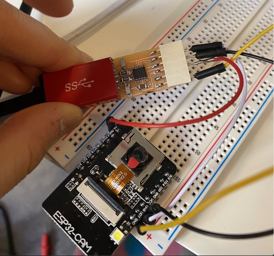
I connected like the photo above, but when I tried to upload the program, I kept getting this error.
A fatal error occurred: Failed to connect to ESP32: Timed out waiting for packet header
I found this trouble shooting guide and it said I needed to connect the VCC of the FTDI to 5V of the ESP32-CAM pin, not the 3.3V one.
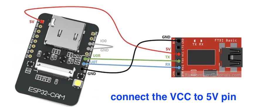
I connected the VCC to 5V instead of 3.3V, and it worked!
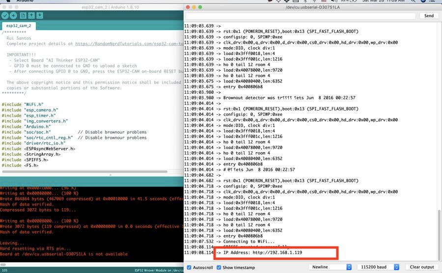
I could see the video streaming coming from the ESP32-CAM on http://192.168.1.119/. You can change the camera settings, such as brightness and frame size from the sketch (camera settings examples).
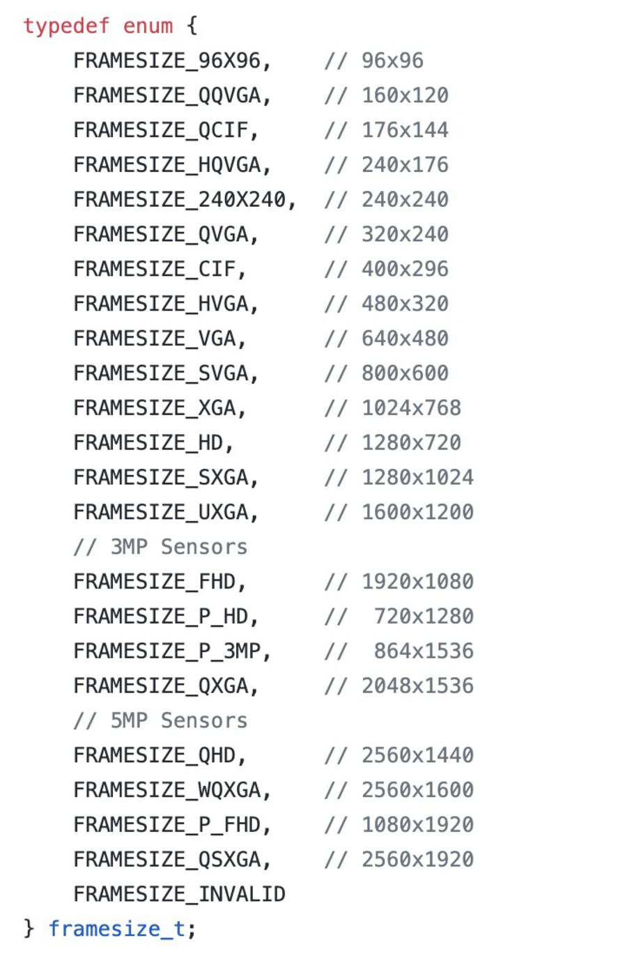
Issue 1. Couldn't change the frame size
But there was one problem. If you see the ESP32-CAM library, there are a lot of options for frame size and I wanted to change the frame size smaller. But for some reason the FRAMESIZE_VGA option was the smallest option that worked. If I set the frame size to the ones that are smaller than FRAMESIZE_VGA, nothing showed up on the server. I still can't figure out the reason.
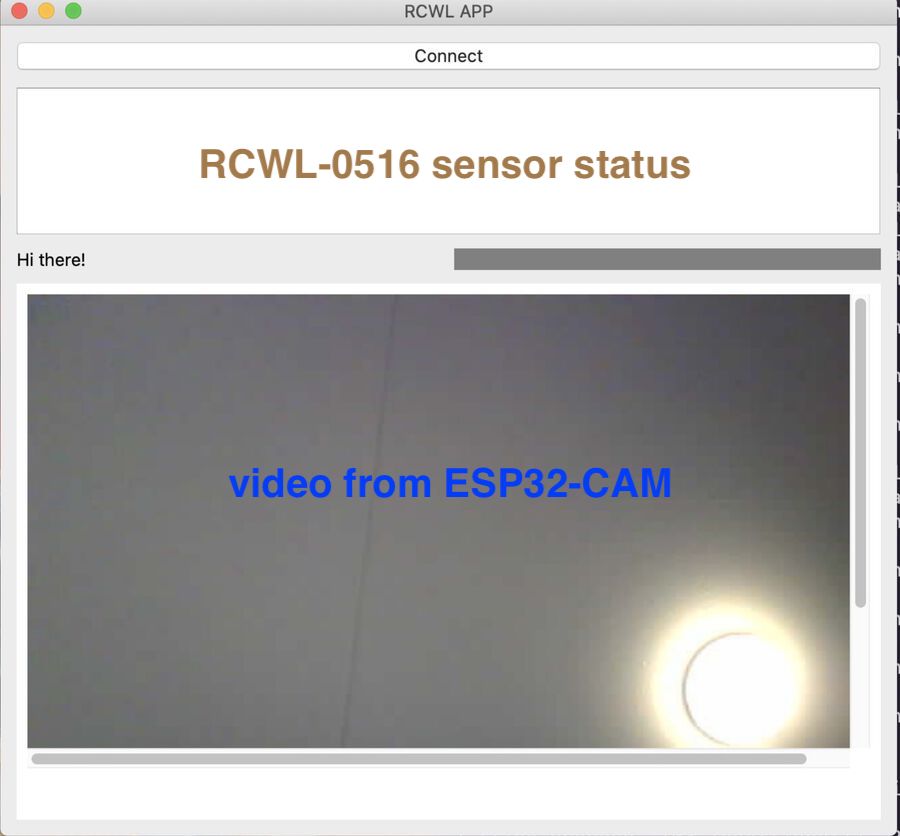
5. Add a camera screen to the PyQt program
Once I made the streaming server running with ESP32-CAM, I added an iframe to the PyQt program (code link). One thing I noticed was if there was any server opened anywhere else, the streaming screen on iframe didn't show anything on it. So I had to make sure that there's no streaming server open on the browser. I don't know why exactly it works this way though.
6. Program ATtiny1614 board with Arduino Uno using UPDI
While I was waiting for the new ATtiny1614 board to be milled, I wanted to test if the ATtiny1614 would work with the RCWL-0516 sensor. I had the ATtiny1614 hello world that I made several weeks ago, so I decided to download the sensor program onto it.
But there was a problem. For some reason, I couldn't download the program on the board through the UPDI. This is the error message I got.
[hyejinahn] ~  % pyupdi.py -d tiny1614 -c  /dev/tty.usbserial-D307S1LG -b 57600 -f /var/folders/81/2y9t06r91nvct4d75yl6smbh0000gn/T/arduino_build_722496/rcwl_sensor.ino.hex -v
INFO:phy Opening /dev/tty.usbserial-D307S1LG at 57600 baud
INFO:phy send : [0x0]
INFO:link STCS to 0x03
INFO:phy send : [0x55, 0xc3, 0x8]
INFO:link STCS to 0x02
INFO:phy send : [0x55, 0xc2, 0x80]
INFO:link LDCS from 0x00
INFO:phy send : [0x55, 0x80]
INFO:phy receive : []
INFO:link UPDI not OK - reinitialisation required
INFO:phy Sending double break
INFO:phy Opening /dev/tty.usbserial-D307S1LG at 57600 baud
INFO:link STCS to 0x03
INFO:phy send : [0x55, 0xc3, 0x8]
INFO:link STCS to 0x02
INFO:phy send : [0x55, 0xc2, 0x80]
INFO:link LDCS from 0x00
INFO:phy send : [0x55, 0x80]
INFO:phy receive : []
INFO:link UPDI not OK - reinitialisation required
Traceback (most recent call last):
  File "/usr/local/bin/pyupdi.py", line 178, in  <module>
    _main()
  File "/usr/local/bin/pyupdi.py", line 95, in _main
    device=Device(args.device))
  File "/usr/local/lib/python3.7/site-packages/updi/nvm.py", line 17, in __init__
    self.application = UpdiApplication(comport, baud, device)
  File "/usr/local/lib/python3.7/site-packages/updi/application.py", line 17, in __init__
    self.datalink = UpdiDatalink(comport, baud)
  File "/usr/local/lib/python3.7/site-packages/updi/link.py", line 31, in __init__
    raise Exception("UPDI initialisation failed")
Exception: UPDI initialisation failed
INFO:phy Closing /dev/tty.usbserial-D307S1LG
The problem must have been either the ATtiny1614 board or the UPDI. I checked the board with a multimeter and re-soldered some parts again, but it still didn't work. Fortunately, I had another ATtiny hello world board, and I decided to program it with the Arduino board. I watched this video tutorial to learn how to do this and it helped me a lot. I used jtag2updi to program my board with the Arduino board.
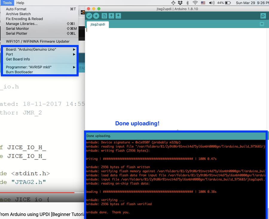
How to program an ATtiny with an Arduino board
First, make sure if you have the megatinycore library installed on the Arduino IDE
Download jtag2updi and open it
Open the jtag2updi.ino file to the Arduino IDE. The main file is empty but it's ok because all the files are spread across.
Connect your Arduino board to your computer
Then, upload it to the board like a typical Arduino sketch
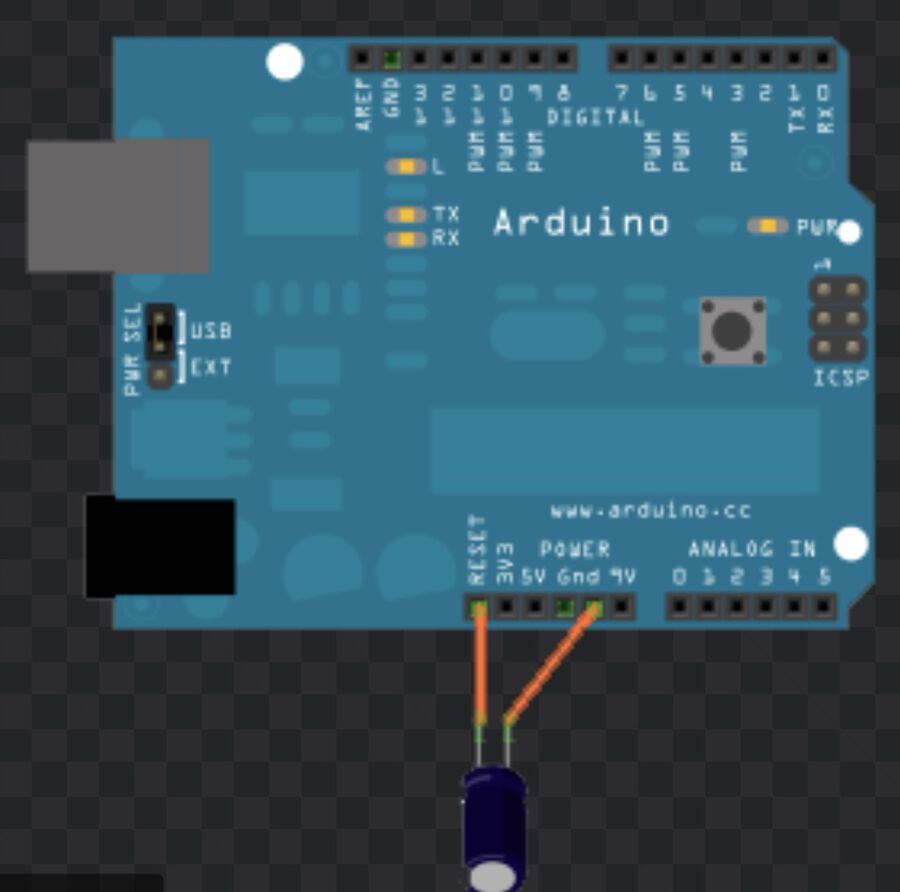
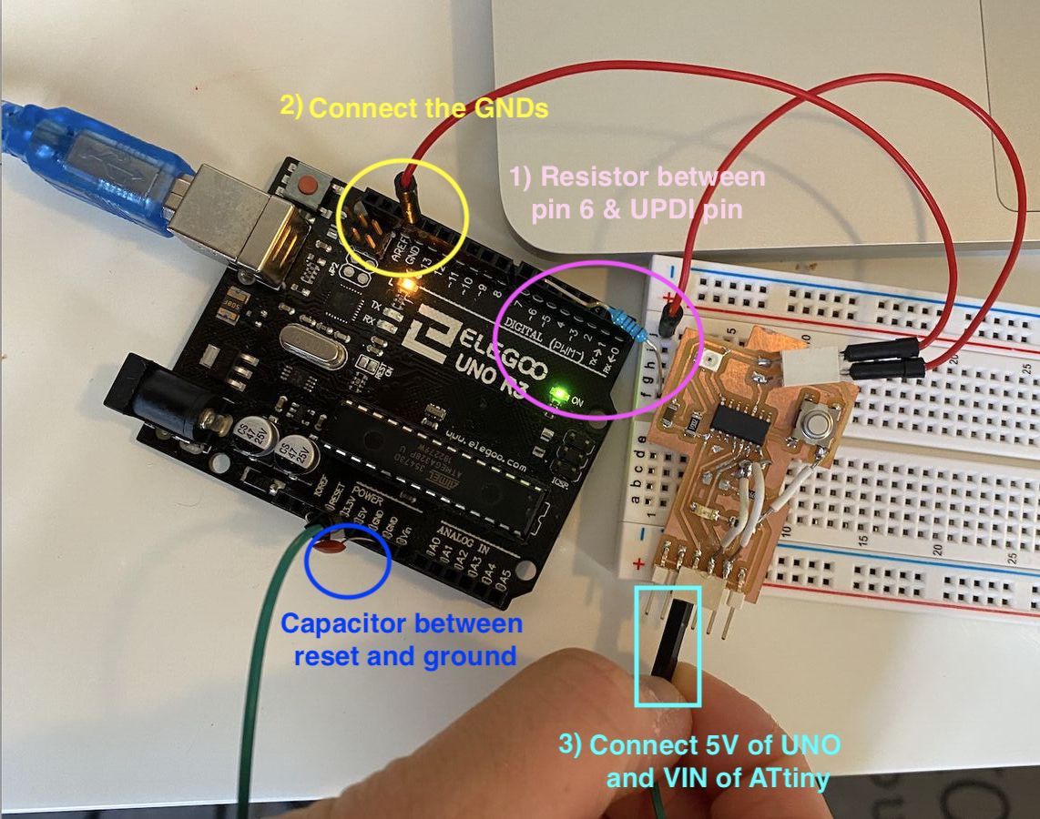
Once it's downloaded to your board, you need to disable the reset that is triggered every time you upload a sketch. That would cause the code to overwrite the program of flash instead of the ATtiny. The simplest way is to add a 10 micro F capacitor between reset and ground.
Then, you only need 3 pins to connect between the UNO board and the ATtiny. The first one is the UPDI data pin. It is configured to be pin 6 and it needs to be connected to the UPDI pin of ATtiny. You have to add a 4.7K resistor between them. I only had a 5K one and it worked fine. The second one is connecting the grounds of each board. Lastly, you have to connect the 5V of the UNO to the VIN of the ATtiny.
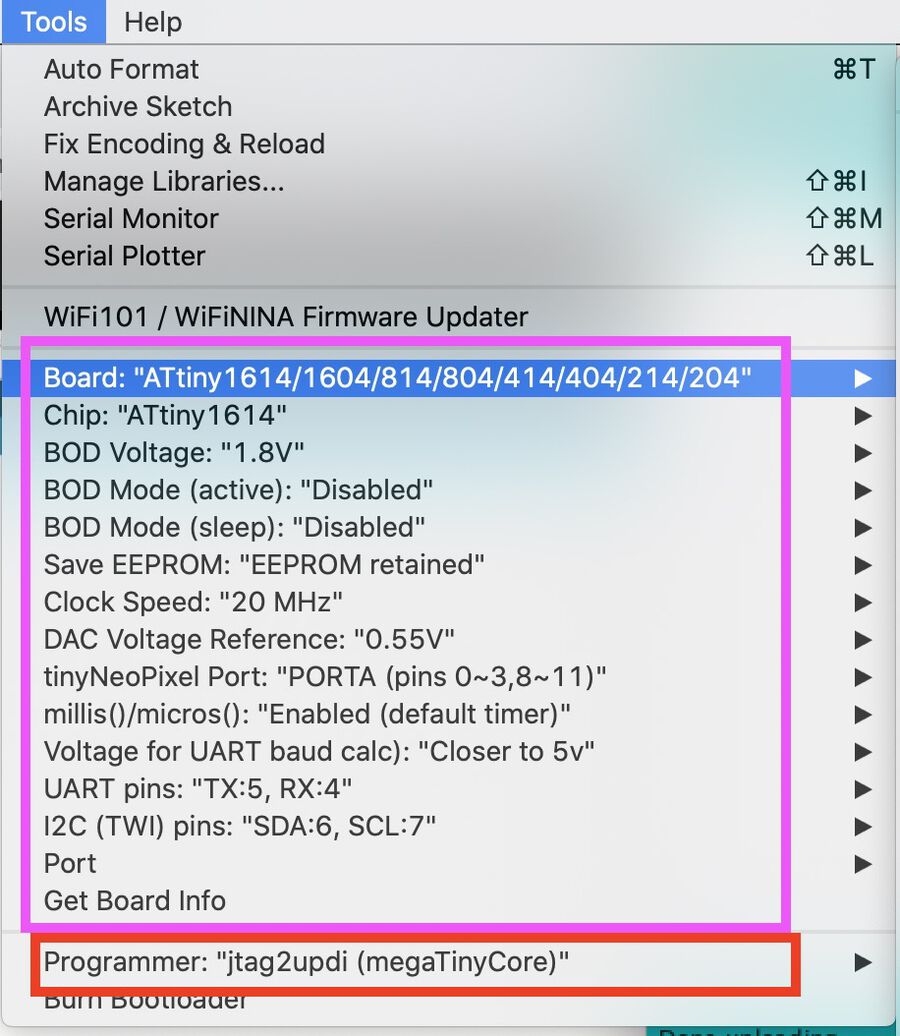
Ready the code that you want to upload to the ATtiny, and change the settings. I selected the ATtiny1614 board and set the rest of the settings as they were except for the Programmer. Change Programmer to jtag2updi(megatinyCore) and then you're good to go
git clone https://github.com/SpenceKonde/jtag2updi.git
I spent so much time making it work because the ATtiny I used was a little bit jenky. There were some wires coming off from the lead on the board and it caused some issues. I needed to check if there were any other loose parts. The code I uploaded to the ATtiny1614 board was the same as the RCWL-0516 code.
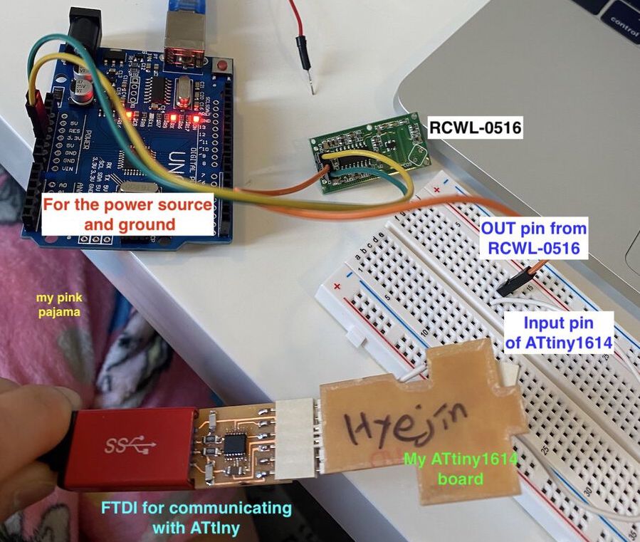
Temporary setup for testing the ATtiny1614 board
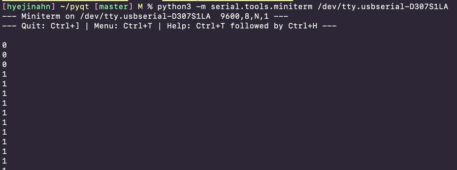
YAY! I was able to read the RCWL-0561 sensor data from the ATtiny1614 board through the miniterm program and even on the PyQT program I made. The temporary setup was a nightmare to work on, but it worked well. :D
7. Make a new ATtiny1614 board
After finishing soldering the new board, I downloaded the code onto it.
Then, I set up the ESP32-CAM module powered with the Arduino board next to the new board.
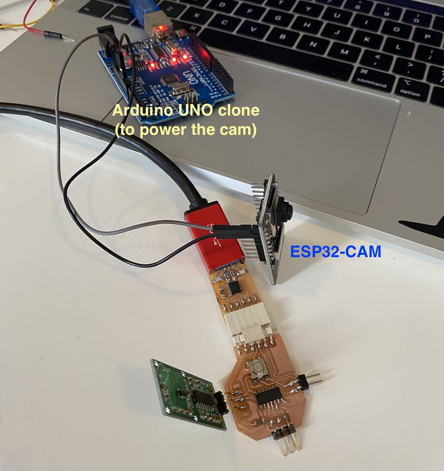
The video below is the screen recording of the setup above and the PyQt program. The ESP32-CAM shows the live video while the RCWL-0516 sensor collects the movement data.
If I move my hand towards the RCWL-0516 sensor, it prints 1 and changes the square color to red. And if I let my hand stay still, it prints 0 and changes the square color back to grey. It works like a charm! :D
Group assignment
I couldn't join the group assignment this week because I was feeling unwell. But the other students did very well with the ultrasonic sonar distance sensor. (Group assignment documentation)