Computer-Controlled Machining
ASSIGNMENT
Individual Assignemnt
Make Something big
Group assignment
Test runout, alignment, speeds, feeds, and toolpaths for your machine
Individual Assignement
WORK FLOW
Idea
For my weekly assignment I wanted to design an object that had a specific purpose, that was something useful but at the same time not something obvious.
So I decided to make a table but using different techniques: milling, 3D printing, using and colouring and casting epoxy resin.milling, 3D printing, using and colouring and casting epoxy resin.
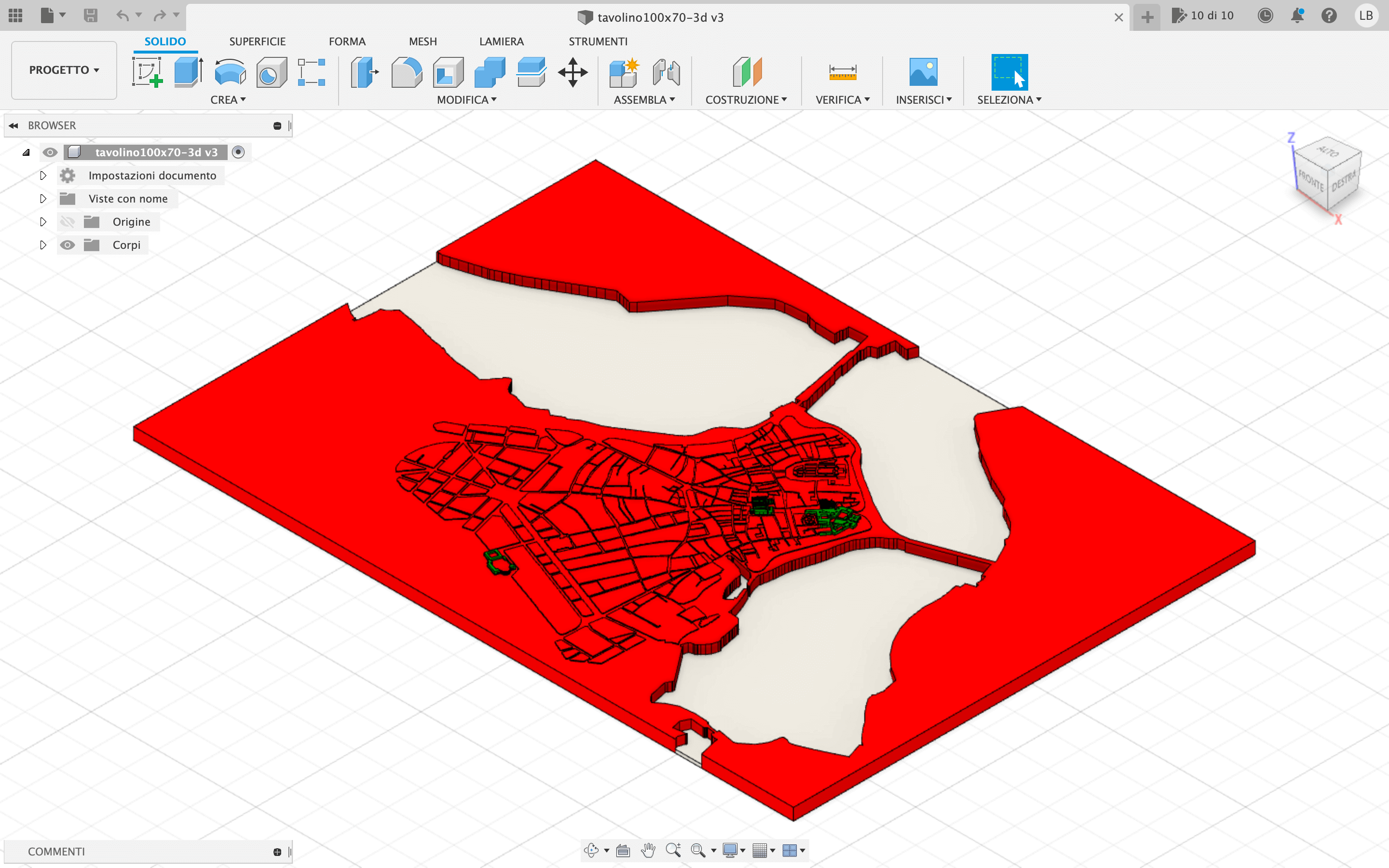
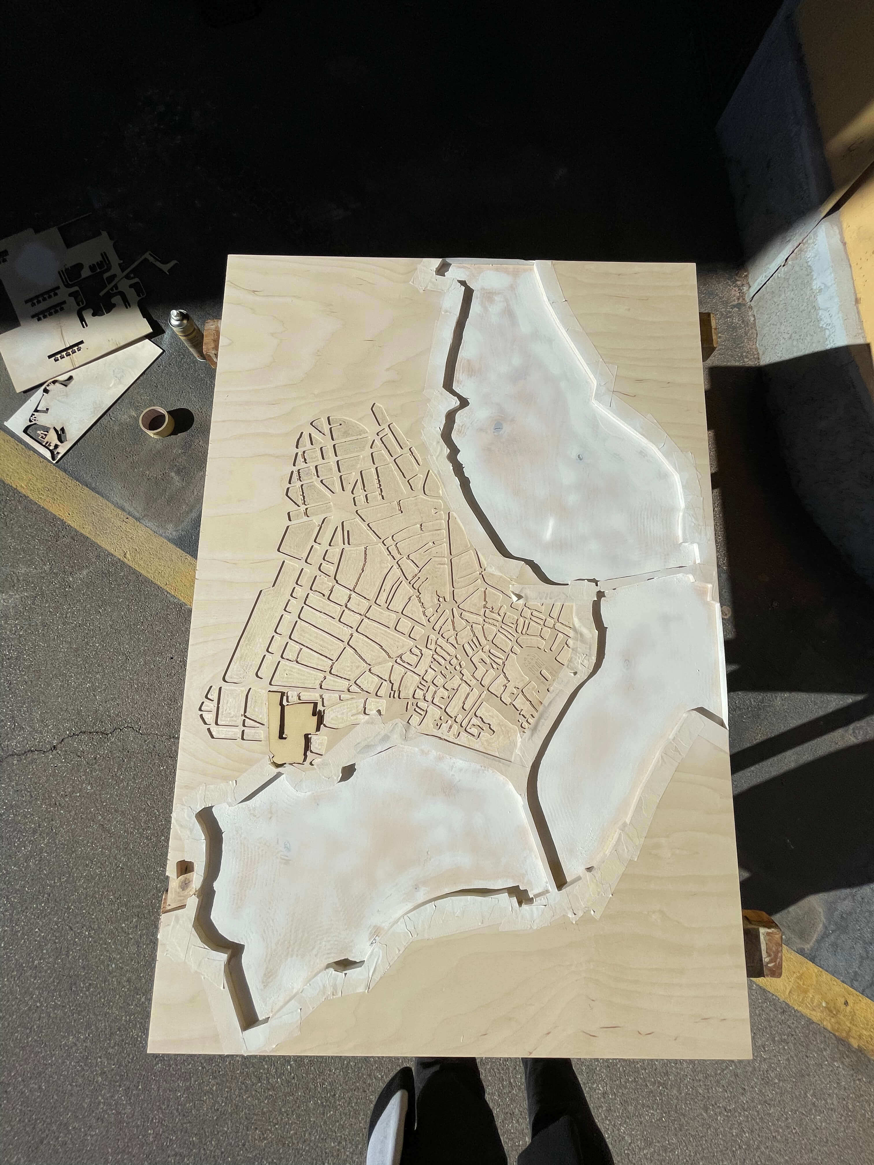
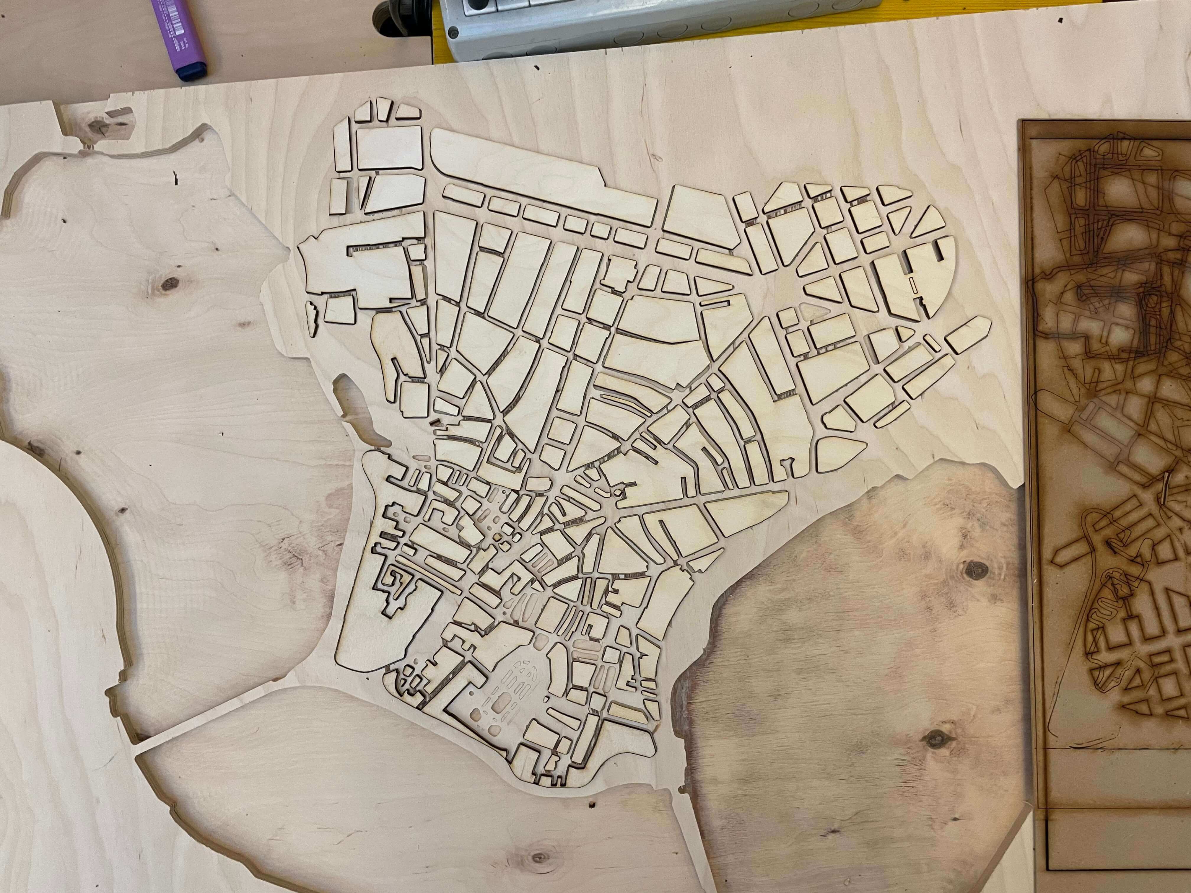
To make it different from any other table, I decided to mill the map of Mantua, my city, leaving out the most important buildings (Basilica di S.Andrea, Duomo, etc ...) because I'm going to print them with a 3D printer.
First of all I decided on the dimensions and the various heights.
After deciding the dimensions of my table I went looking for the wooden top that could contain my table without any problem, with the right height and the right type of wood.
After deciding the right size I used Autodesk Fusion 360 to draw the map of Mantova (obviously the map is stylized).
Once the drawing was finished I projected and then exported the file in DXF format and then went to work with V-Carv for the "cutting sections" and their heights.
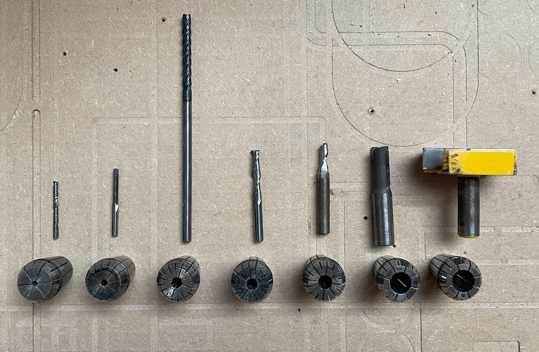
For this project I will have to use 2 different drills: a smaller one for milling the plan and a larger one for removing material from the plan, milling the lakes, and cutting.
During the milling of the table I will have to change the tip of the cutter, because there are smaller and larger milling parts.
So the steps are as follows:
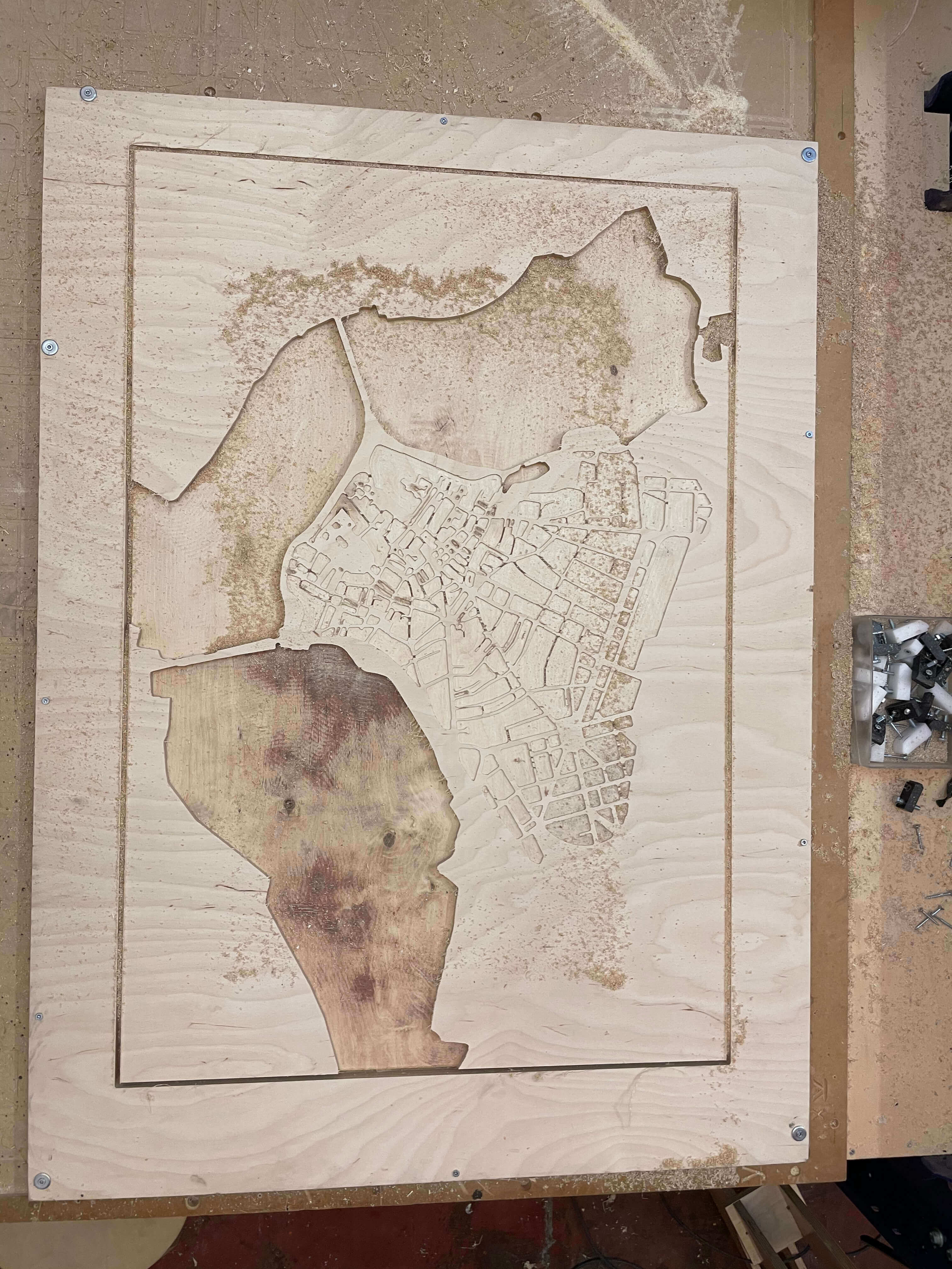
- Mill the lakes with a 6mm drill bit;
- Mill the floor plan in order to remove material with a 5mm offset with a 6mm drill bit;
- Mill the plan precisely with a 3.75mm drill bit.
- Cutting the plan with the 6mm drill bit;
Once the files are finished, I export them in the cutter readable SBP format.
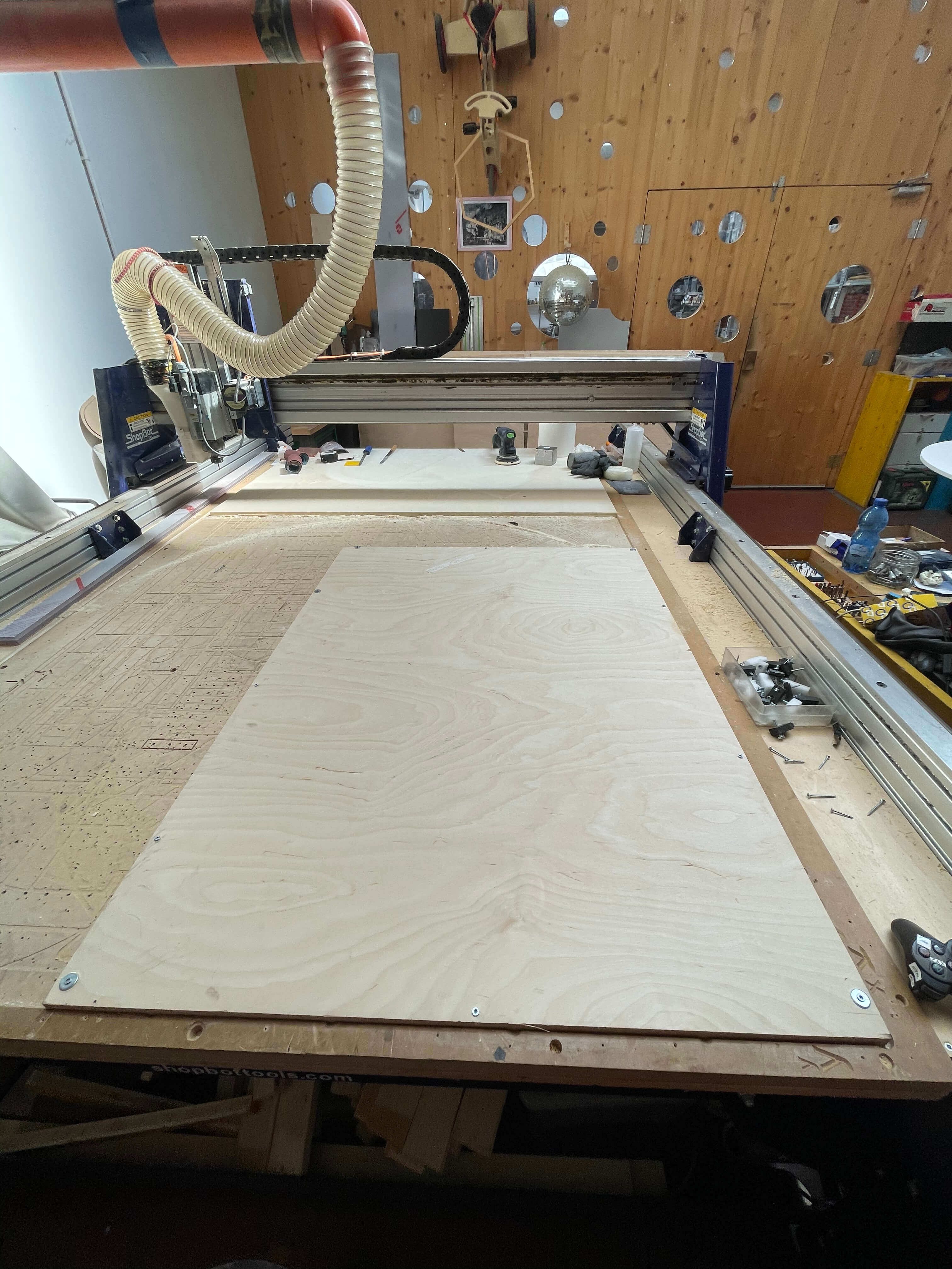
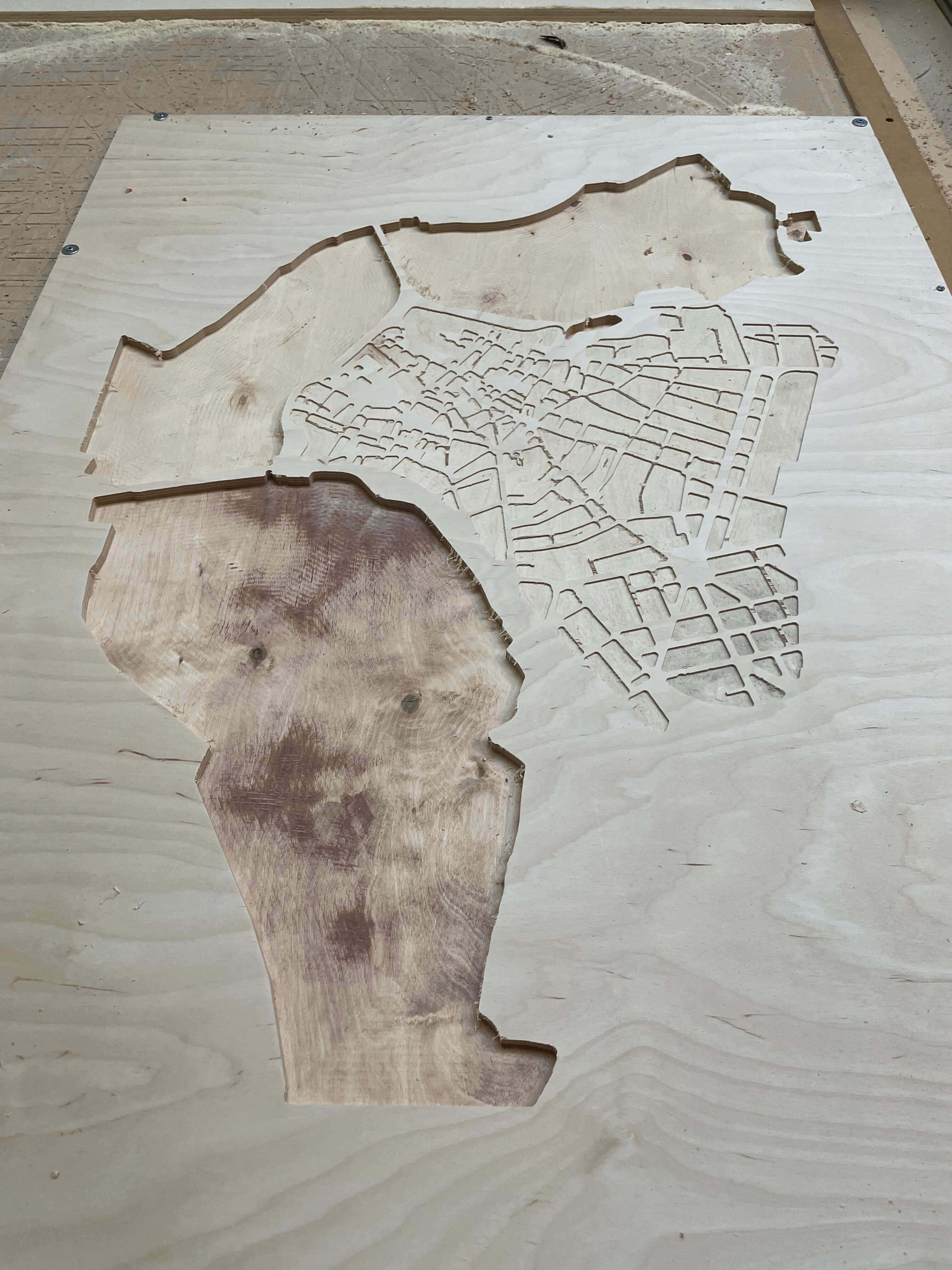
Once the file is ready I go to the milling cutter with my wooden panel which I will fix with screws so that it remains stationary during milling.
- I fix my panel with 10 screws;
- I insert my files and copy them onto the PC dedicated to the milling machine;
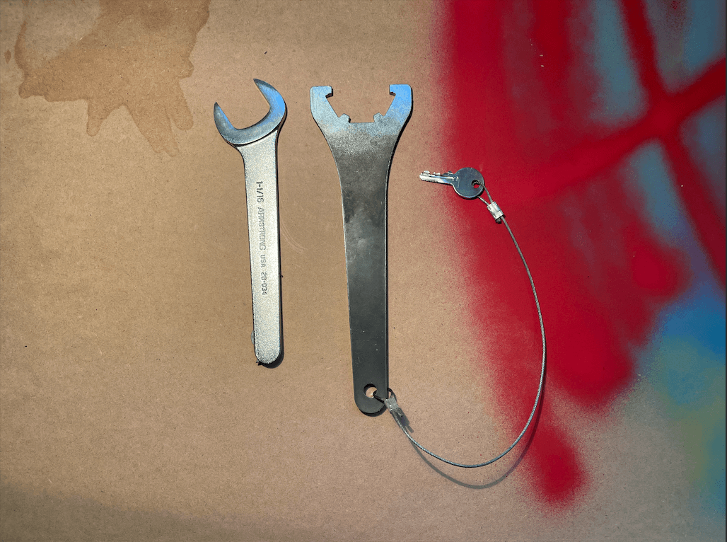
- I insert the appropriate drill for the first milling;
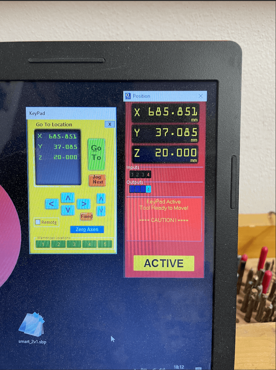
- I set the "x-y-z" axes as I had set on the V-Carv file;
- I start the milling cutter and wait for it to finish.
GROUP ASSIGNMENT
HOW TO SET UP SHOPBOT ?
First of all we copy our files to the Desktop or to a folder we have on our computer.
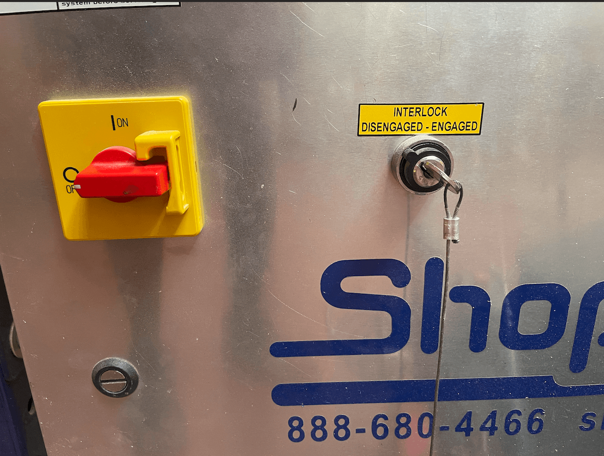
After that, we have to do some basic steps to turn it on and then mill:
2.
3.
4.
5.
6.
7.
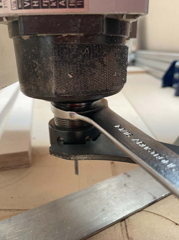
BUT HOW DOES THE ZEROING OF THE "Z" AXIS WORK ?
On the GANTRY there is a "metal bar" electronically connected to a sensor so when the drill touches the metal bar on the cutter (or stock) table there is a short circuit and the ShoBot machine realises that it has arrived at its destination, so it calculates how far it has fallen by adding the thickness of the metal bar. This action is repeated twice, once at a very high speed and once at a higher speed.
...After clicking on the "Z axis" icon...
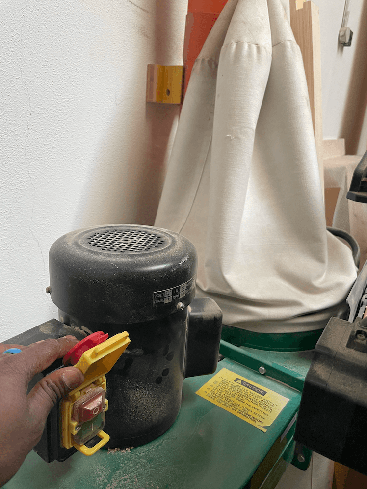
8. Once all the settings have been made, the last thing we need to do before starting to cut is to start up the vacuum cleaner so that we don't risk ruining our work but have a clean cut as possible. To switch it on, just press the green button next to the vacuum cleaner bag.
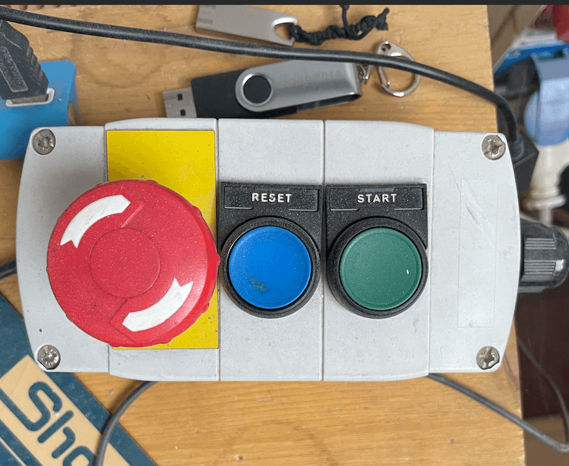
9. Having set the X-Y-Z axes and switched on the vacuum cleaner, all we need to do now is to start our milling machine. Just click on "CUT FILE" on our computer screen to switch on the machine and then press START to make the spindle start turning.
|
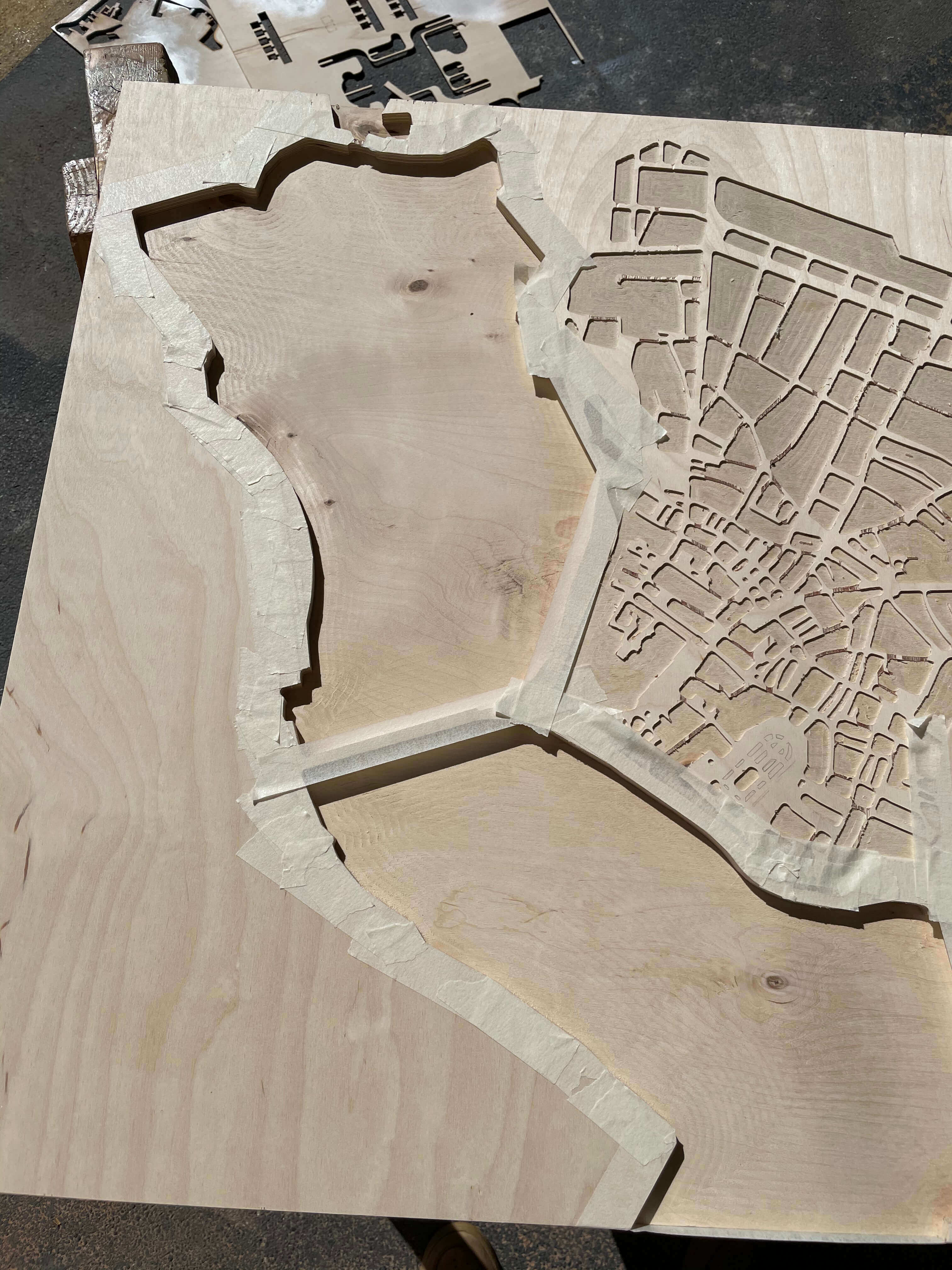
|
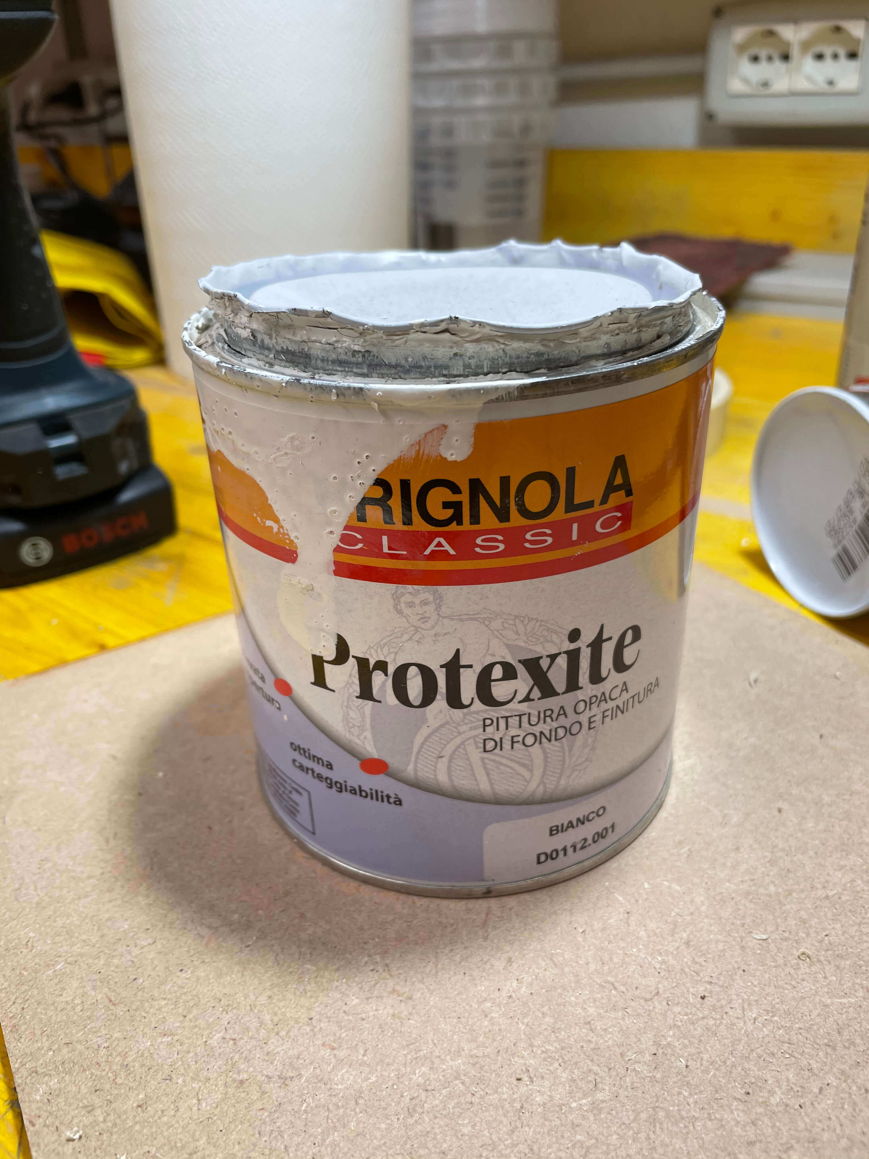
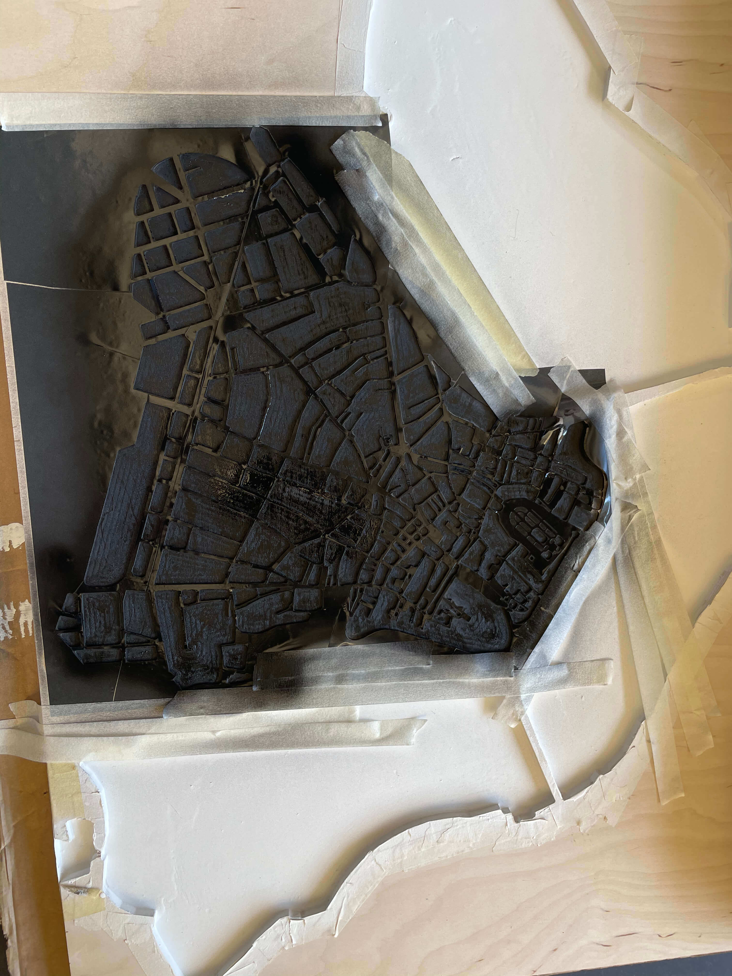
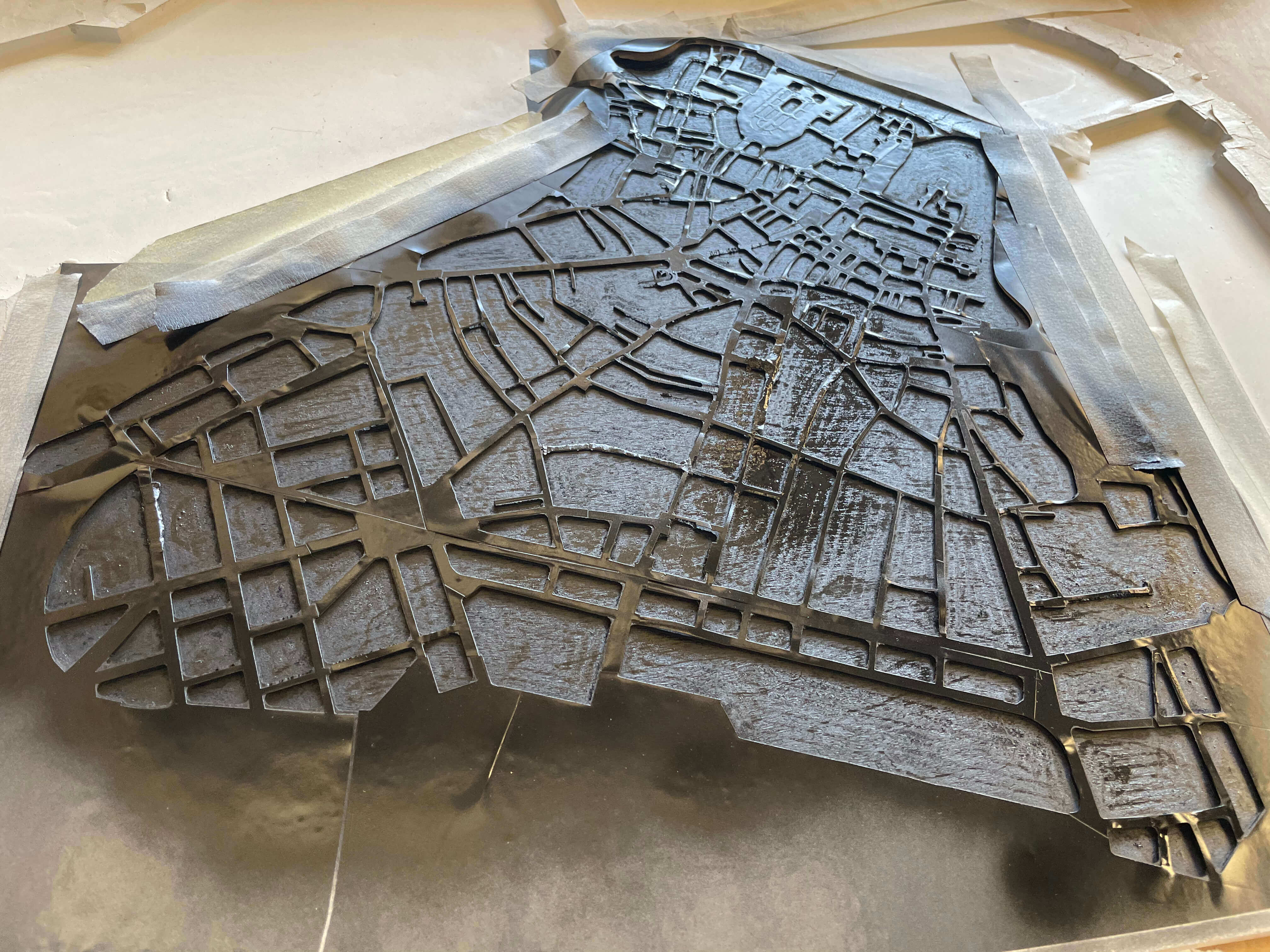
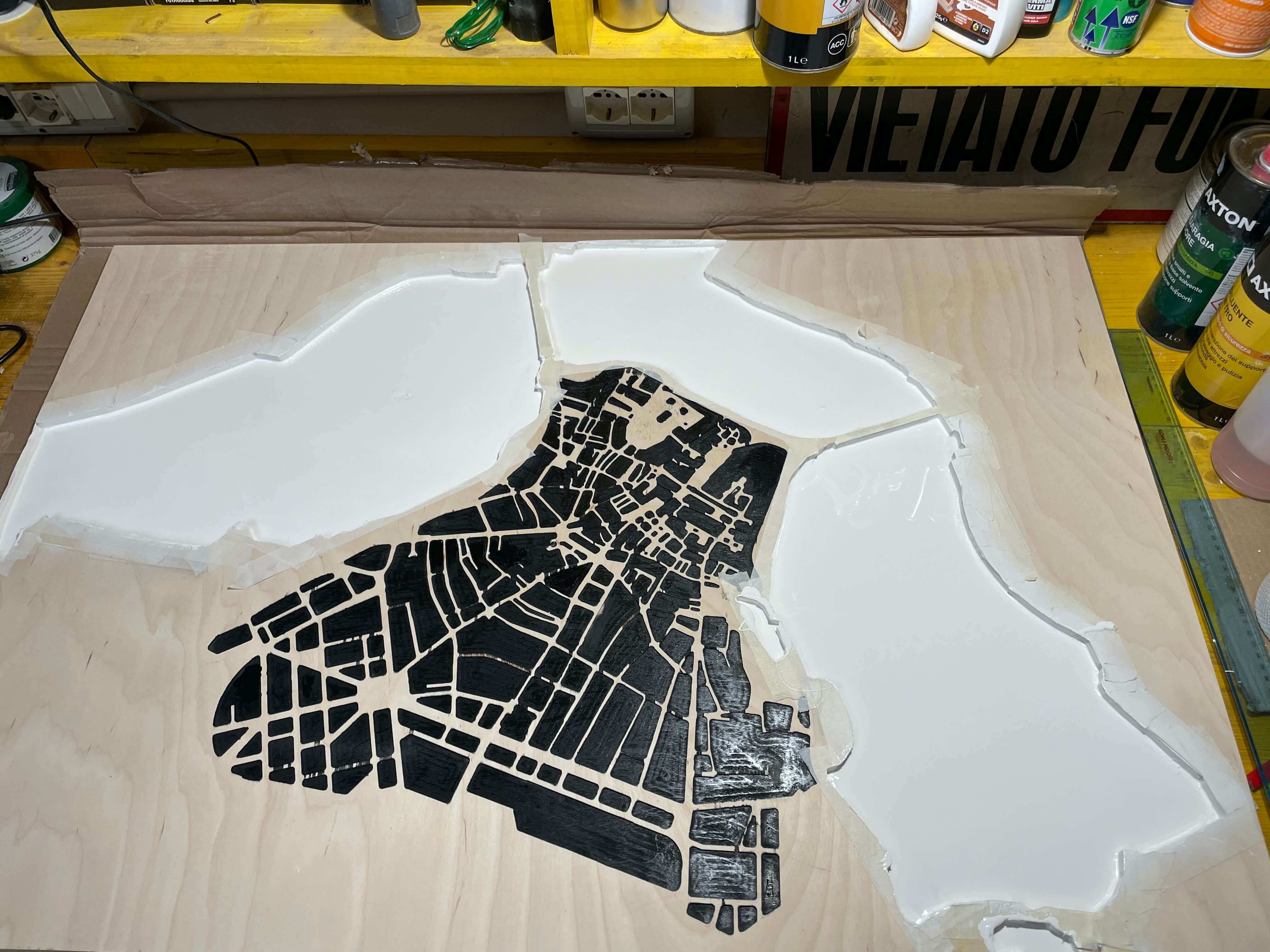
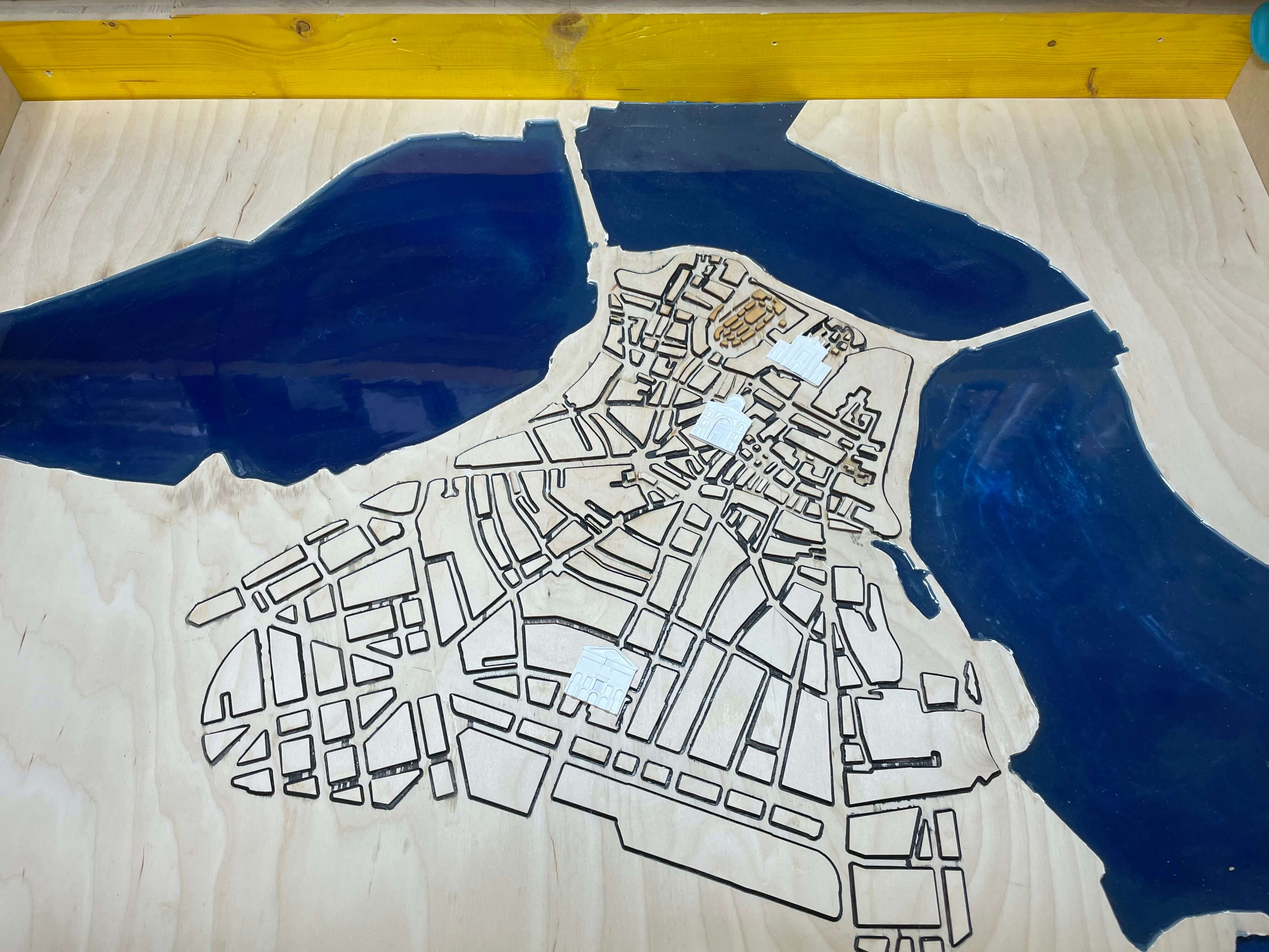
Now that my table has been milled and cut, I pass it with the orbital to remove excess material. After that I put it on two stands and start to scuff it (with paper tape) on the perimeter and on the perimeter of the lakes. This is because I'm going to give a coat of white paint as a base for the lakes which I will then fill with blue epoxy
|
|
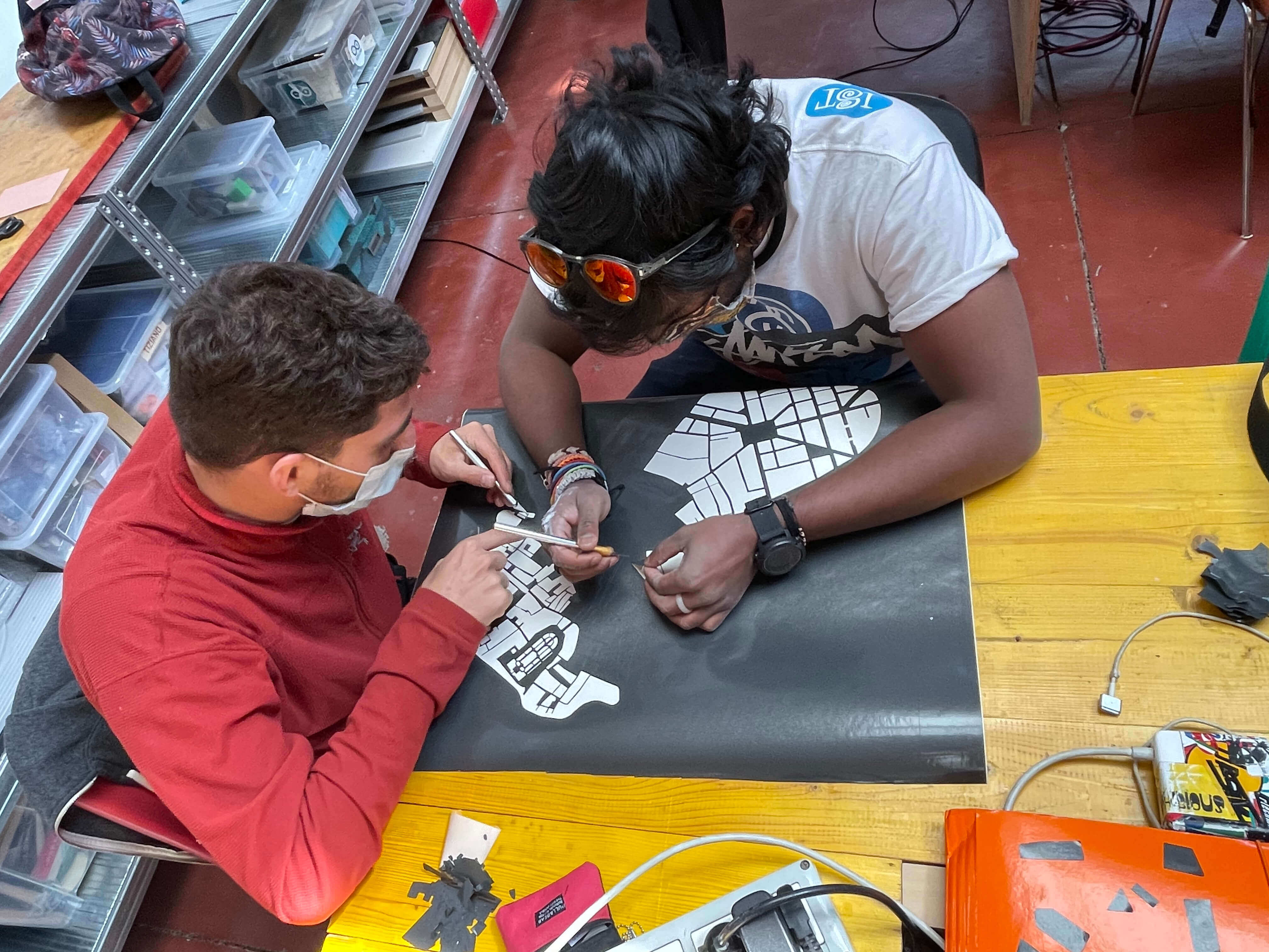
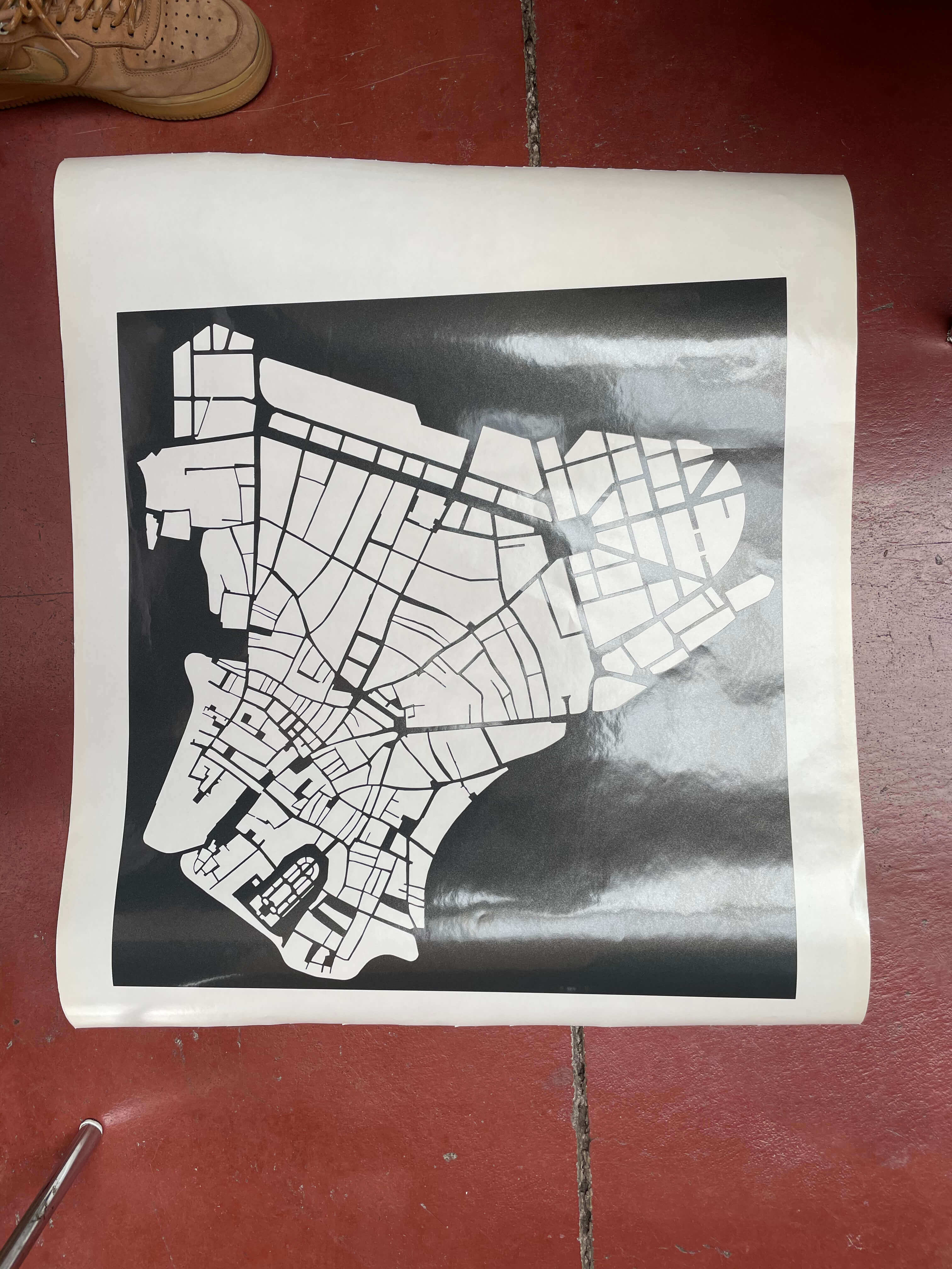
While I wait for the first casting to dry I prepare a stencil with the Vinyl Cutter where I will reproduce my seedling.
How to use the Vinyl Cutter ? Let's go and have a look to (WEEK_3)
The reason why I am making this stencil is because I will also have to paint the inside of my seedling with black paint, so that the pieces that I am going to laser will stand out more.
|
|
|
|
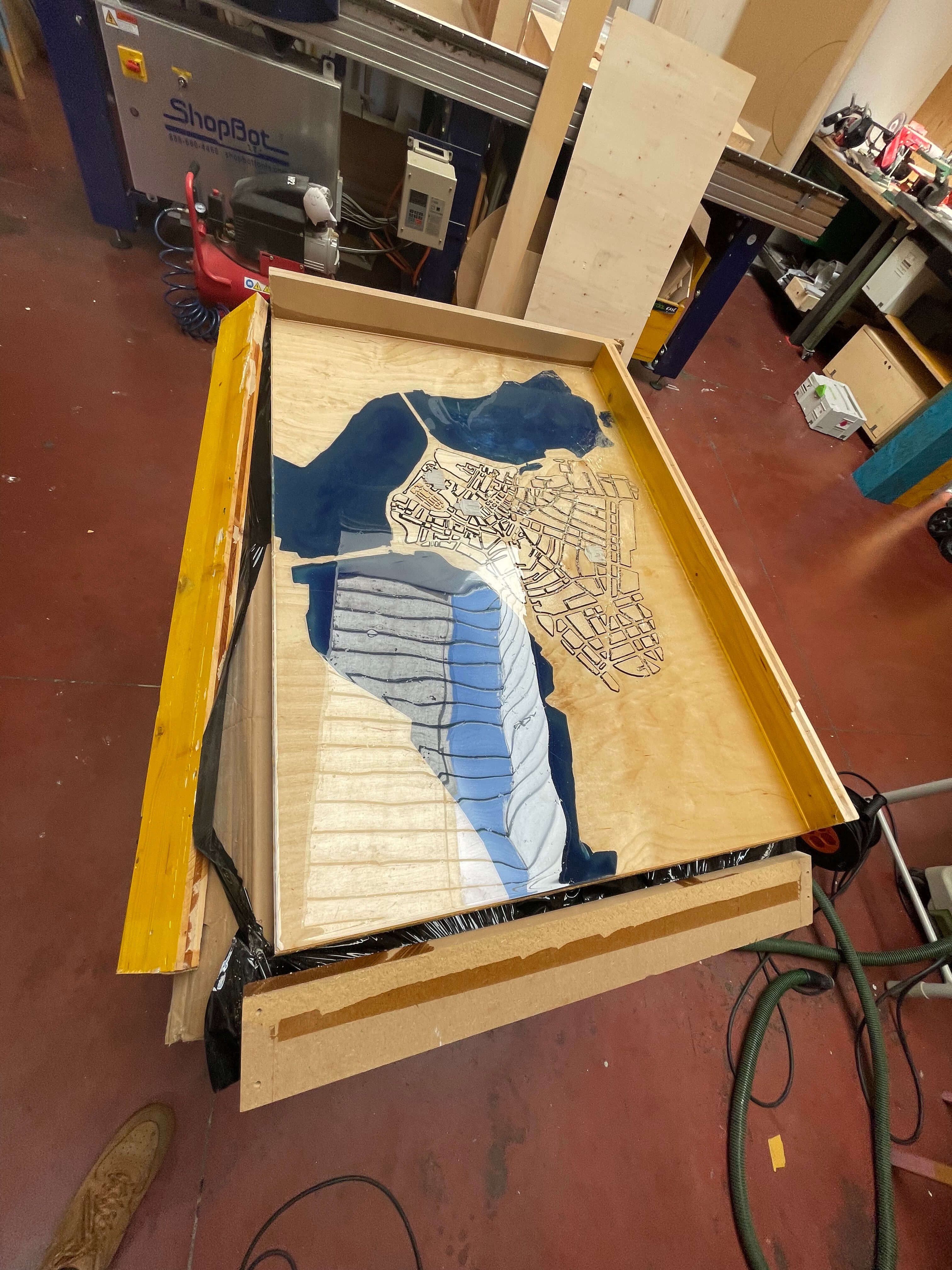
Once the paint (both white for the lakes and black for the floor plan) has dried, I can go and mix the epoxy resin component A with the epoxy resin component B.
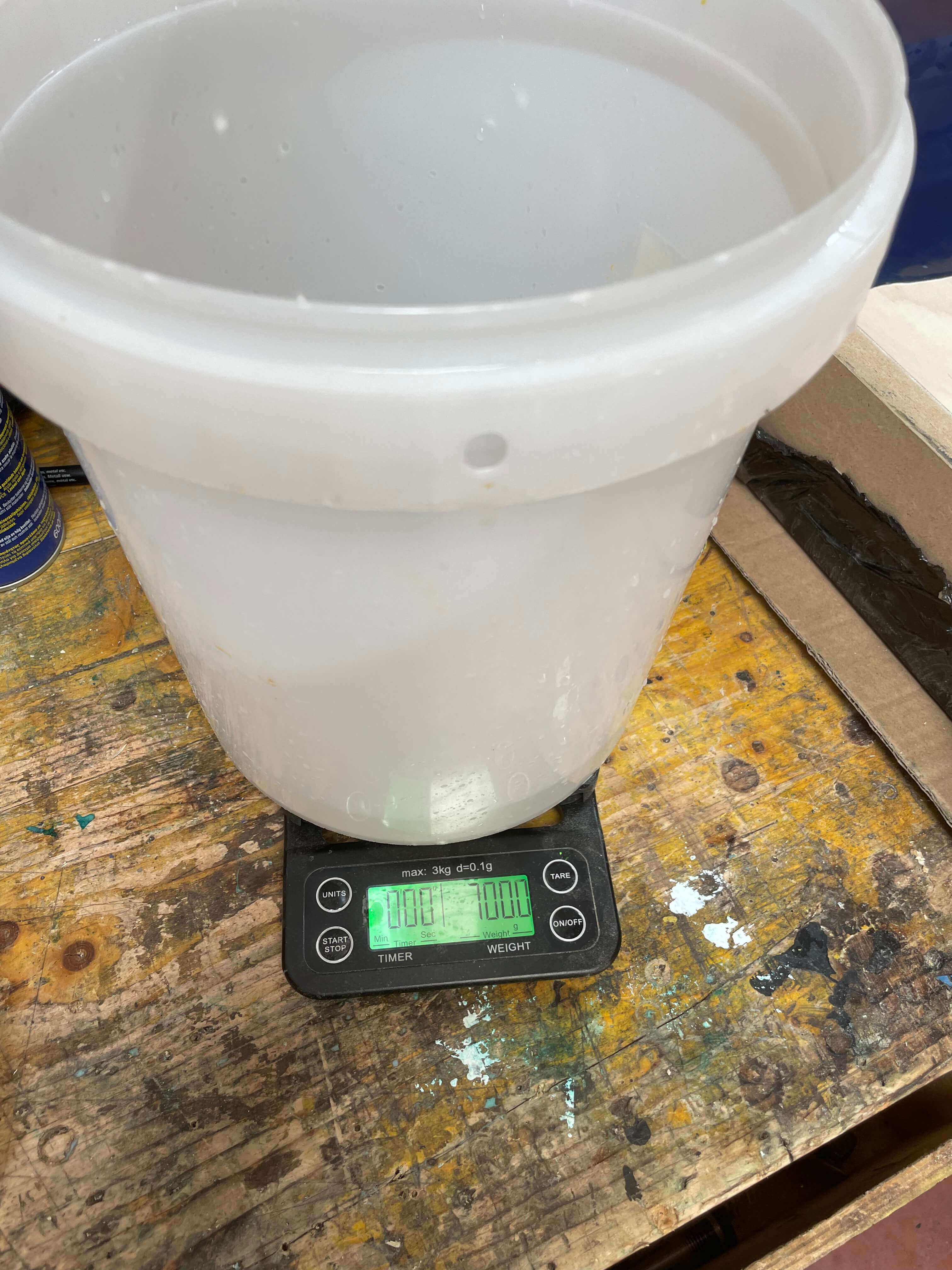
How do I calculate how much component B I have to put in?
Measure the amount of component A in grams and multiply the figure by 0.66, from which we will know the grams of component B that we will need to mix everything correctly.
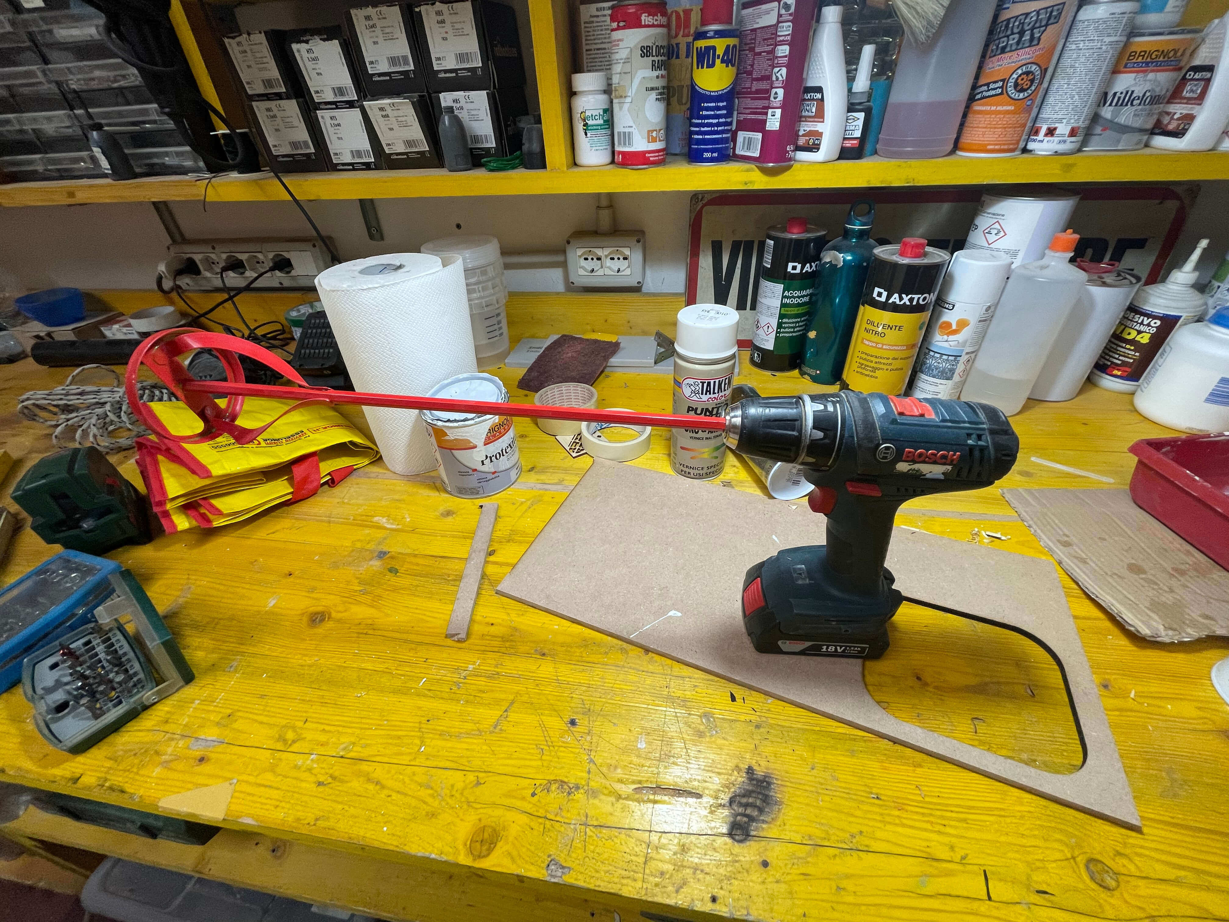
After the resin has been put in the correct doses of epoxy resin A and epoxy resin B I go to mix the resin with dyes to give the colour to my lakes and to get the dark blue I wanted to obtain, considering the base of white I had put on the wood, I used the dyes: electric blue, petrol green, white and black.
I continue to mix by means of the special "tip" attached to the drill and in the meantime I put a little bit of colour waiting for it to be mixed well so as to see the result before adding more or another colour.
|
|
Once the paint (both white for the lakes and black for the floor plan) has dried, I can go and mix the epoxy resin component A with the epoxy resin component B.
How do I calculate how much component B I have to put in? Measure the amount of component A in grams and multiply the figure by 0.66, from which we will know the grams of component B that we will need to mix everything correctly.
After the resin has been put in the correct doses of epoxy resin A and epoxy resin B I go to mix the resin with dyes to give the colour to my lakes and to get the dark blue I wanted to obtain, considering the base of white I had put on the wood, I used the dyes:
electric blue, petrol green, white and black.
I continue to mix by means of the special "tip" attached to the drill and in the meantime I put a little bit of colour waiting for it to be mixed well so as to see the result before adding more or another colour.
While waiting for the resin to dry I check that the black paint has dried everywhere without any problems or gaps. Since it has dried everywhere I use the orbital with a thin paper to remove black machines. After that I clean the top and vacuum the dust, because now that the resin has hardened I can glue the pieces of my plan
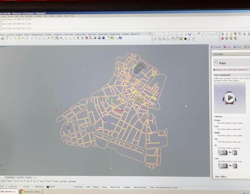
How do I get the parts from my plan ? Using the same file that I used for milling, I just export the plan in DXF format.
Then, using Rhino, I make a 2mm OFFSET with ROUNDED EDGES.
What is an OFFSET ?
Offsetting allows me to reduce the size of my figures but on the perimeter, so for example, if I have a square as a figure and I offset it by 2mm, all 4 sides will be reduced by 2mm towards the centre without the shape being modified.
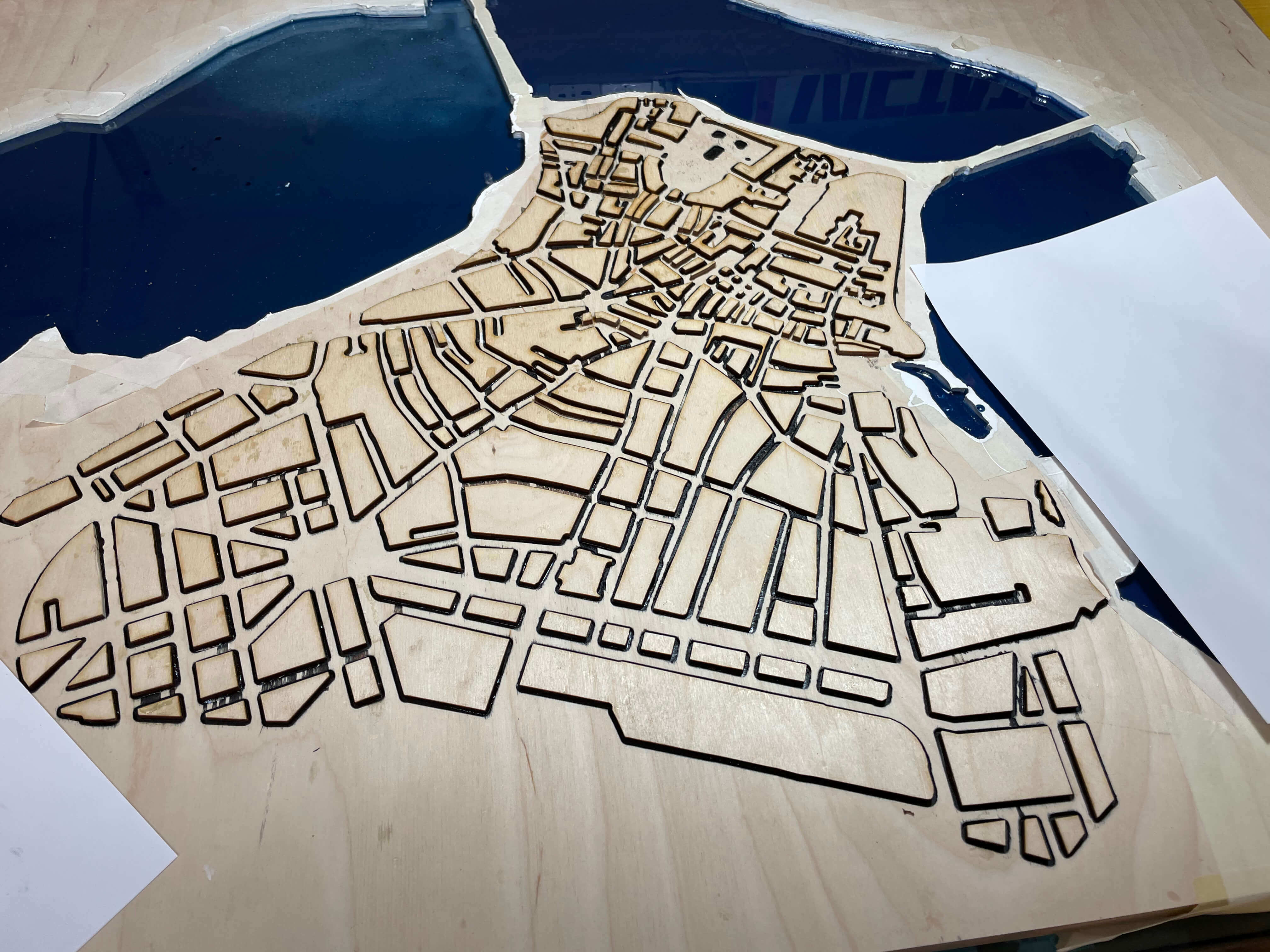
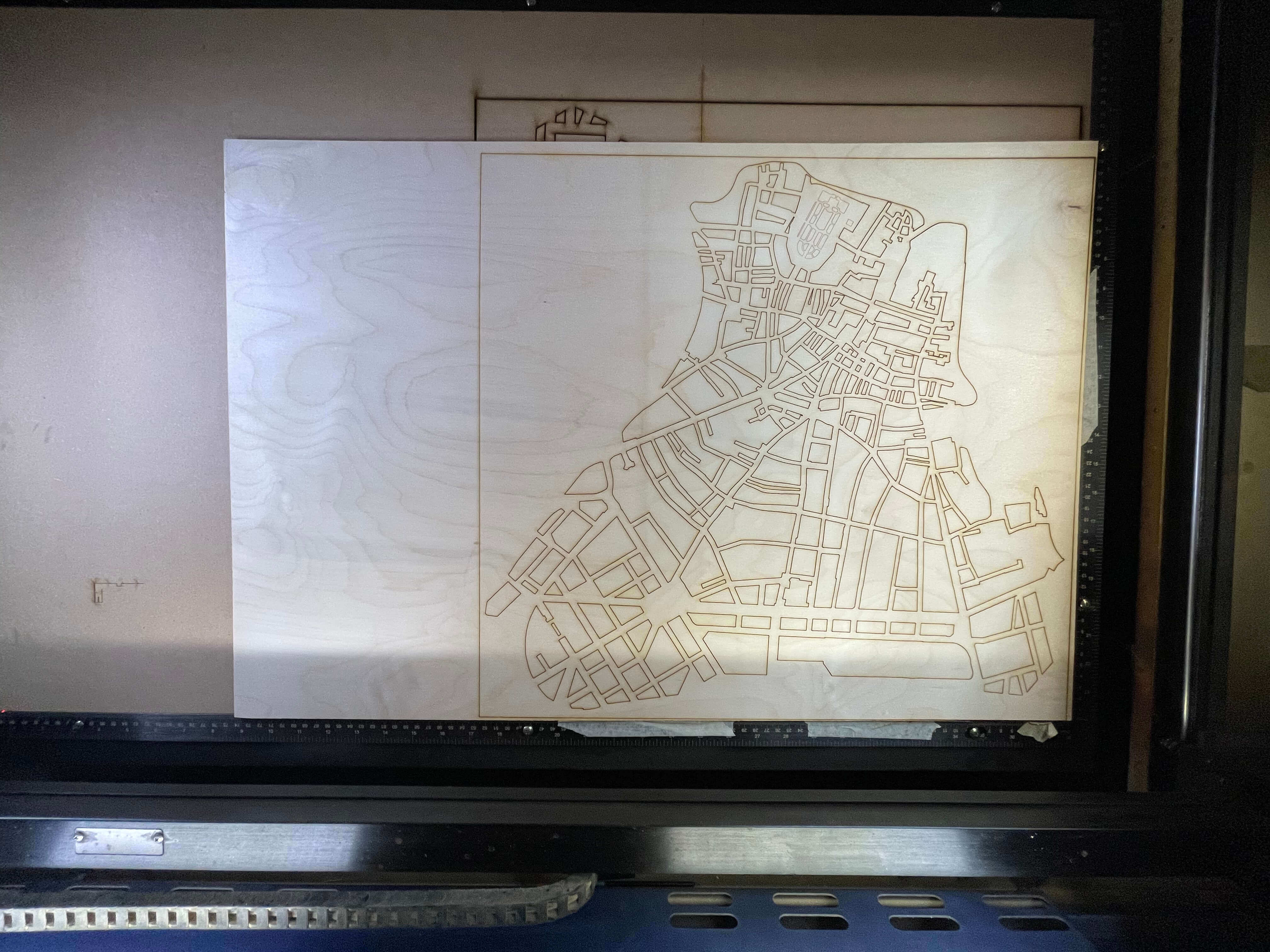
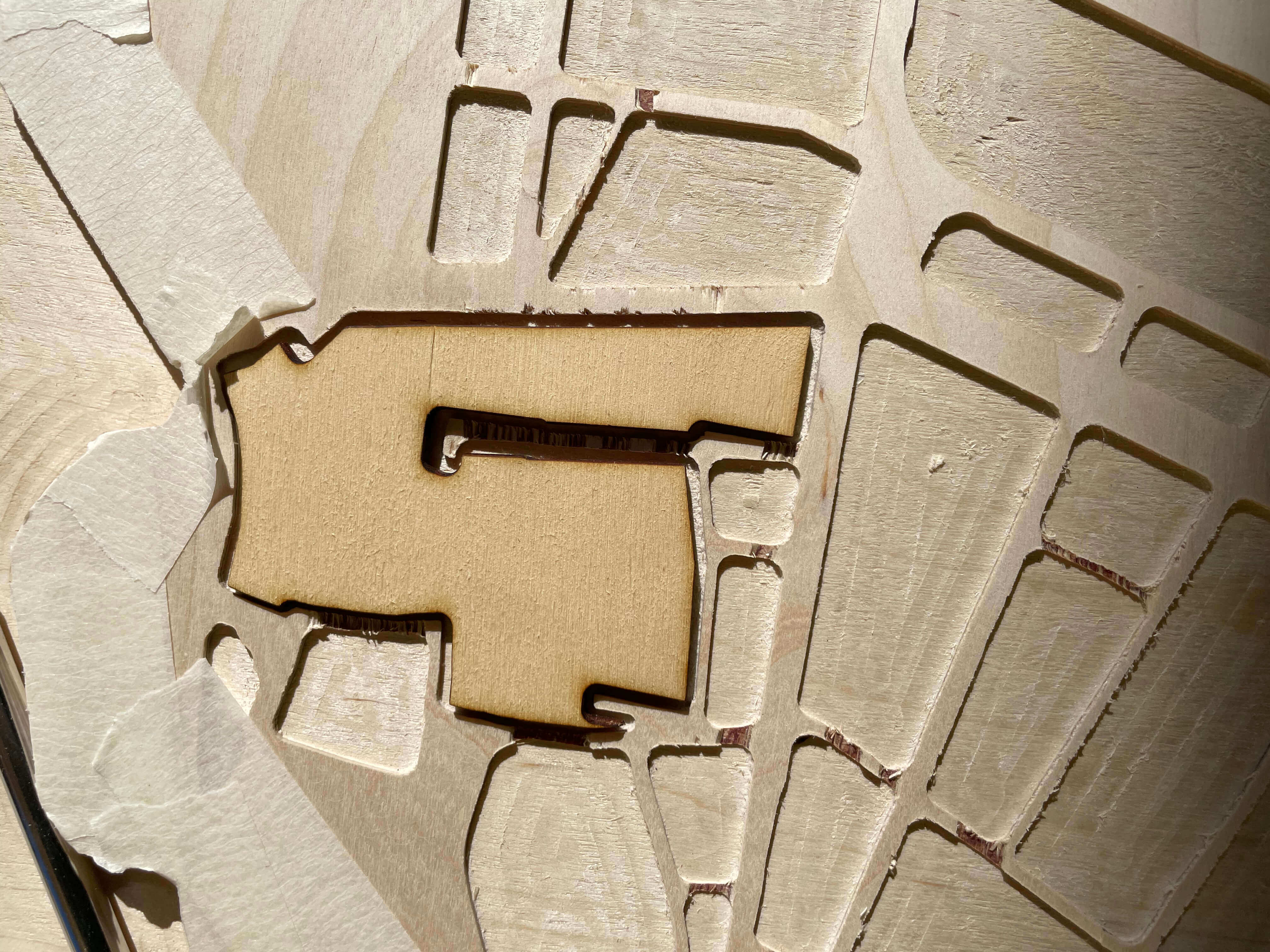
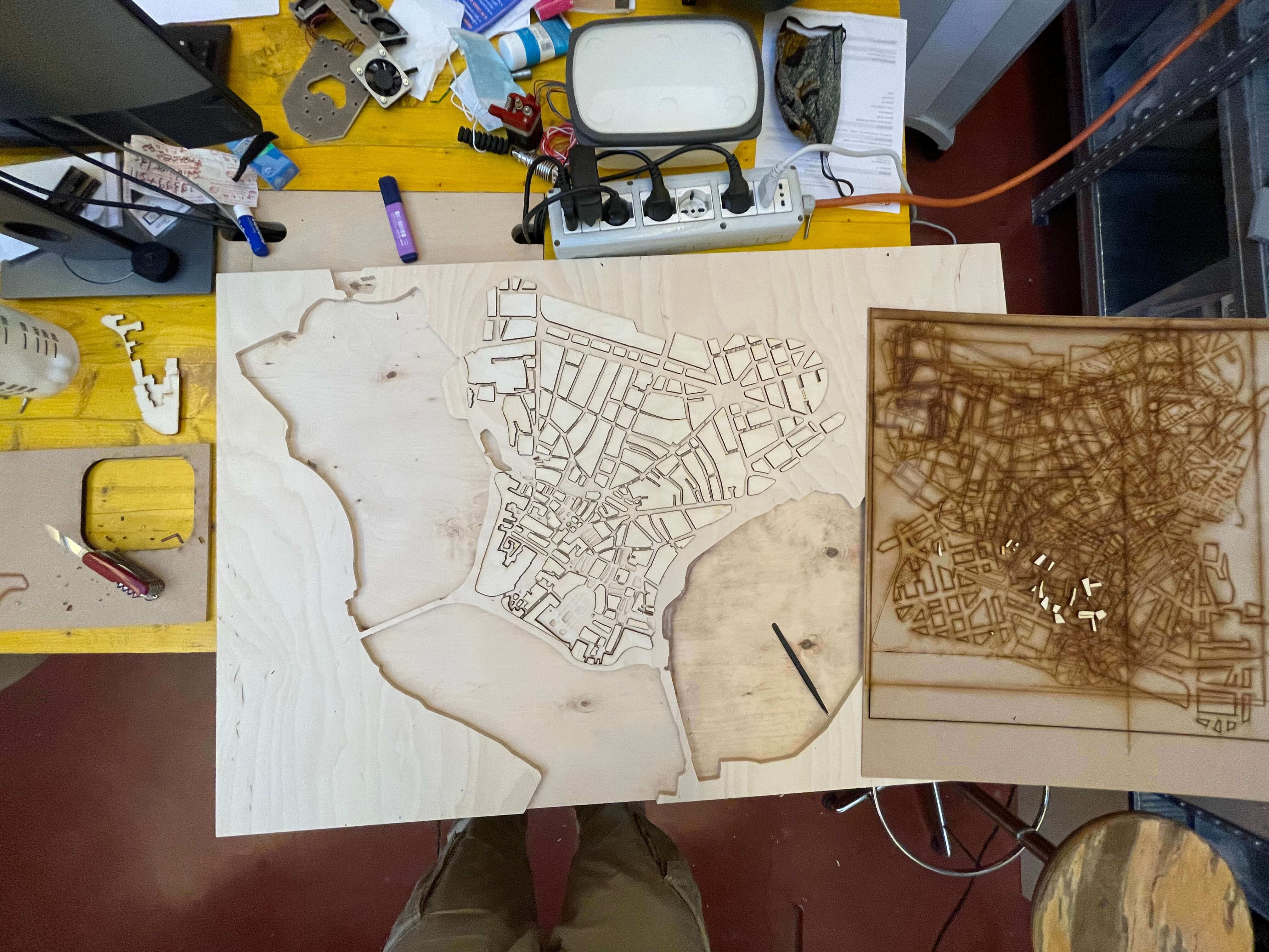
Now I'm ready to laser the plan and I'm using 4mm wood but I'll keep a wood or FDM underneath as a base so that when the laser cuts my plan, the smaller pieces won't fall underneath but will remain on the plane and making it easier for me to "geometry" the plan and better understand where to place them.
|
|
|
|
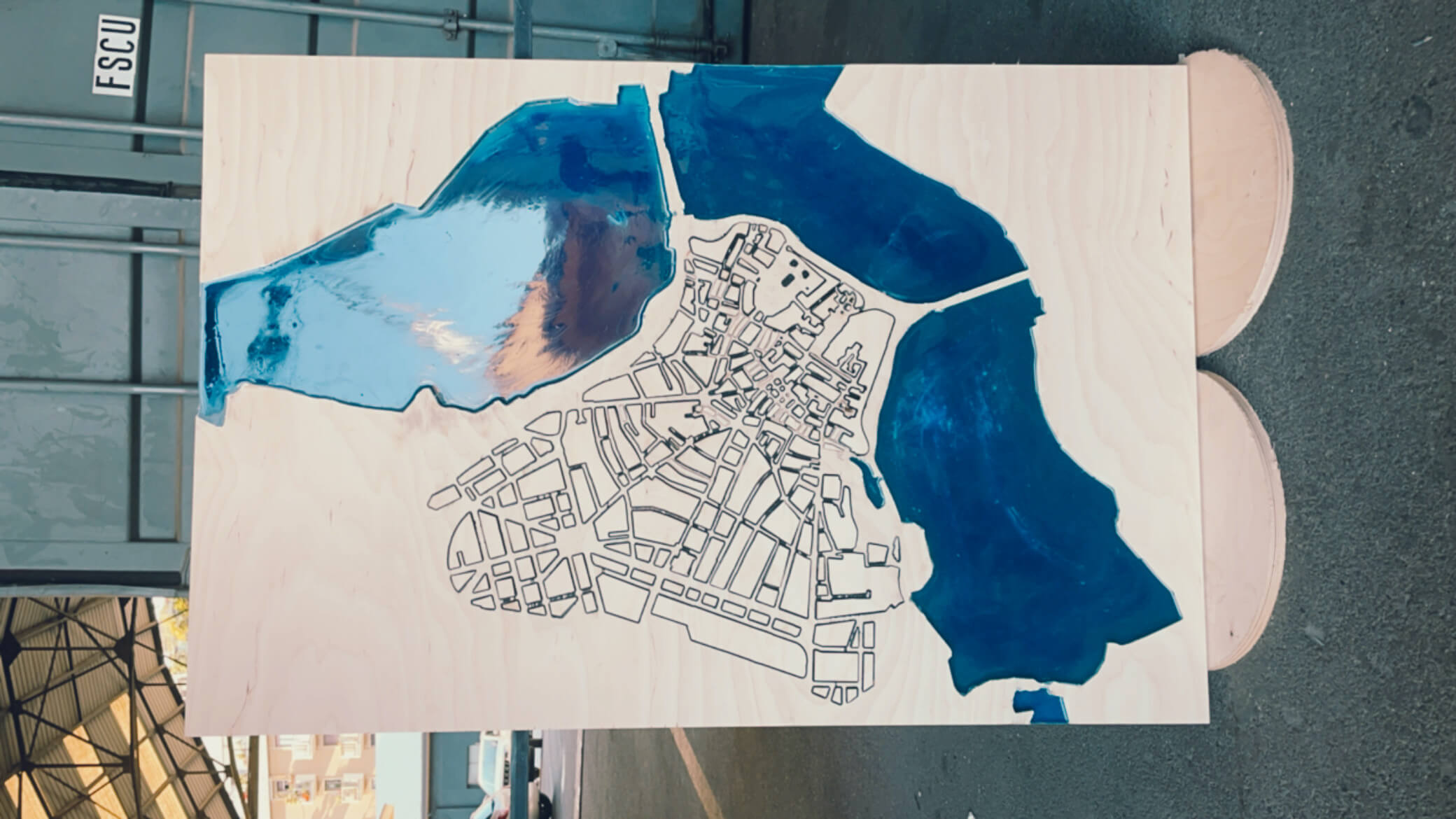
When all the seedling is glued I take the orbital and the dremel with the tip with the sandpaper and I pass the seedling in such a way as to make it as clean as possible. In the meantime the resin of the lakes has dried so I take off the paper tape that I applied and I pass the orbital and dremel also on the edges in order to remove the glue and the paint that remained during the past processes.
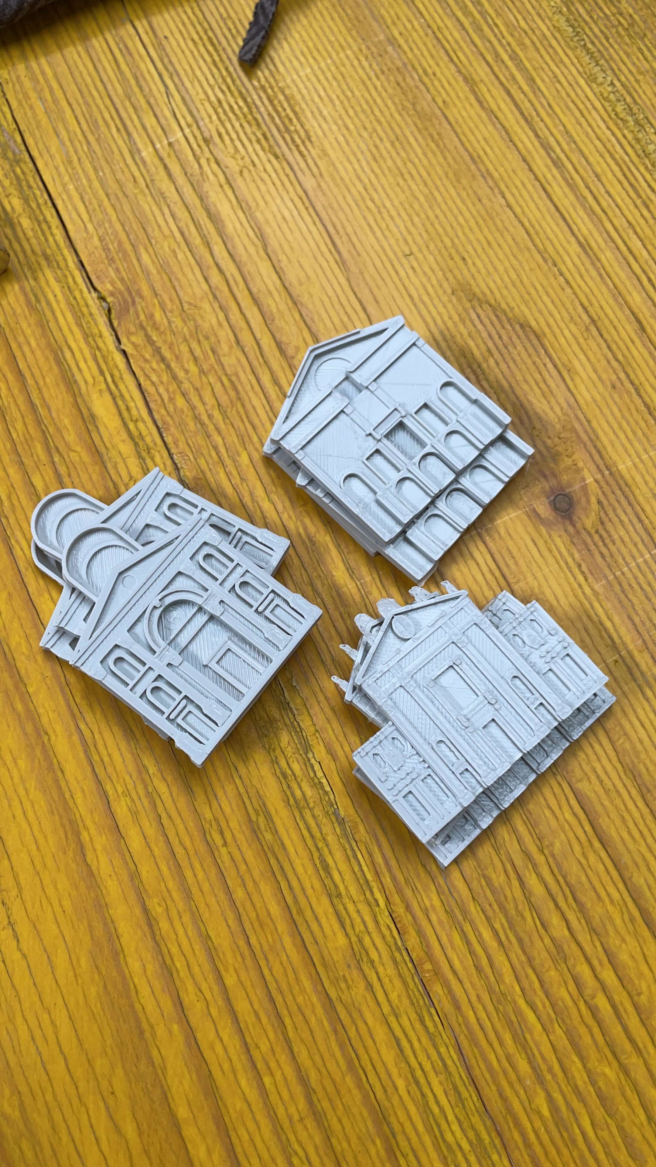
After doing this and cleaning my table, using the 3D printer, I print out the important buildings in my city and then apply them to my table before going on to apply epoxy to the whole table top.
The prints are the facades of the buildings, because to do the whole building would have been too big and would have increased the use of materials and costs considerably.
To make the prints look very detailed, I set the UltimakerCura software to use a smaller nozzle and a lower layer height.
This was the result:
- TABLE
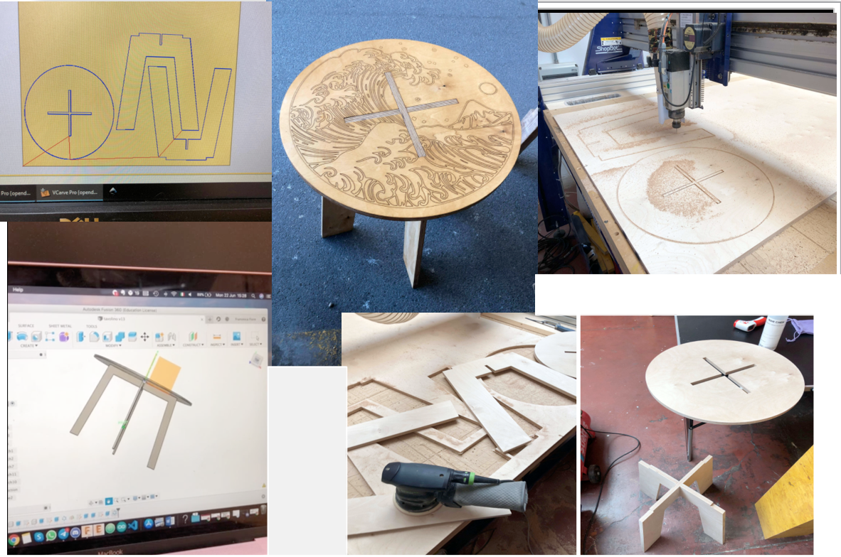
I thought of making a case for an acoustic guitar because I am a musician and I needed a case.
The idea was very interesting as well as certainly useful, but after a few days of study there was a problem: the weight-resistance ratio. The weight of the case, despite using wood and little else, would have been really heavy, considering that the guitar is not light either. In addition, the difficulty lay in milling the curved parts of the case, and to do this I had to study and make smaller tests first. I tried to do it on a smaller scale using the simple use of the lasercut, but with a small prototype in front of me I realised that the weight would certainly have been my enemy and it wouldn't have made sense to carry around a case that weighed so much, also considering the weight of the guitar inside. Certainly the design was very nice and interesting but NOT more useful.
I also thought that it might be possible to keep the same design but with different materials, but even then the weight-to-strength ratio would have been too unbalanced.

To demonstrate what I'm saying, my partner Francesca Fiore and I did a test by milling a stool.
The stool works by interlocking and therefore uses the interlocking technique.
 .
.