Interface & Application Programming
ASSIGNMENT
Design and produce something with a digital fabrication process (incorporating computer-aided design and manufacturing) not covered in another assignment, documenting the requirements that your assignment meets, and including everything necessary to reproduce it.
INTRODUCTION
Using one of the previous boards, I used
(Processing)
and the (Arduino) program:
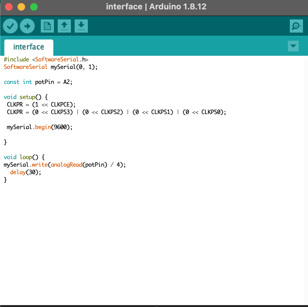
I used Arduino to upload my sketch, with my programmer, to the "MAIN" board.
The goal is to get my board to communicate with my PC.

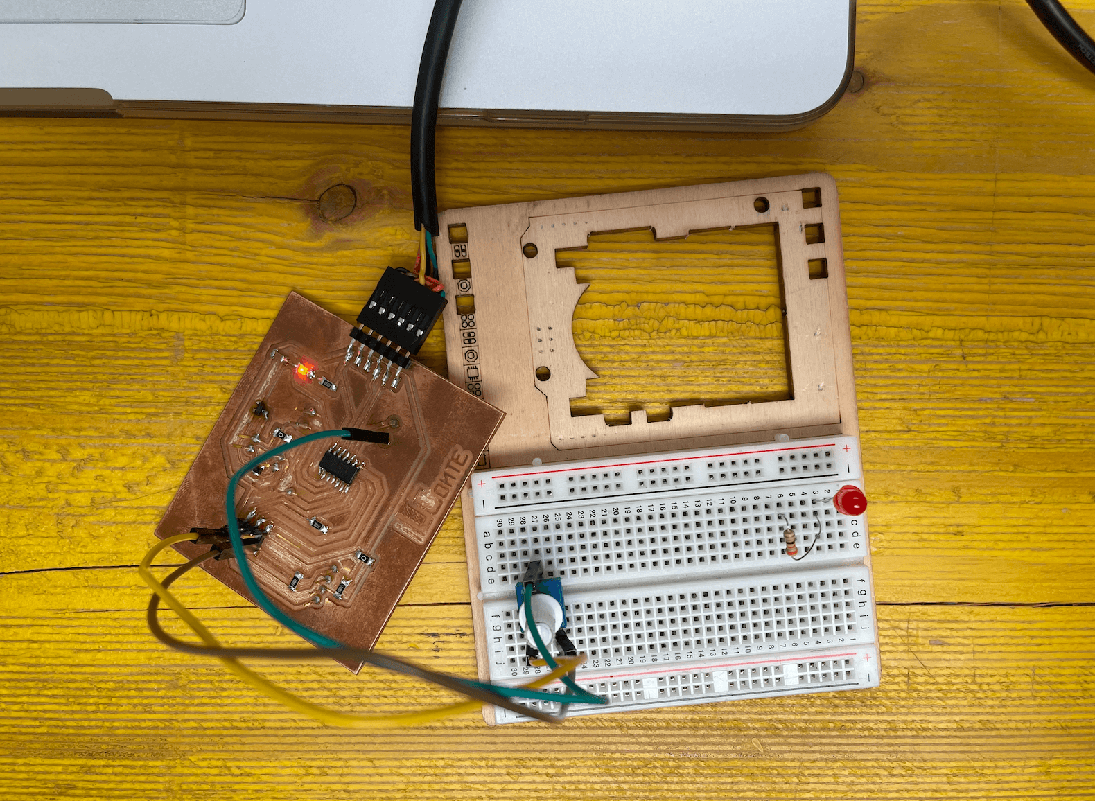
Once my board is programmed I attach the jumpers and potentiometer to the breakboard, attach the jumpers to the board to GND, VCC and a dedicated PIN, after which I attach the board to my PC with the FTDI cable and load my sketches.

|

|
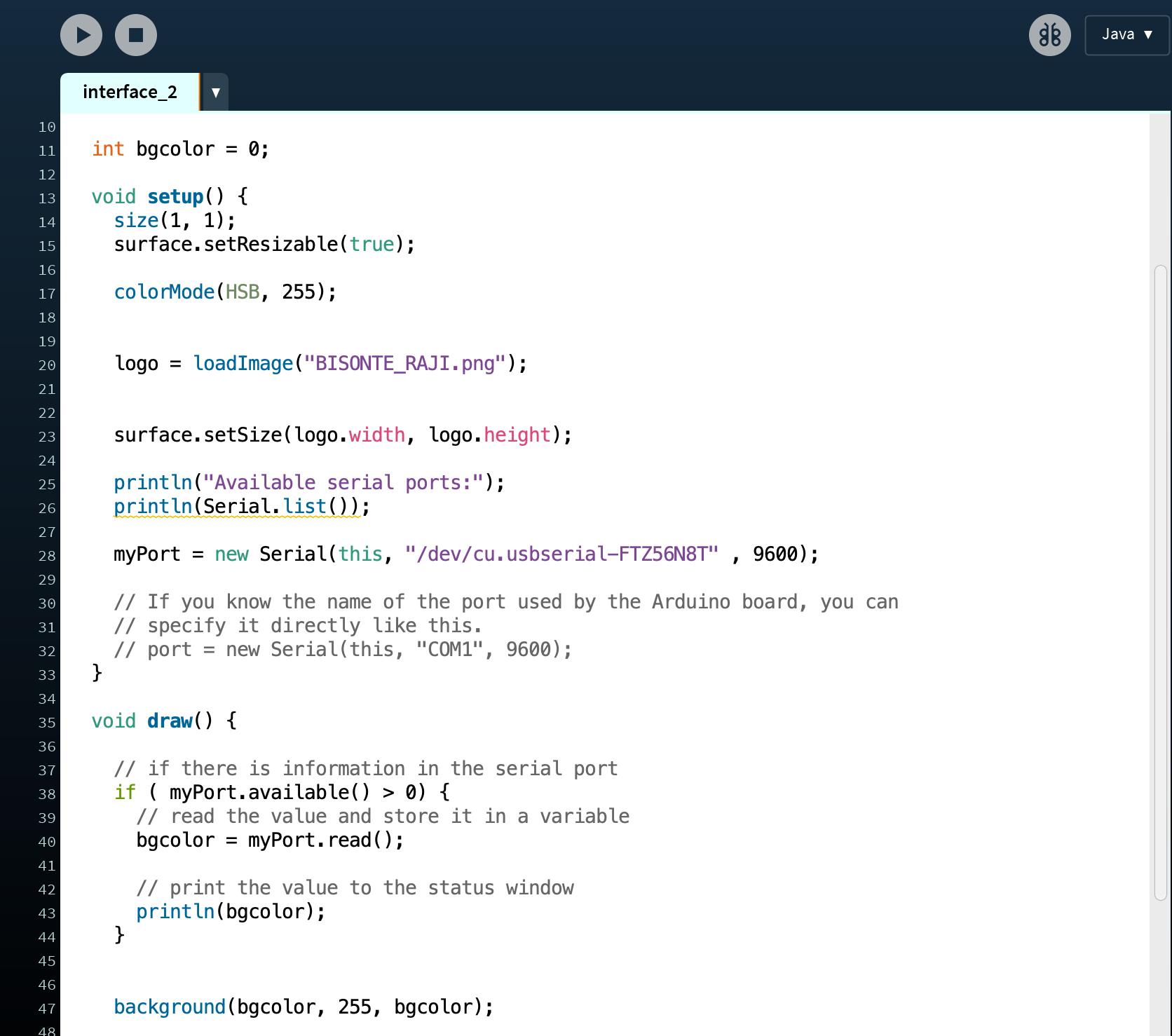
In the code I inserted my logo, the bison, and made the background colour change
The result is as follows:
EXPLANATION OF WHAT HAPPENS:
I have READ INPUT which gets a value.
This value is sent via SERIAL COMMUNICATION to PROCESSING which loads my image (bison) from the repository and adds a coloured background where the RGB value is the one received from the board via serial communication.
THE POTENTIAL sends the value to the board that is read by the board on the analog pin that in my case is A2
FILE
- BOARD
- SCHEMATIC