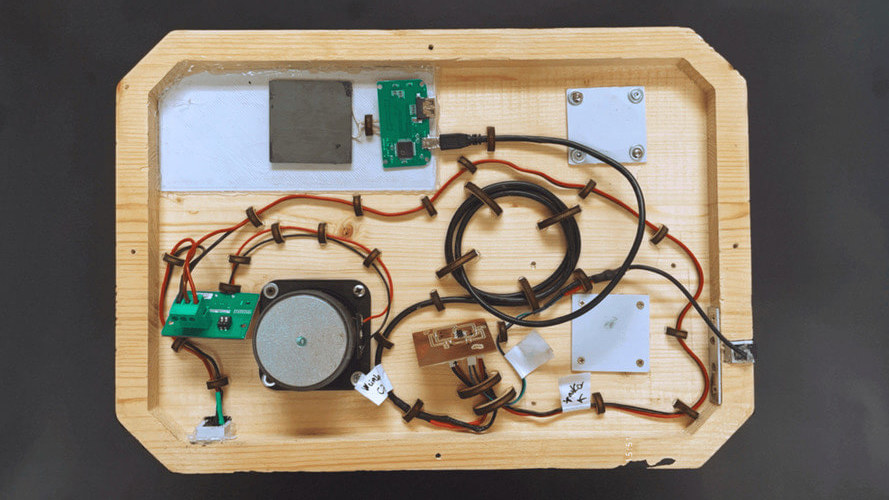
Final Result
The idea for this project came from wanting to create something new, useful and design-oriented. I was inspired by thinking about what I would like to do when I get home and relax: I would sit on the sofa with a glass of red wine and listen to music, recharge my smartphone and turn on a soft light, not too intrusive.
THOUGHTS
I first thought about the design of the project and wanted to create a simple design that wouldn't clash and could be easily placed anywhere in the house, from the bedside table to the dining room
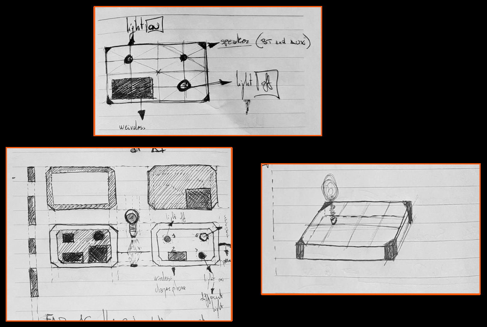
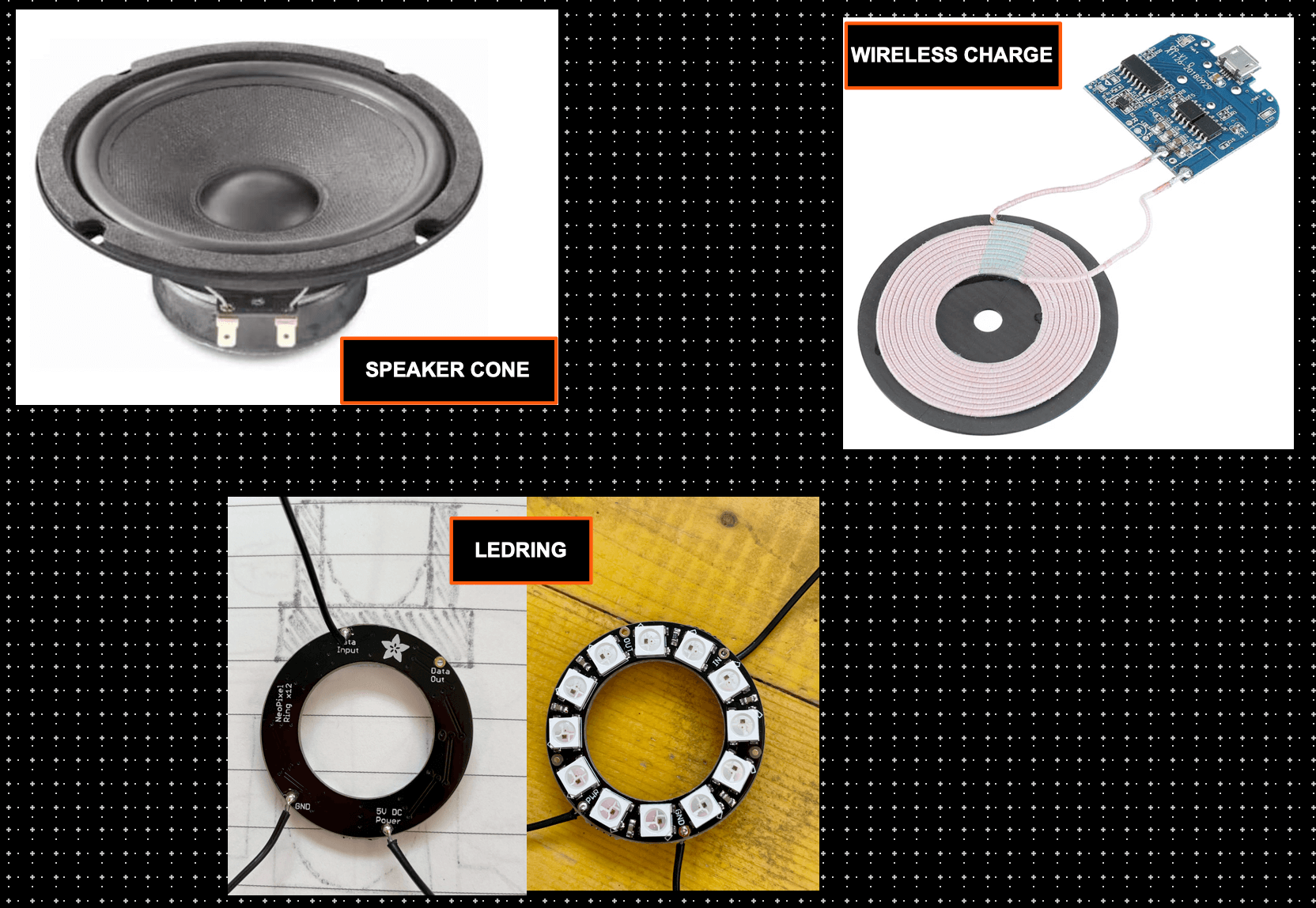
WHAT COMPONENTS DO I NEED?
REALIZATION
|
|
|
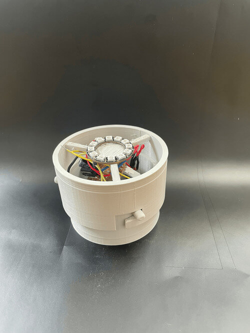
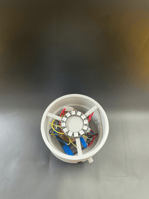
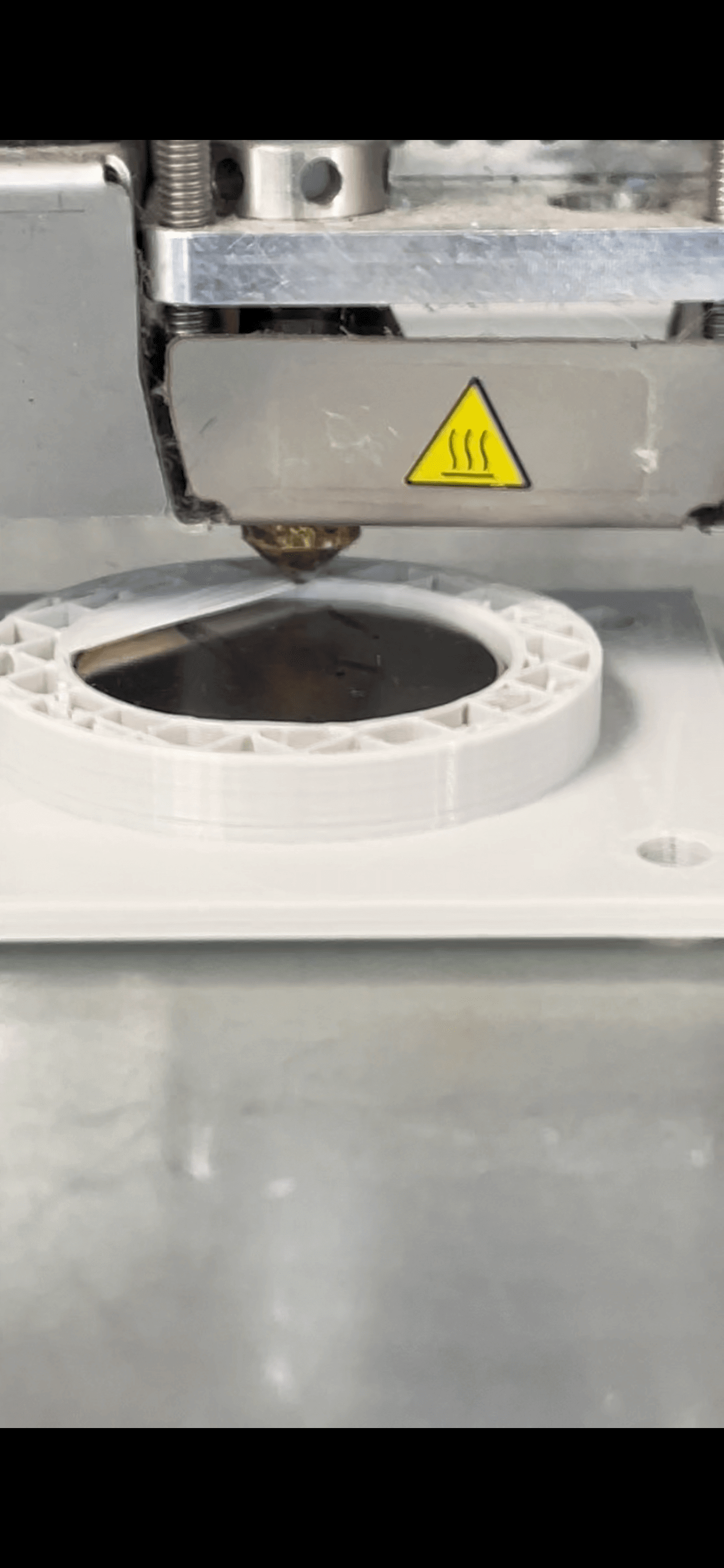
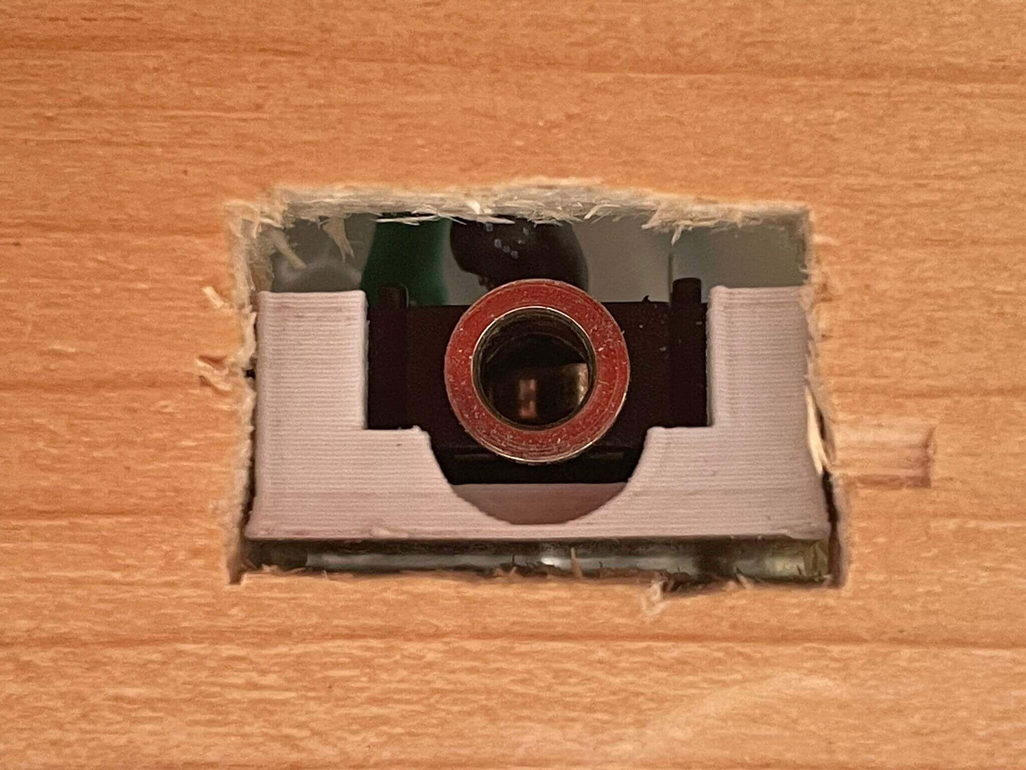
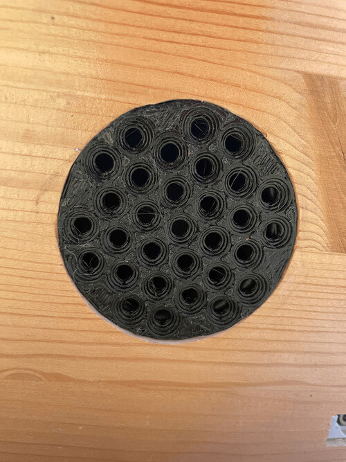
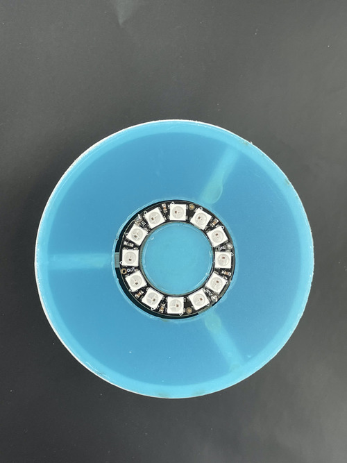
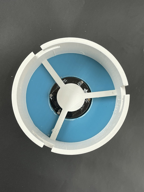
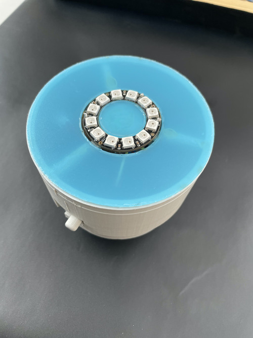
Now that my LedRing is working and the program is working, I have to think about its support and to do that I use the 3D printer. Since I need a magnetic base, while printing I put a magnet on both the LedRing support and the support inside the case so that they attract each other.
|
|
|
|
|
|
|
|
|
|
|
|
|
|
|
|
|
|
- In addition, in one of the two magnetic bases there would have been the magnetic fluctuation module but unfortunately there were problems with some electronic components so it could not be realised but it will certainly be an update that I will do in the future.
What does it do?
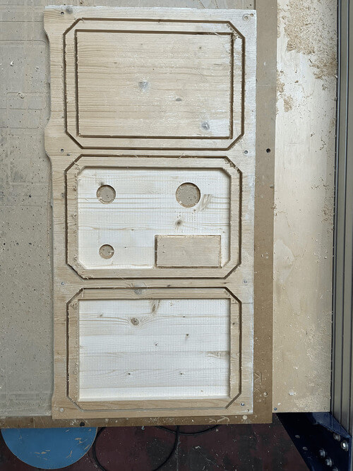
Who did what first?
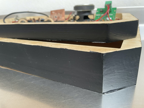
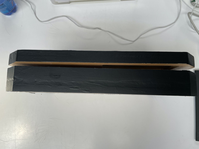
- First i made the box to contain everything so that i could see the total size and especially if there was enough space inside for all my electronic components.
What did you design?
- A hollowed out "box" that could contain all my electronic and non-electronic components.
What materials and components were used?
- MATERIALS: wood, PLA, metal, MDF, PCB
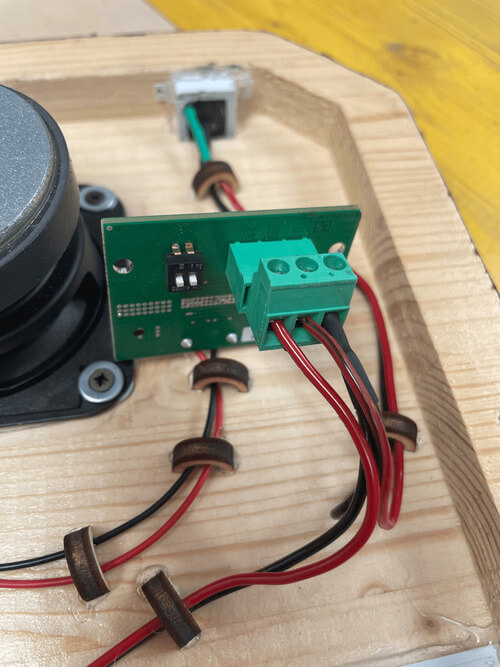
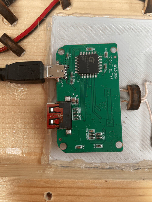
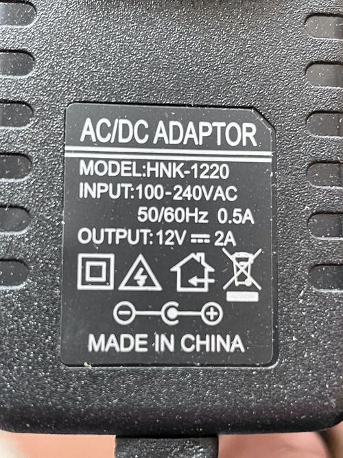
- COMPONENTS: speaker, wireless base, cables, led ring x12, attend_44, capacitor, led, resistors, batteries put in series.
Where do they come from?
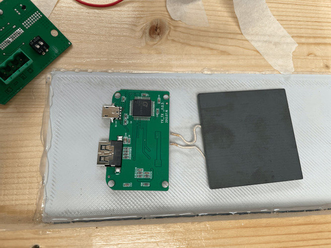
- Some parts i bought but only for time reasons (wireless charger, speaker cone), others i made myself in the workshop.
how much did they cost?
- Making an estimate once the project is finished, considering everything and the possibility of customising the object according to the home furnishings, I'd say about €500.
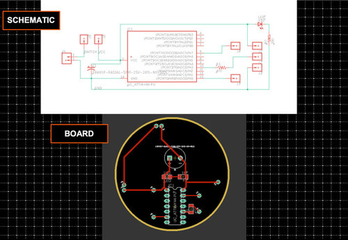
Which parts and systems were made?
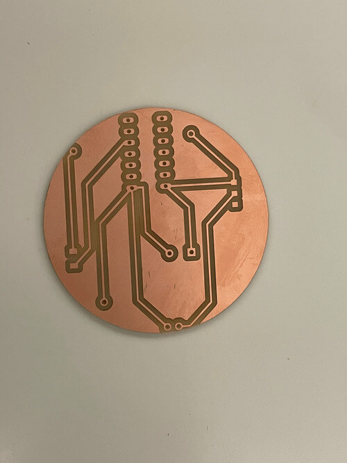
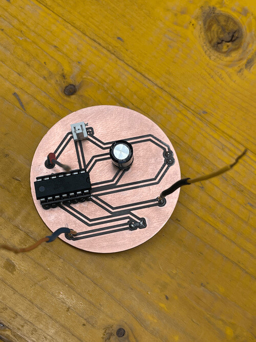
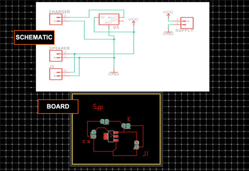
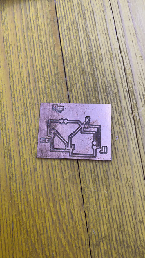
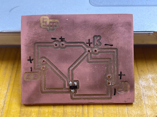
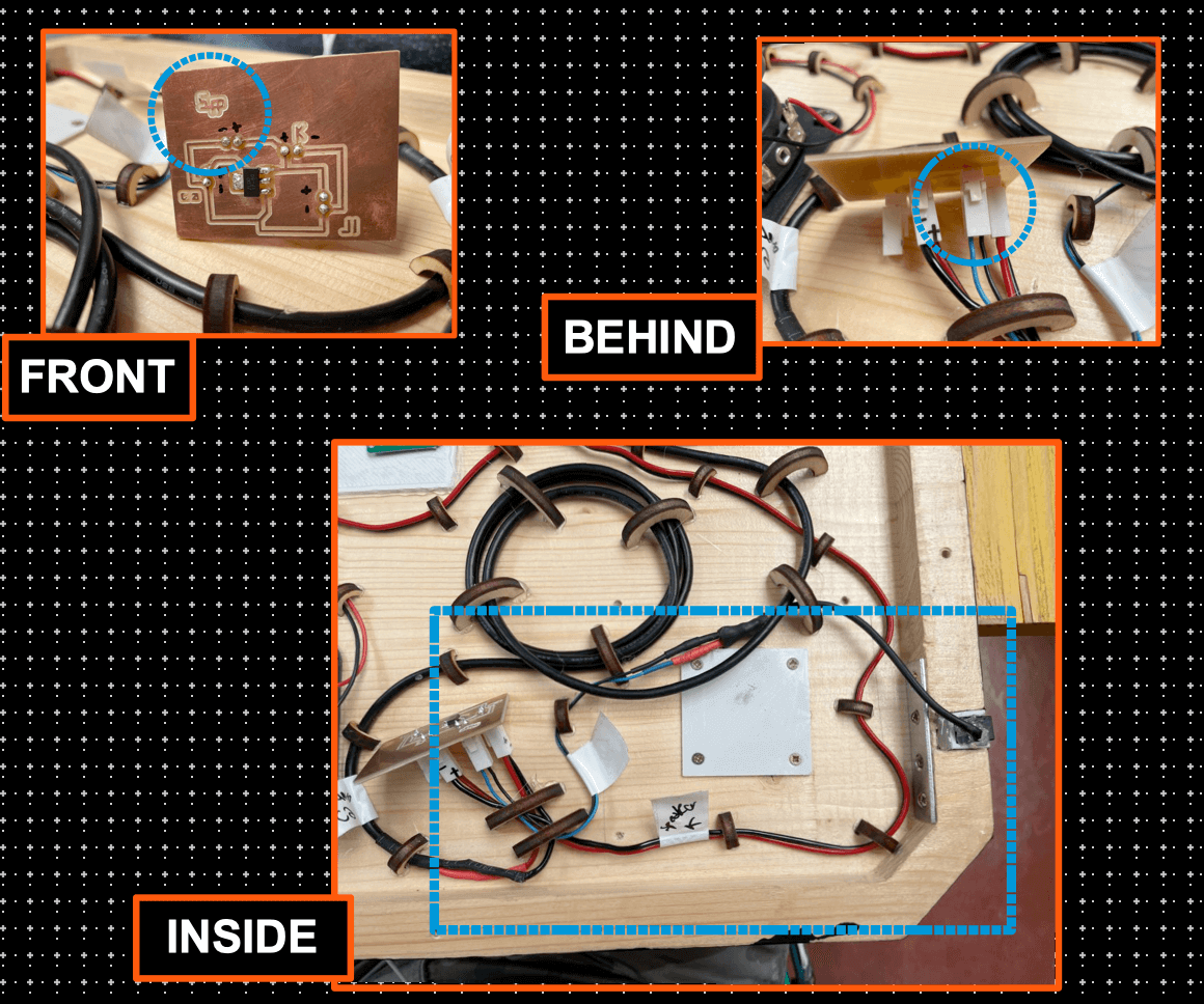
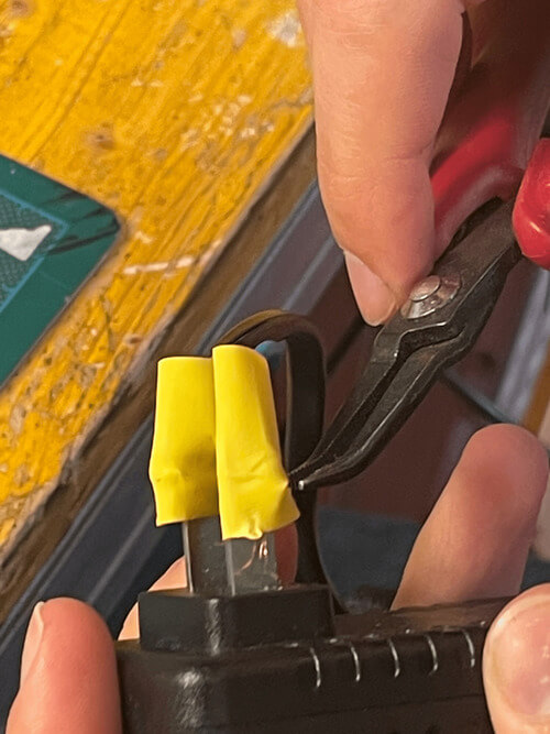
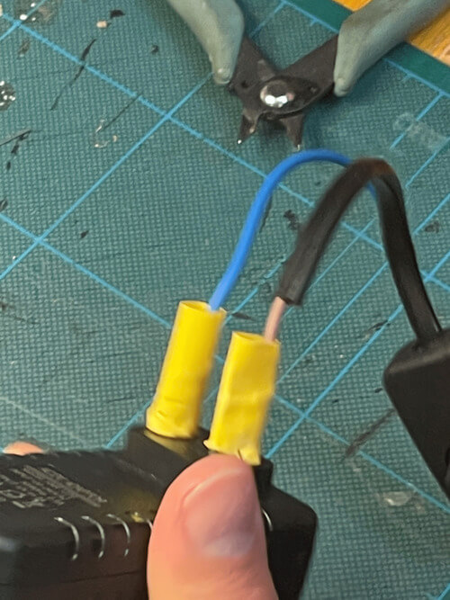
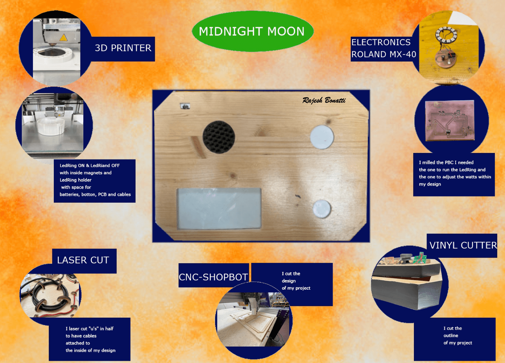
I made the general box of the project, I printed the magnetic bases (with the magnet inside), the support for the led ring that would contain all my electronic components, I changed and soldered all the cables, lasered the cable clamp, programmed my attiny_44, milled and soldered all the boards in the project (led ring and Voltage Regulator), put vinyl on the outside of my project to make it look better.
Which proc esses were used?
- Milling
- Laser cutting
- 3D printing
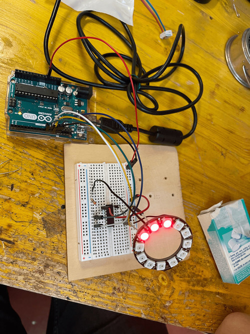
- attiny_44 programming
- Vinyl cutter to put a cover on the perimeter of my project
- welding
Which questions were answered?
- When I thought of this project I thought of the question: What would I like to have, to do in the evening when I got home and the answer was that surely my devide would be a bit drained, but I would like to listen to some music with a soft light.
What worked? What did not?
- In general everything worked, but in the details the LED did not change colour as I had programmed it, so I reprogrammed and revised it.
How was it evaluated?
- Interesting, but some parts needed modification: the led ring did not change colour and therefore had to be reprogrammed.
What are the implications?
- The implications are: studying the project in every "comma" and then learning things I didn't know before.
THIS IS MY PROJECT'S PRESENTATION
- CASE FINAL PROJECT
- LED RING SUPPORT
- CASE FINAL_1 stl
- LED RING_2 stl
- SPEAKER COVER
- LED RING CODE