Input Devices
ASSIGNMENT
WHAT DOES IT MEAN INPUT
Inputs are the data that the programme receives as input while outputs are the data that the programme transmits to a third party.
Introduction
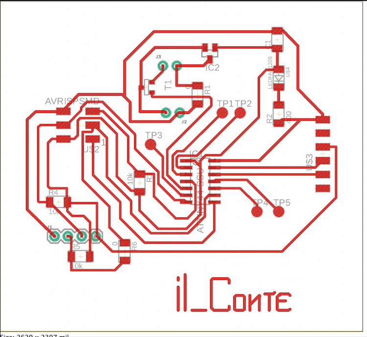
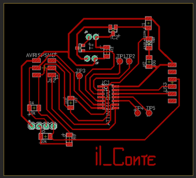
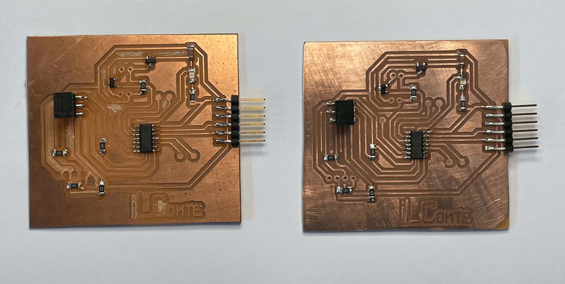
First of all I need to make two boards which communicate with each other and which I will also need for later assignments.
But for this assignment I only need one board.
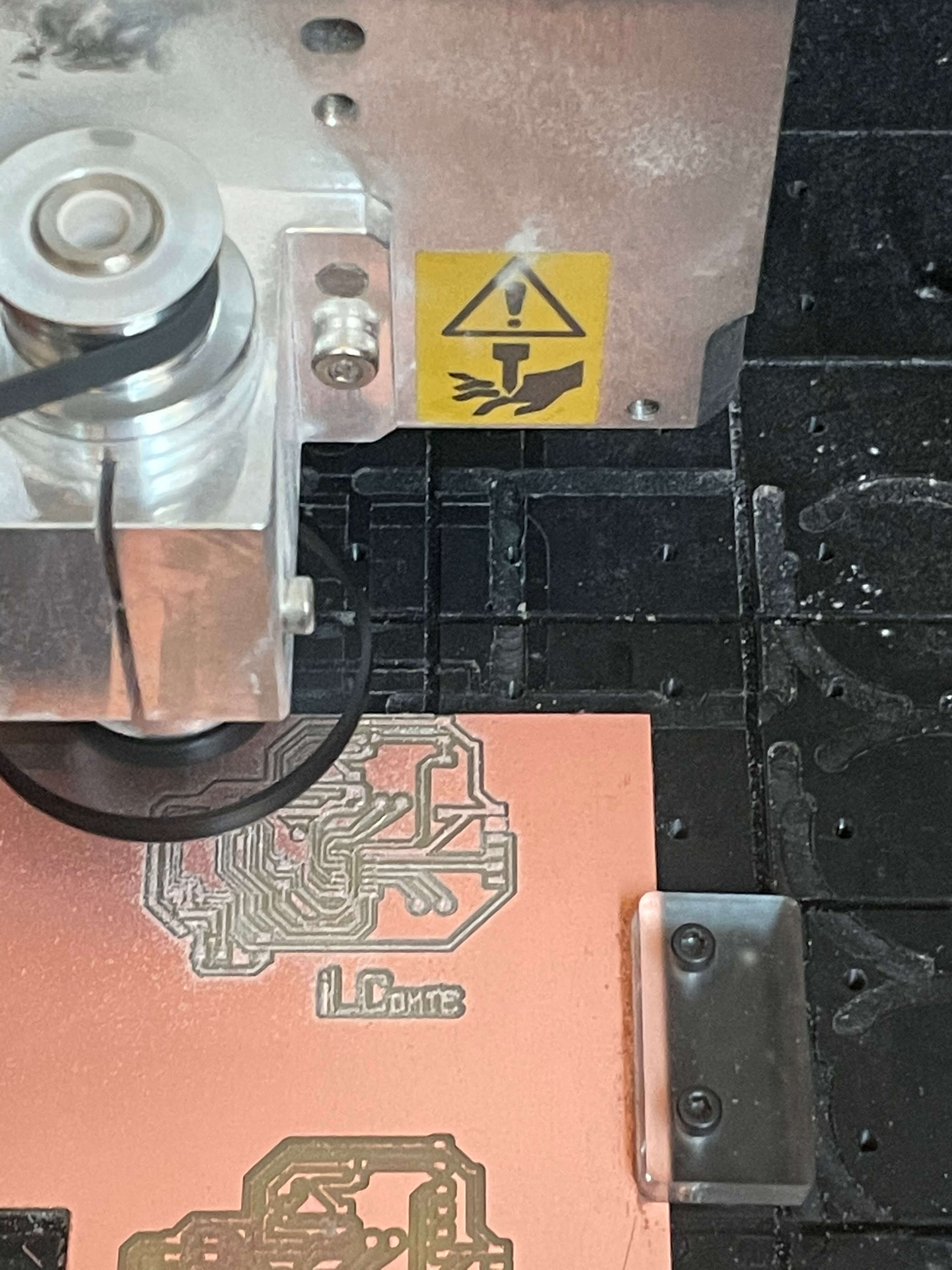
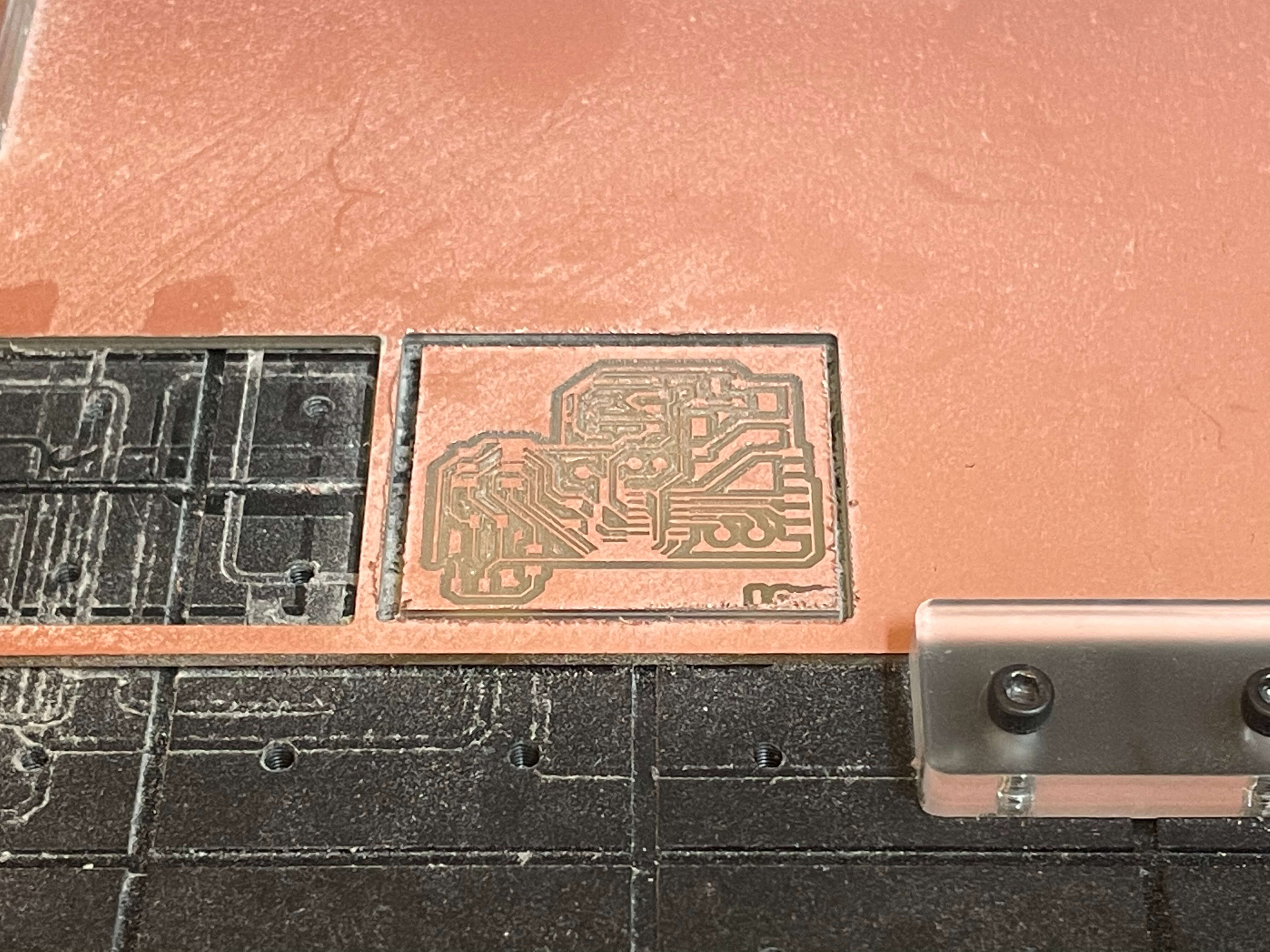
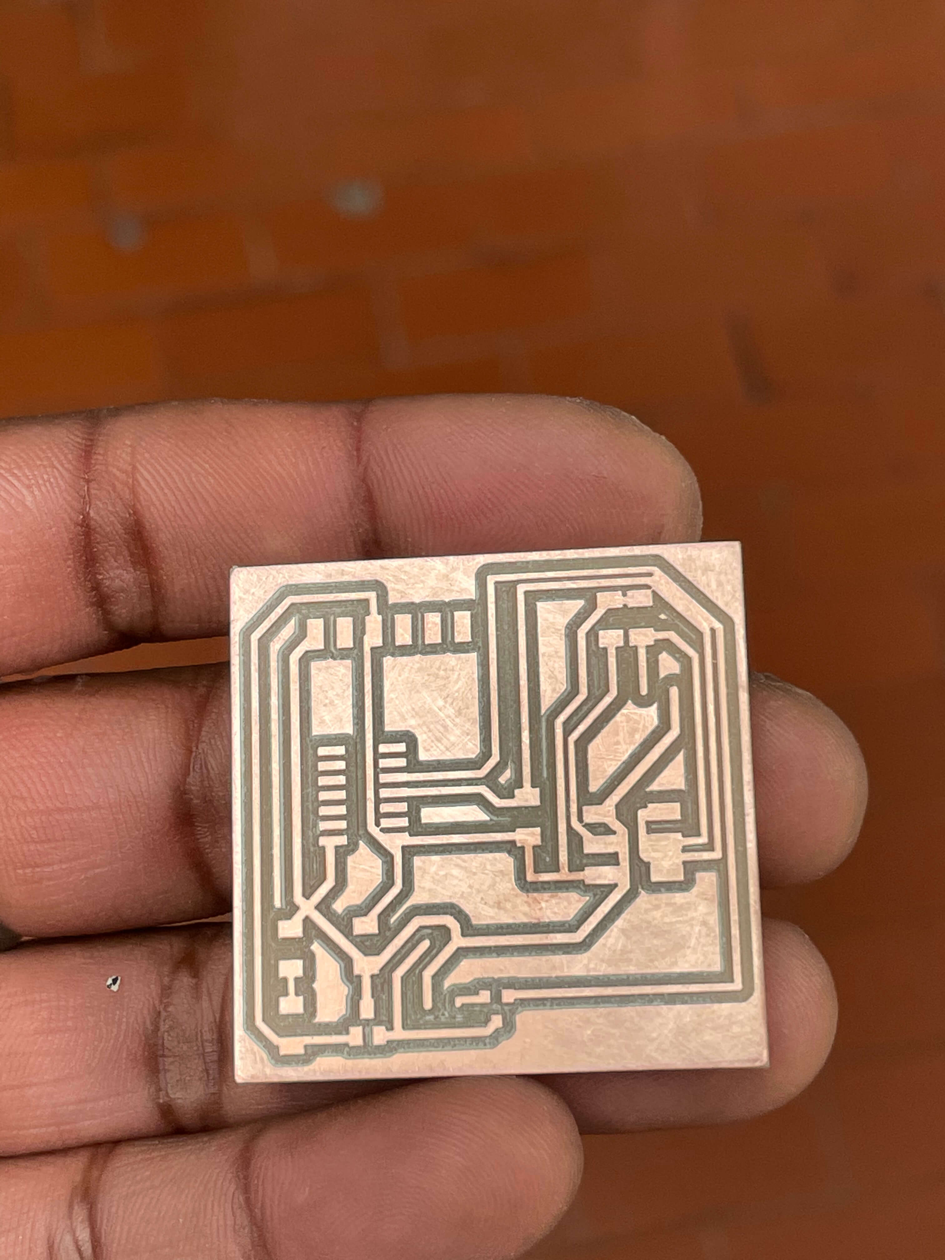
To make them I use the same technique I used in WEEK_4 by milling these two boards
|
|
|
|
|
|
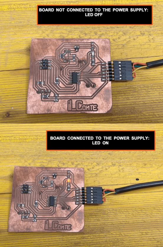
After soldering all my electronic elements on both boards, I check the function. To see if the board is getting power I put a LED on each of them to make sure
I need a BreakBoard, two buttons, two resistors, MALE-FEMALE jumpers. I put the buttons on the brackboard with the two resistors and the jumpers which I then connect to the PIN on my board.
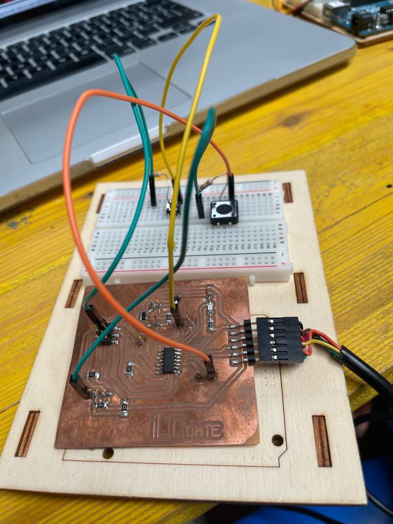
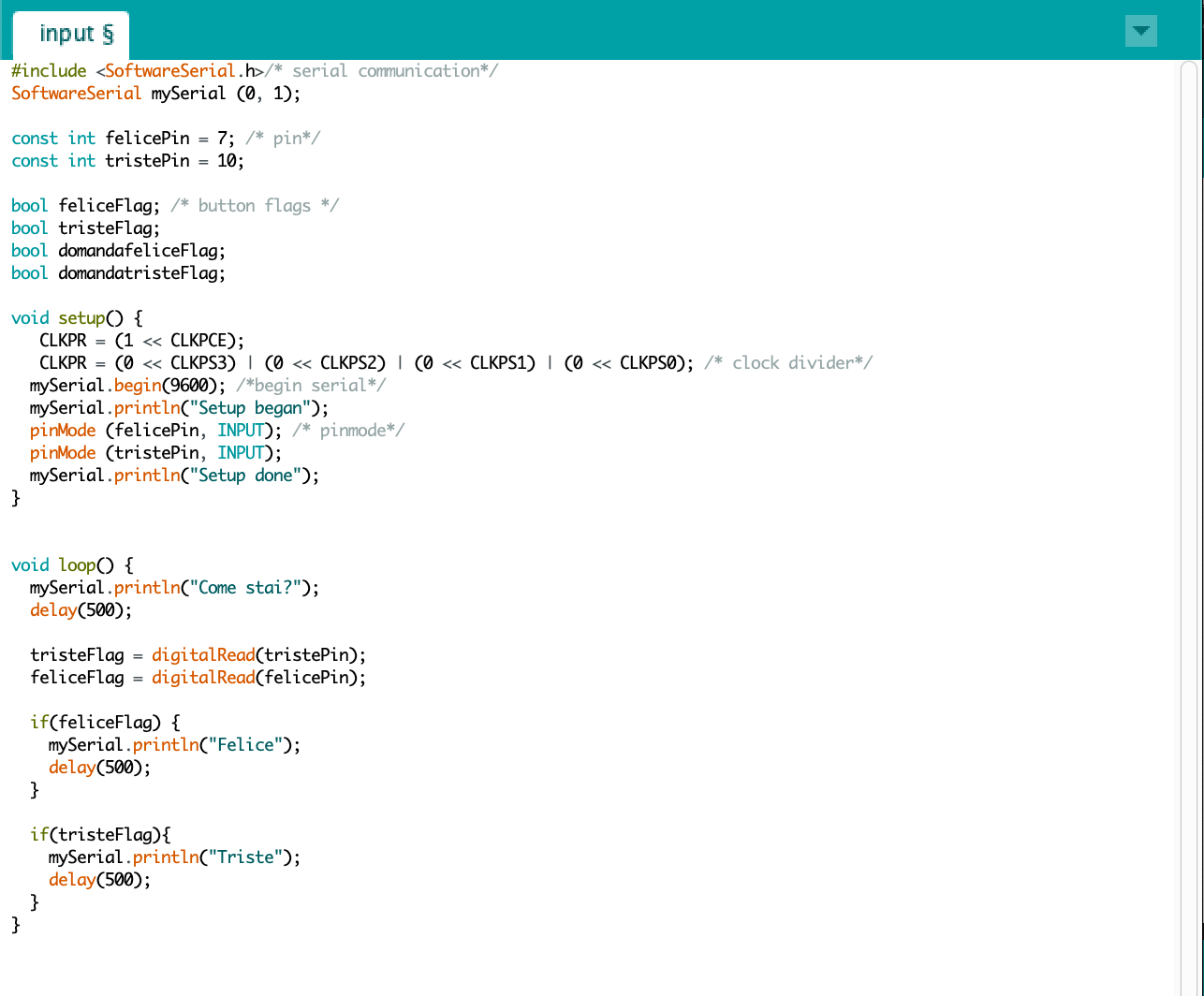
After that, I am ready to load a sketch onto the board: I plug the cable into the board, the LED lights up (so I understand that the board is receiving power) and I load the sketch via Arduino.
- I take a brack board with 2 buttons, 2 resistors, and jumpers.
- I take my board, my programmer, the ISP cable and the FTDI serial converter.
- first I connect my programmer to the PC via the USB-MICRO USB cable.
- Using the ISP cable, I connect my programmer to my board.
- I take the brack board and put the corresponding buttons and resistors with a GND bridge between them (you can also put another jumper directly on the board, but I found it more convenient to do it this way);
- Then I connect the PINs of my BOARD (SCK, VCC, GND) with the pins of the push buttons.
- Once I have connected everything, for safety I check that the pins connected are correct and I can ascertain by checking the PINOUT of the micro controller and my EAGLE board for the pins of my BOARD.
- Now i'm ready to upload the sketch, but first i need to check that the settings are correct.
- I go to "TOOLS" and the following must be filled in some entries:
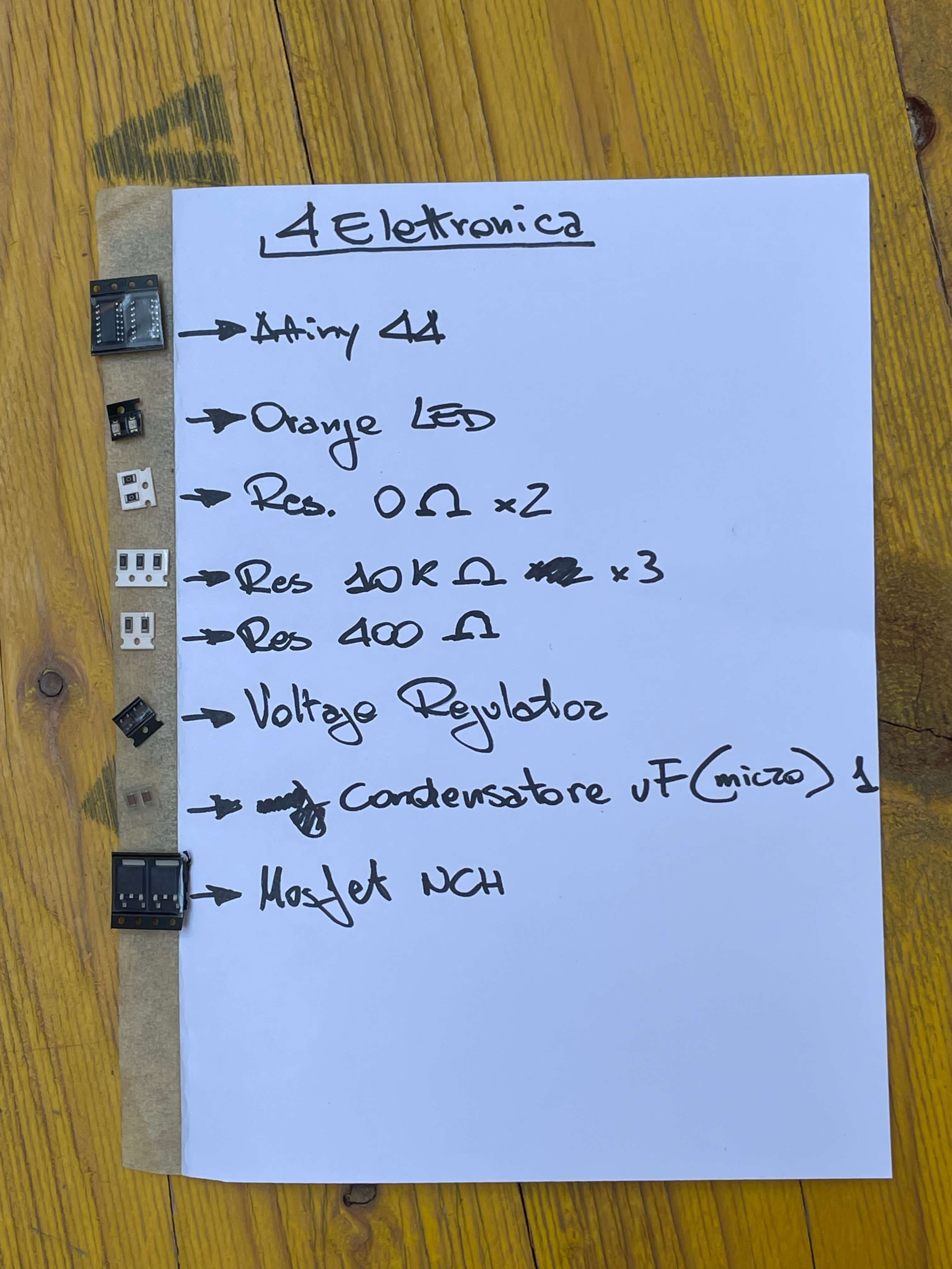
Attiny_44 no (boot loader)
CHIP: Attiny_44
CLOCK: 8MHz (Internal)
PORT: the one on your board
These are MY settings, but clearly if the board and the microcontroller are different, the settings will be different too.
FILE
- BOARD
- SCHEMATIC