Electronics Design
ASSIGNMENT
Individual Assignemnt
redraw the echo hello-world board, add (at least) a button and LED (with current-limiting resistor) check the design rules, make it, and test it.
characterize the specifications of your PCB production process
Group Assignemnt
use the test equipment in your lab to observe the operation of a microcontroller circuit board.
WORK FLOW
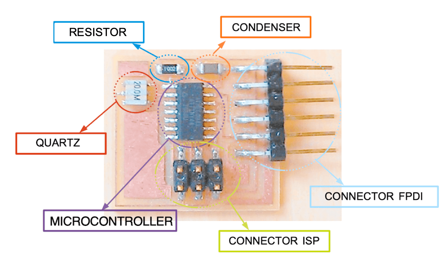
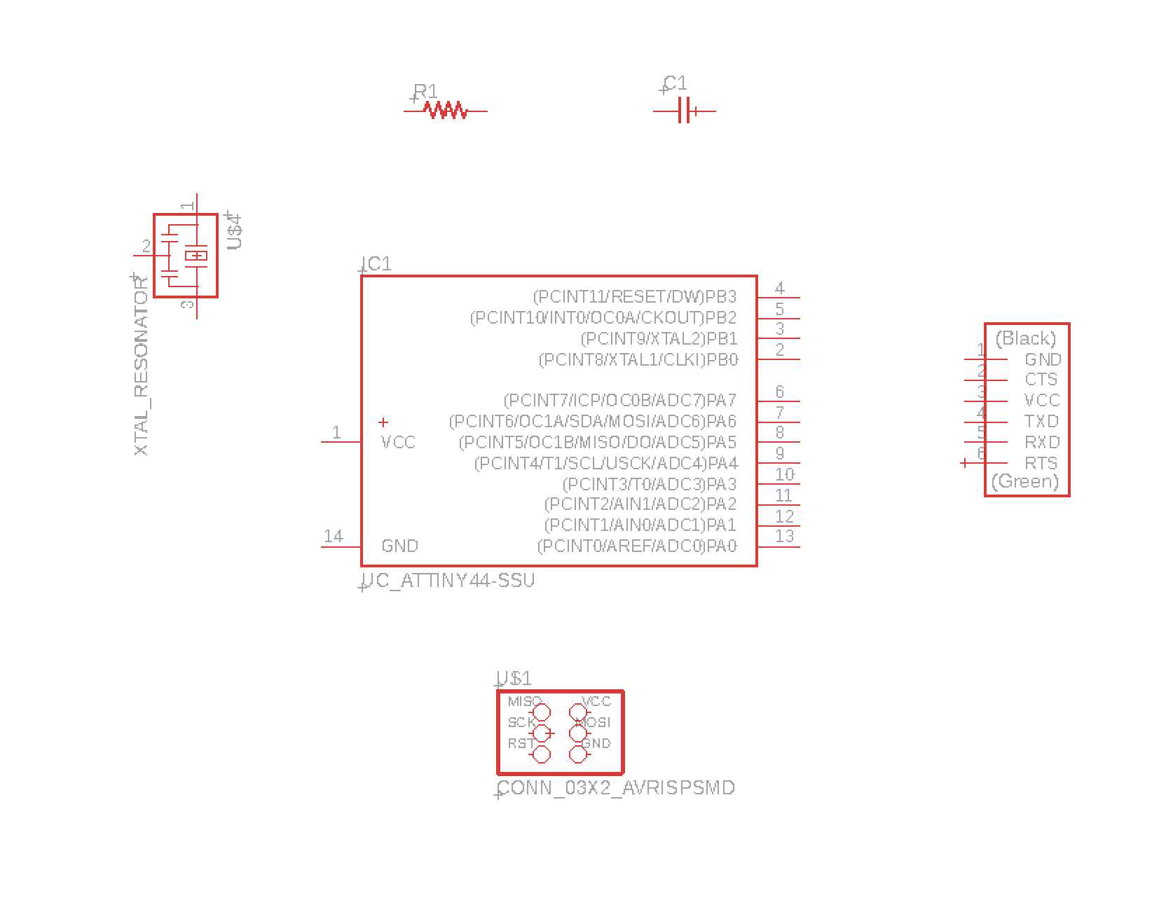
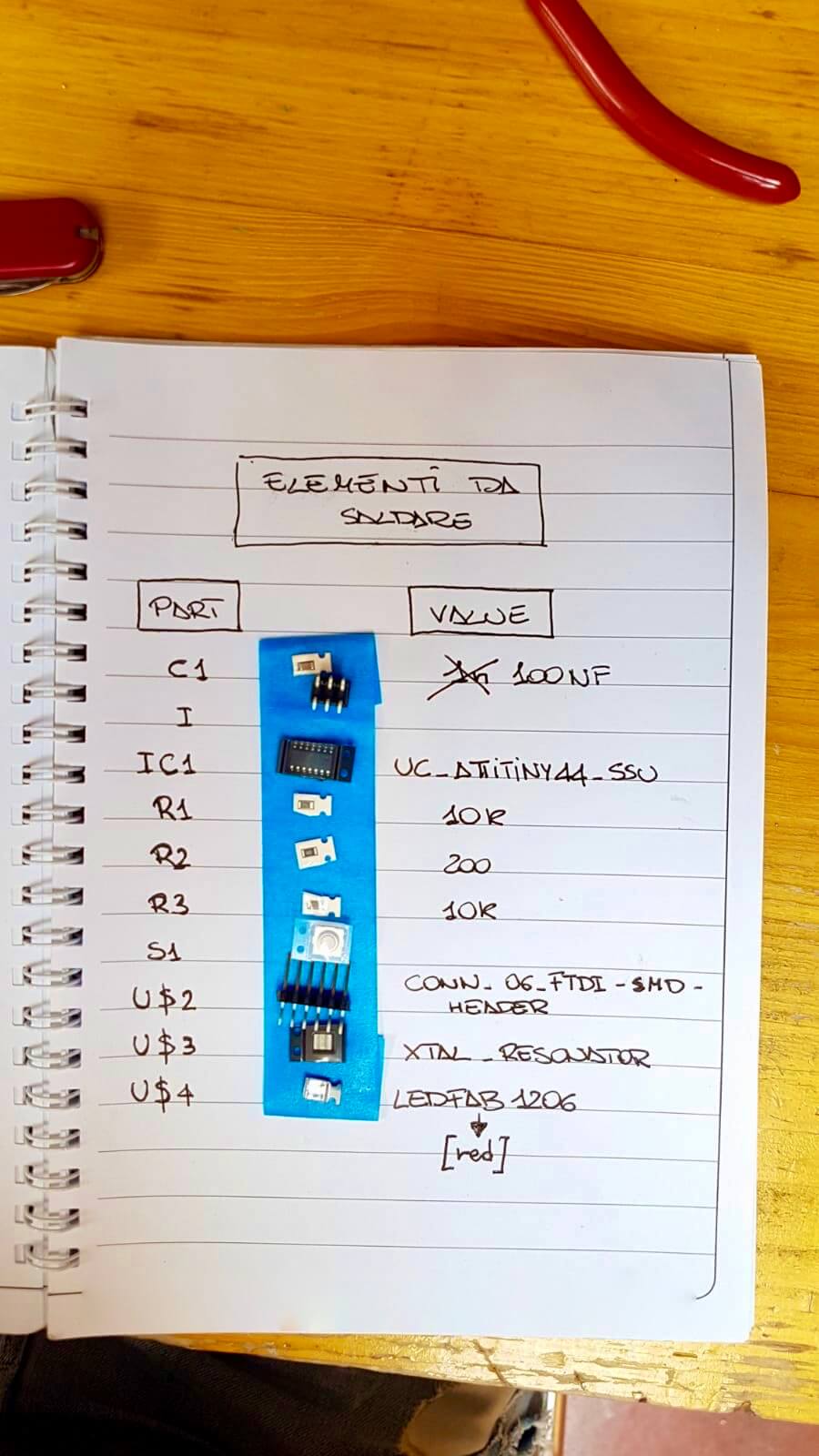
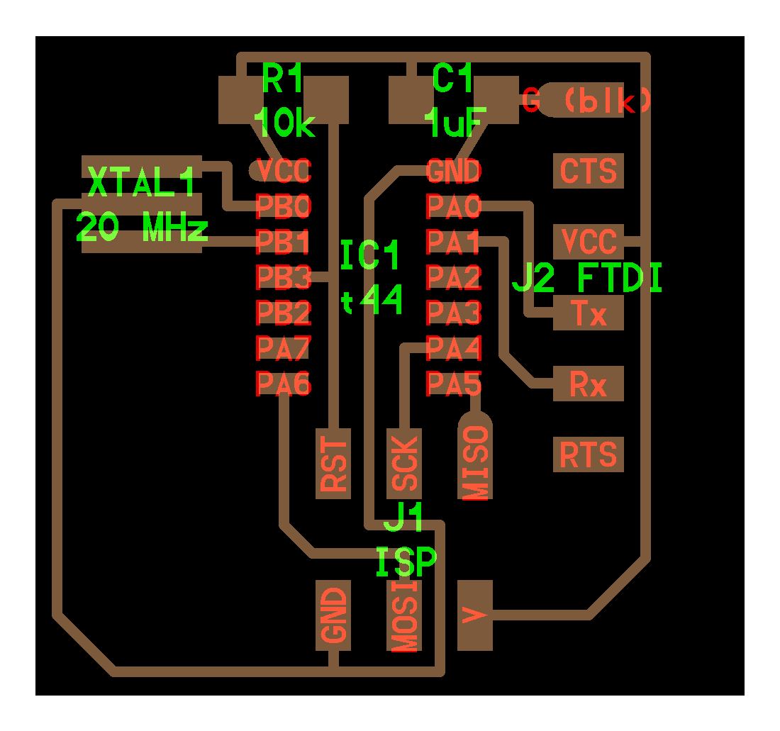
To draw a board we use EAGLE (by Austodesk Fusion 360). From the Fab website we go to choose which board we want to make (I've chosen the Attiny 44) and if we go to see the "components" item we'll see a picture where we'll have to understand what components they are and from there we'll have to add 1 LED and 1 BUTTON.
First of all we need to download the Fab "library" so that we have all the components we can/we need to use. Once saved we activate the Fab library and deactivate the ones provided by Eagle.
Eagle works first on a "SCHEMATIC drawing" and then on a "PHYSICAL drawing".
To start a new schematic drawing click on File-New-Schematic.
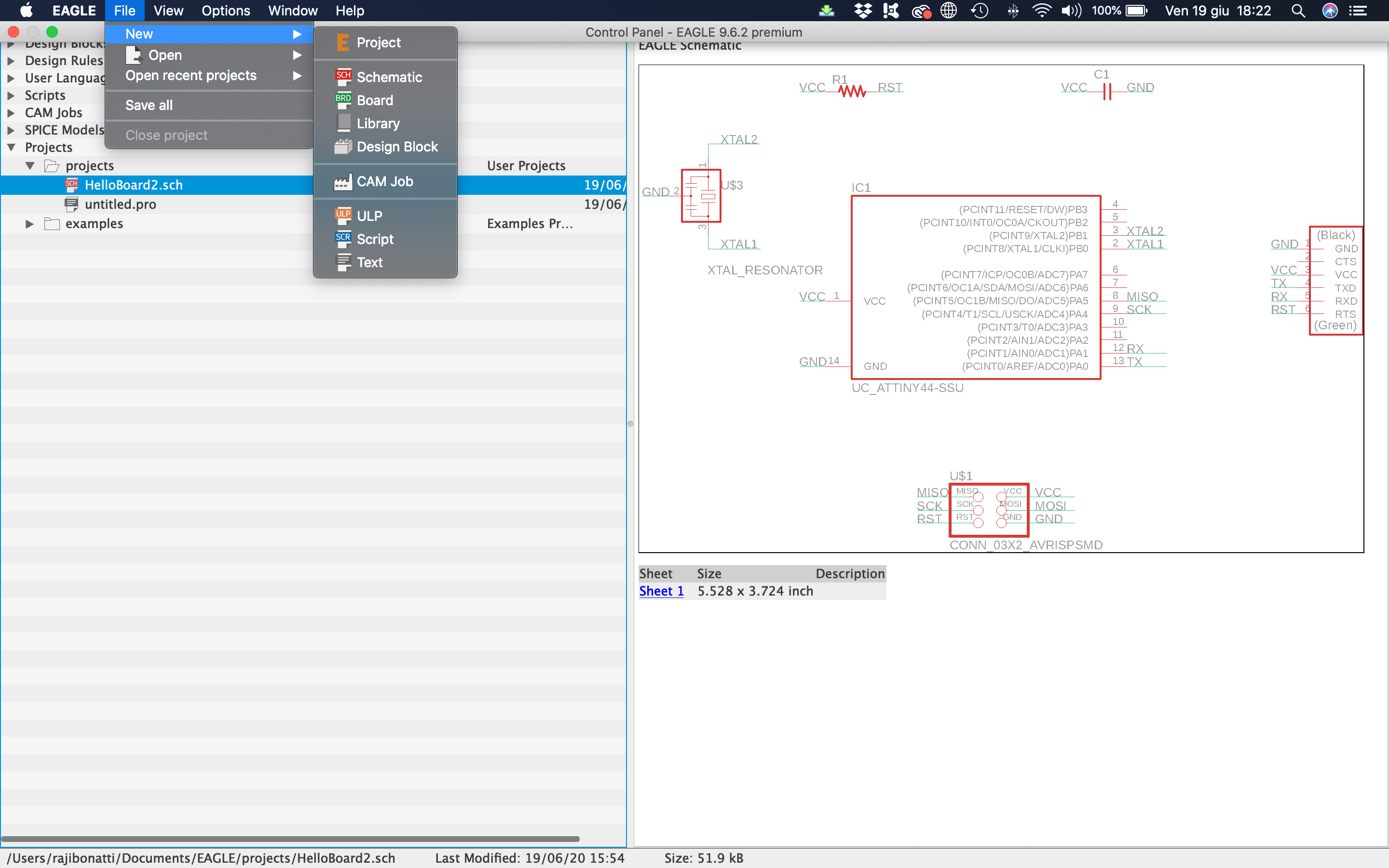
- fab.lbr
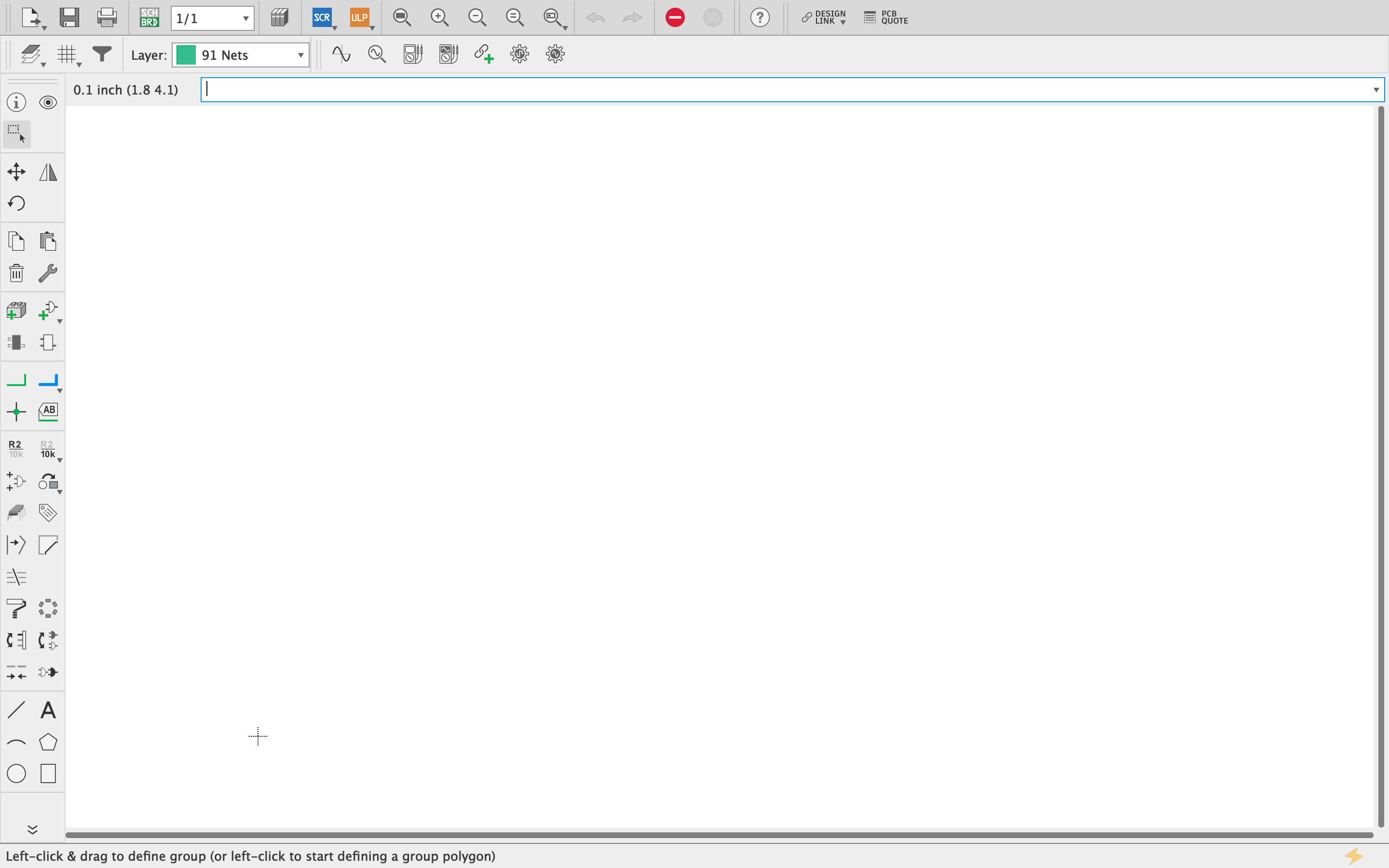
In the "SCHEMATIC" sheet you have to remember some main functions:
- Move= I move the elements;
- Add= I add elements;
- Name= link elements by name to avoid slaughterhouses;
- Delete= delete both net and elements;
- Value= indicates the value for all the elements that have a value (capacitors, resistors);
- Net= allows me to connect the different LOGICAL elements;
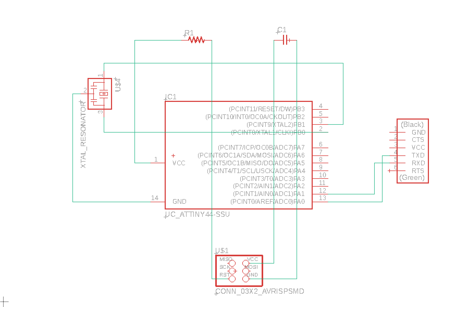
Once all our elements are in place, we start connecting them. There are two ways to connect them:
- We use the NET function and trace the connection;
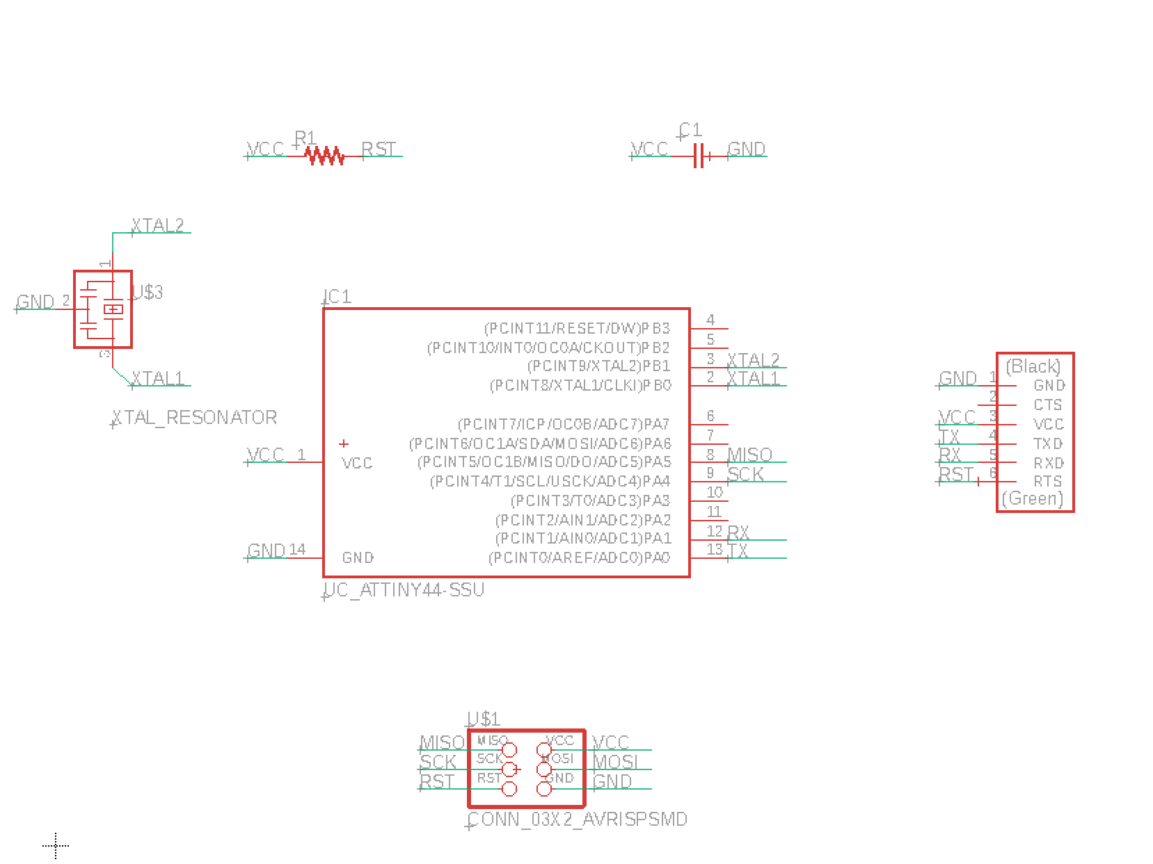
- Using the NET function we draw a short line where we name them and then connect our elements by name using the NAME function;
|
|
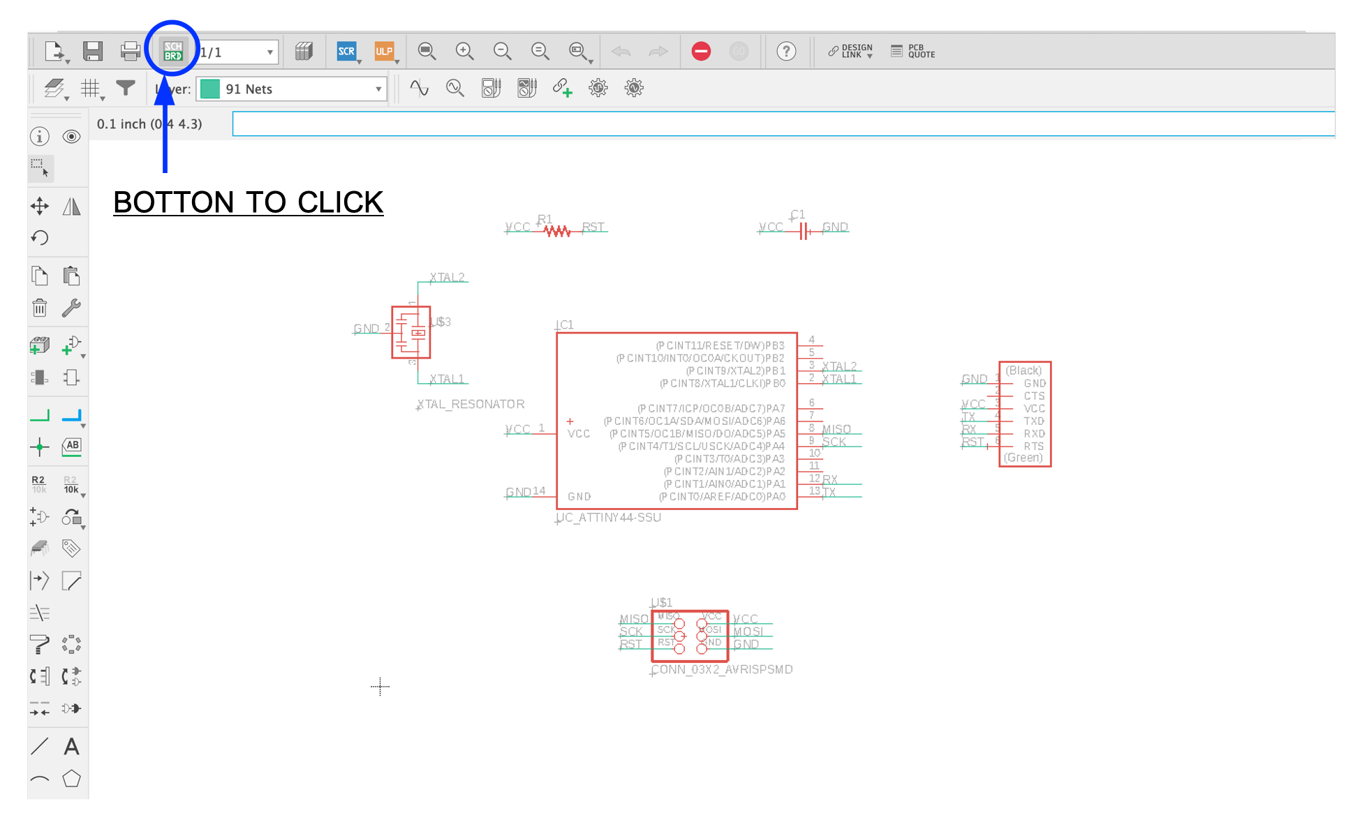
In the "BOARD" sheet you have to remember some main functions:
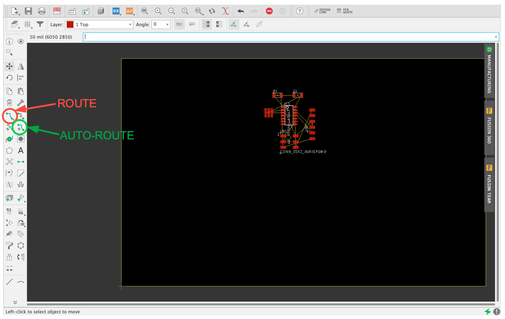
- Route= makes me make the PHYSICAL connections;
- Auto-Route= makes me automatically make PHYSICAL connections;
- Move= moves me the elements;
- Ripup= erases the tracks I made individually;
- Ripup;= with the ; erases all traces made;
- DRC= check the Design Rules;
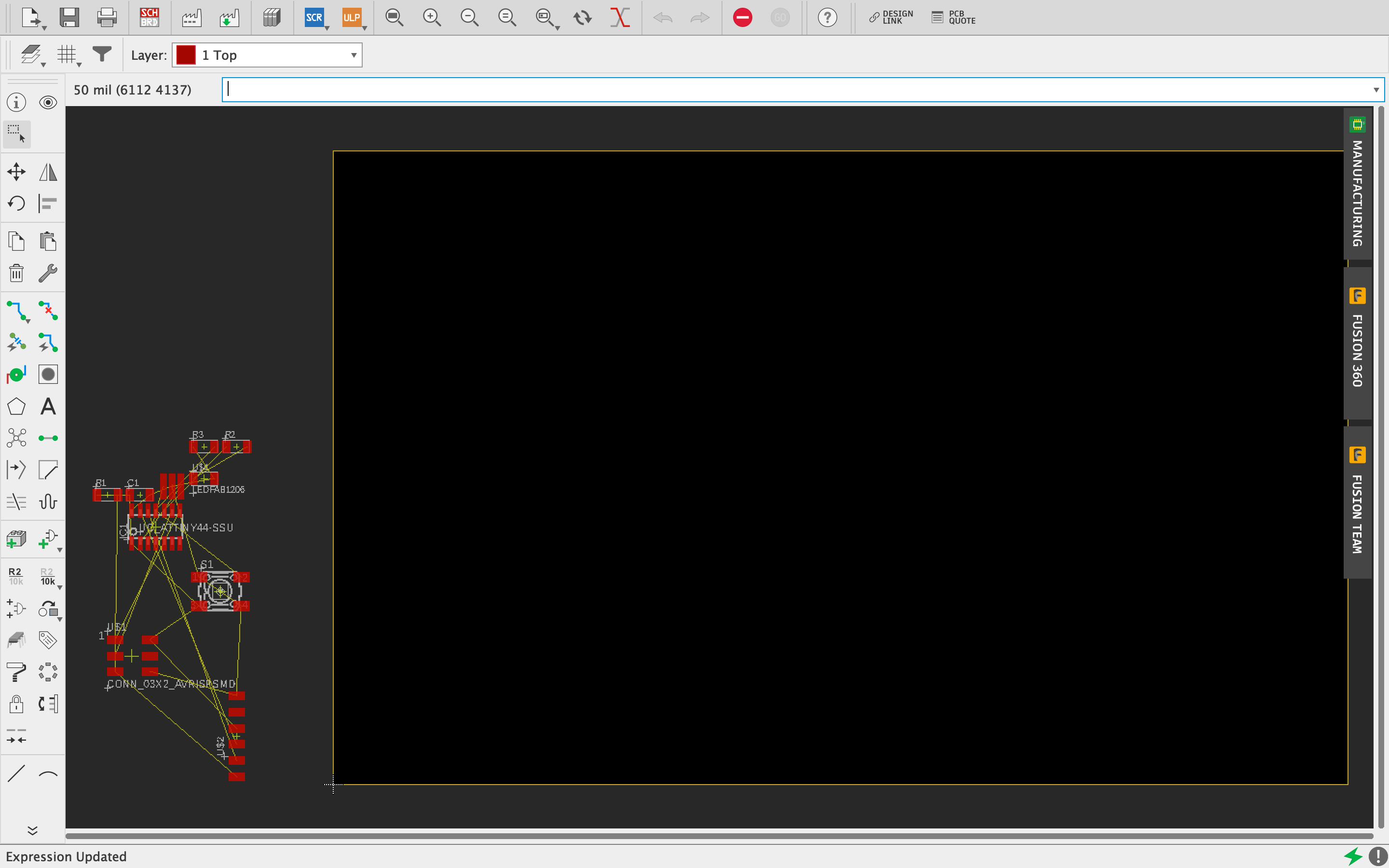
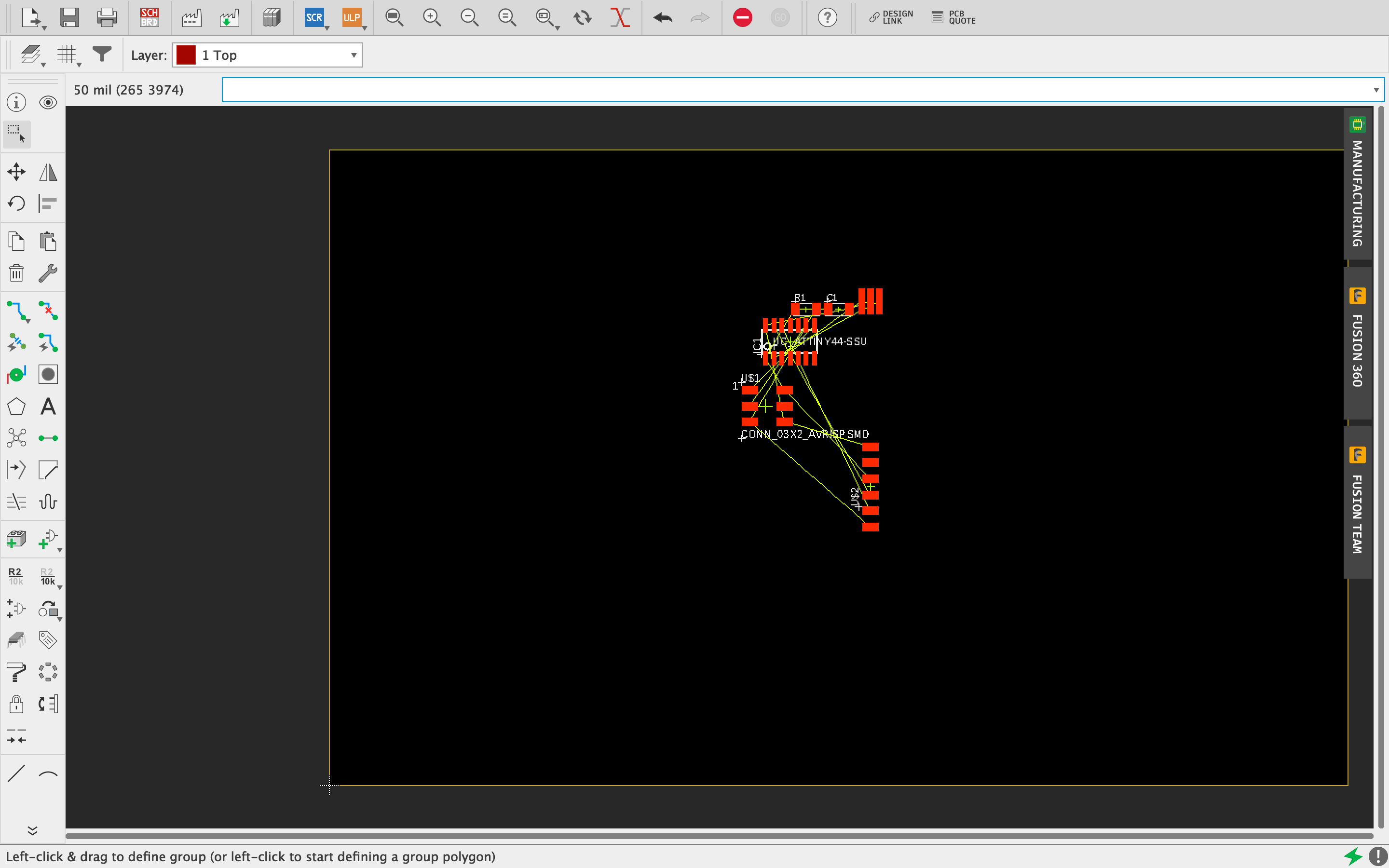
Using the "MOVE" function that I'm going to write in the top bar, I move all the elements in the best possible way so that I can then create the connections in the best possible way. Once selected the element I want to move, clicking on it with the right mouse button I can rotate it.
Thanks to the ROUTE function then I can go and draw my own connections; if our connections are many and very complicated I can use the AUTO-ROUTE function and the software will automatically make the connections and propose different solutions putting the best one first.
After finishing the various connections we have to outline our cutting field and to do so, first of all, we have to deactivate all the LAYERS except for the TRACK (red color)
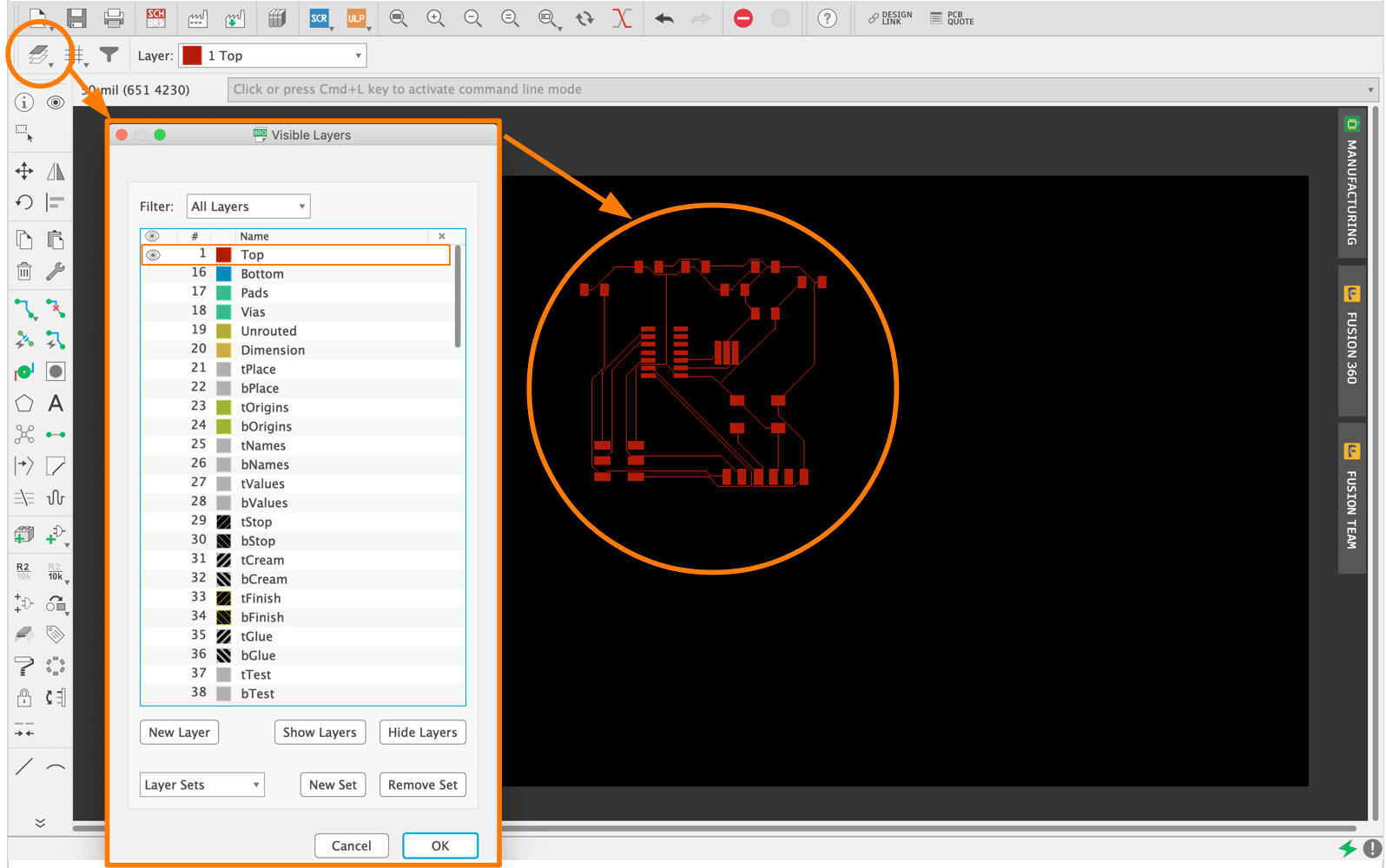
Once this is done, we must also delineate the perimeter of our board and to do so, we repeat the procedure as before, activating the DIMENSION layer and using the MOVE function I assign the perimeter so that the machine can then cut without problems
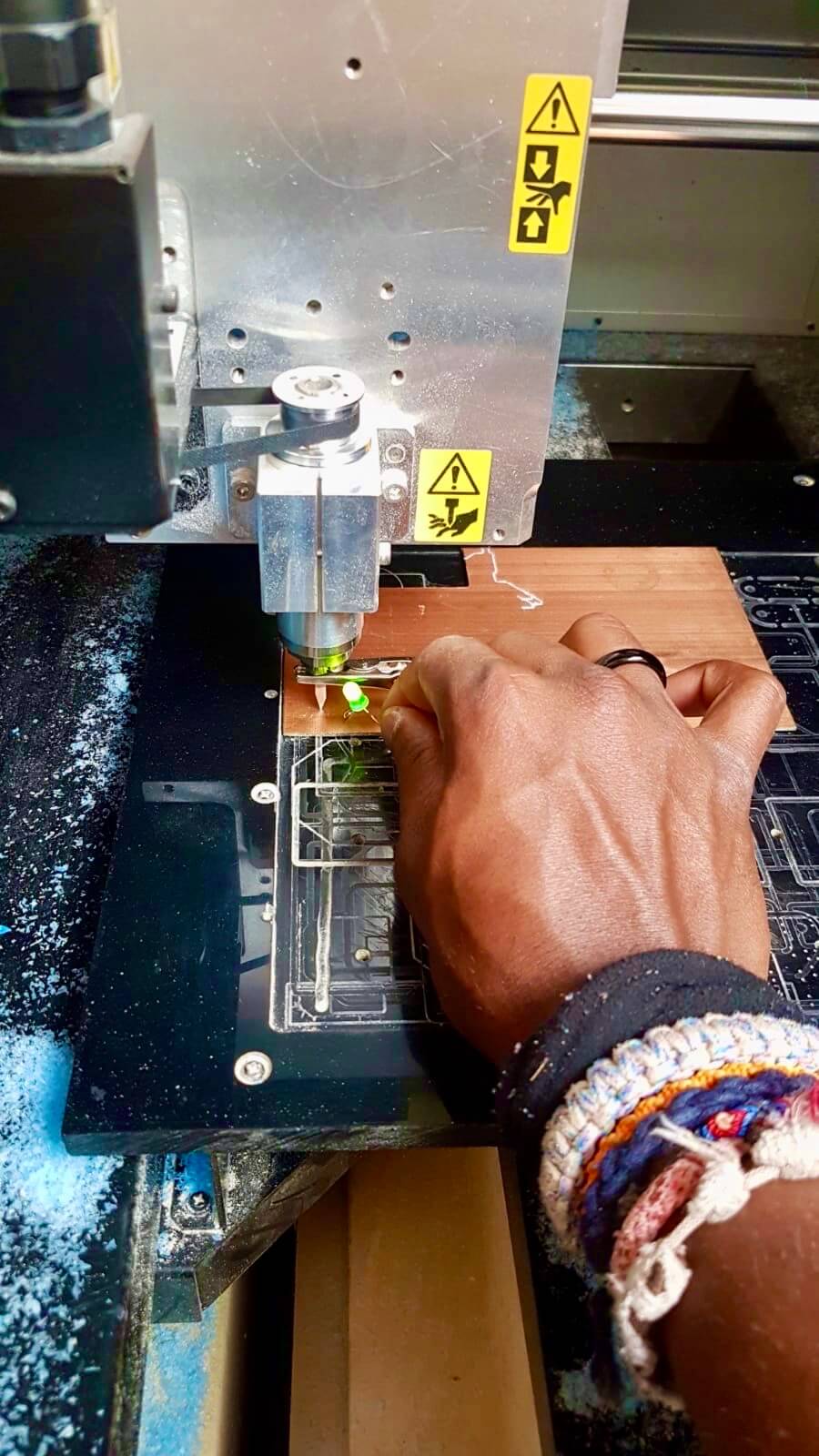
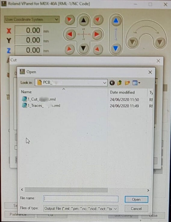
Once that's done, as we did in (Week-4), we go to the PC dedicated to the machine, import into our FILE and start.
First of all, we switch ON the machine, then we open the V-Panel program where I will set the X-Y-Z axis coordinates: as we did before, to set the Z axis we use the tool invented in Fab to understand when the tip touches our PCB panel.


|
|
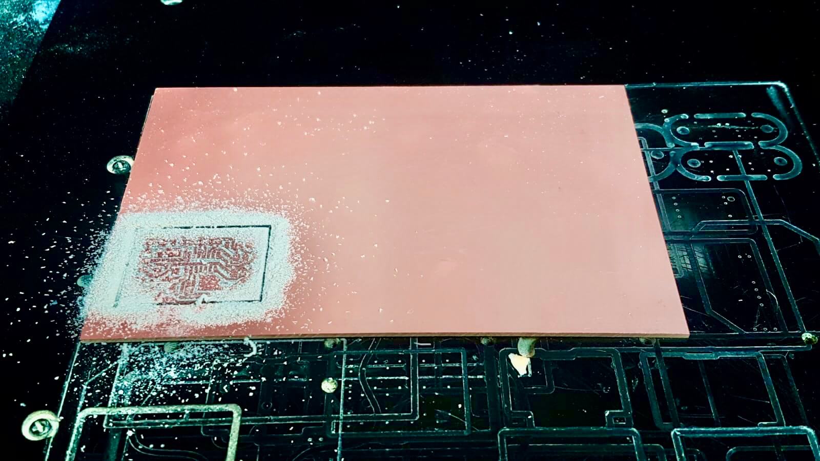
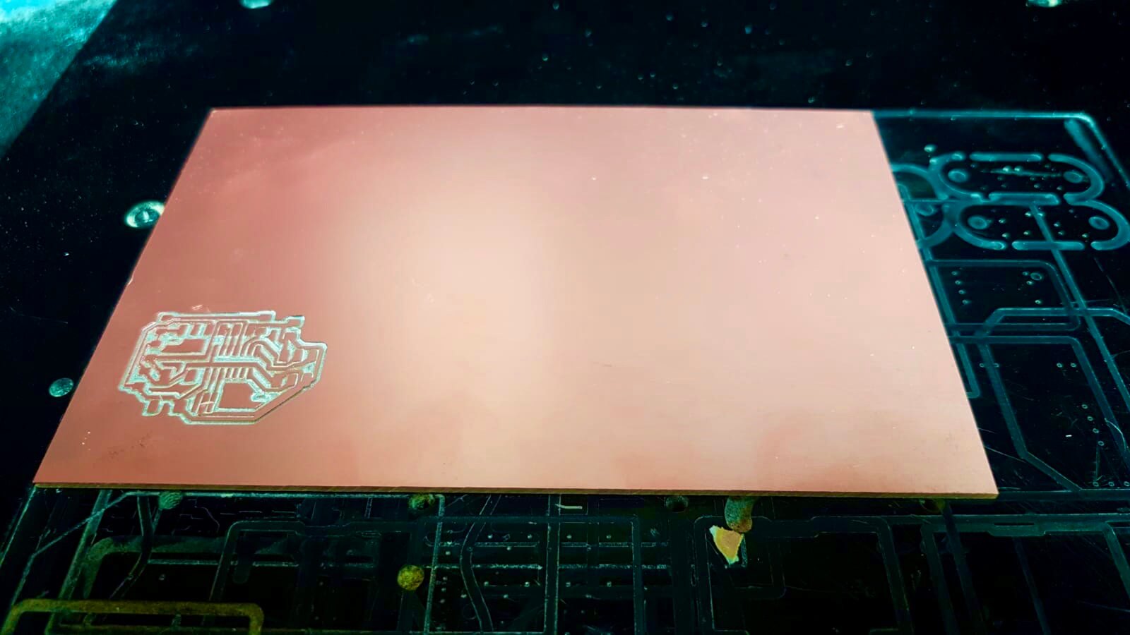
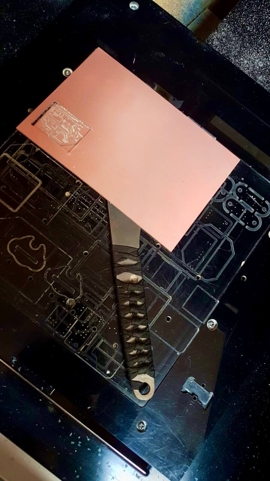
Once the cut is finished, we clean our card from the cut residues with a brush, broom, etc... and then we proceed to lift and then detach our card from the base; to do this we use the appropriate knife.
|
|
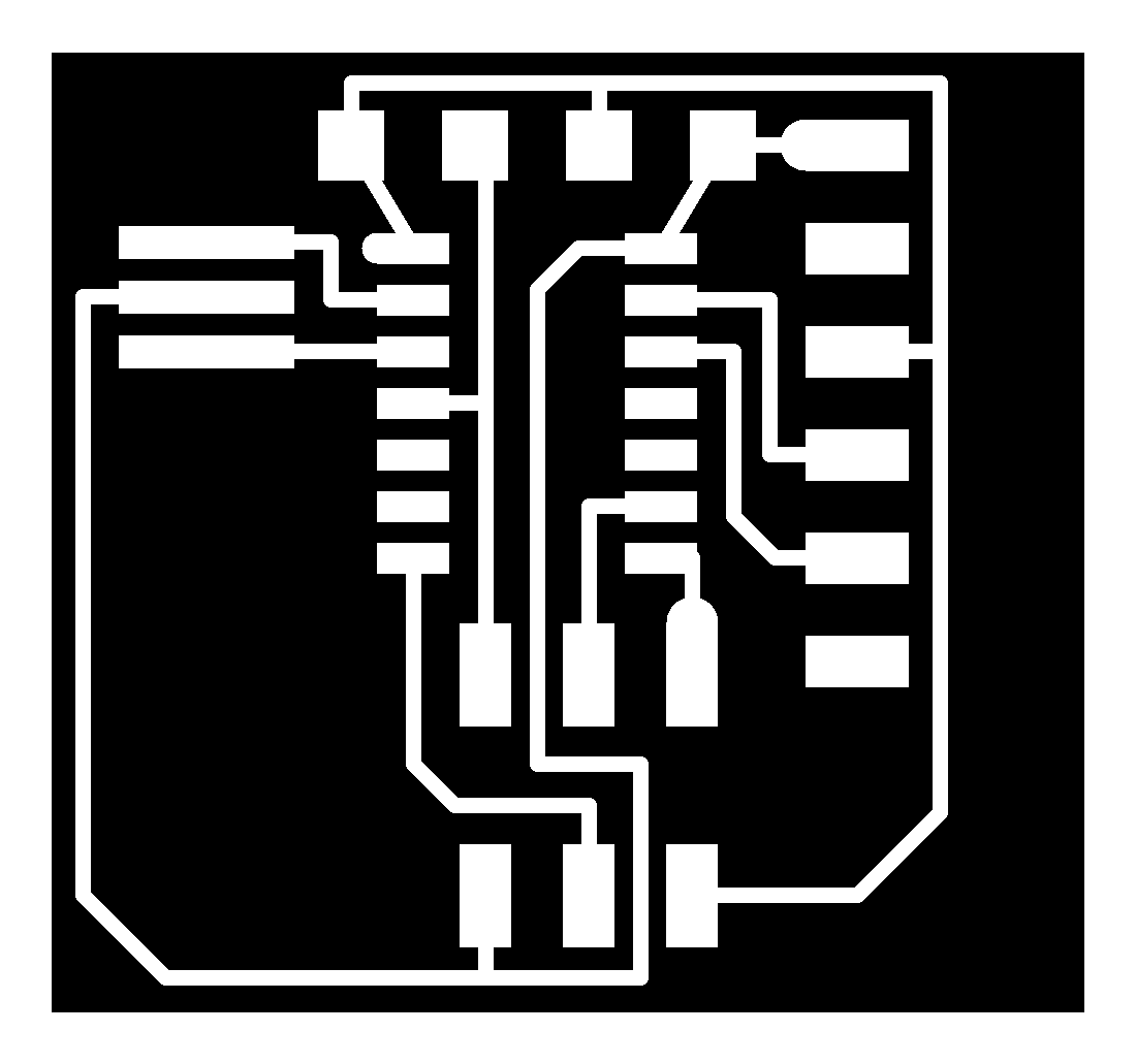
- TRACES_ROLAND
- BOARD_EAGLE
- SCHEMATIC_EAGLE
- OUTLINE_PNG
- TRACES_PNG
GROUP ASSIGNMENT
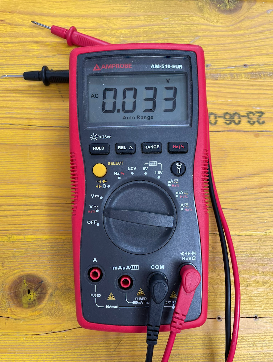
To complete this assignment, we used the digital multimeter, even called tester, we have in the lab Amprorobe AM-510-EUR and measured the voltage in the elements of a board.
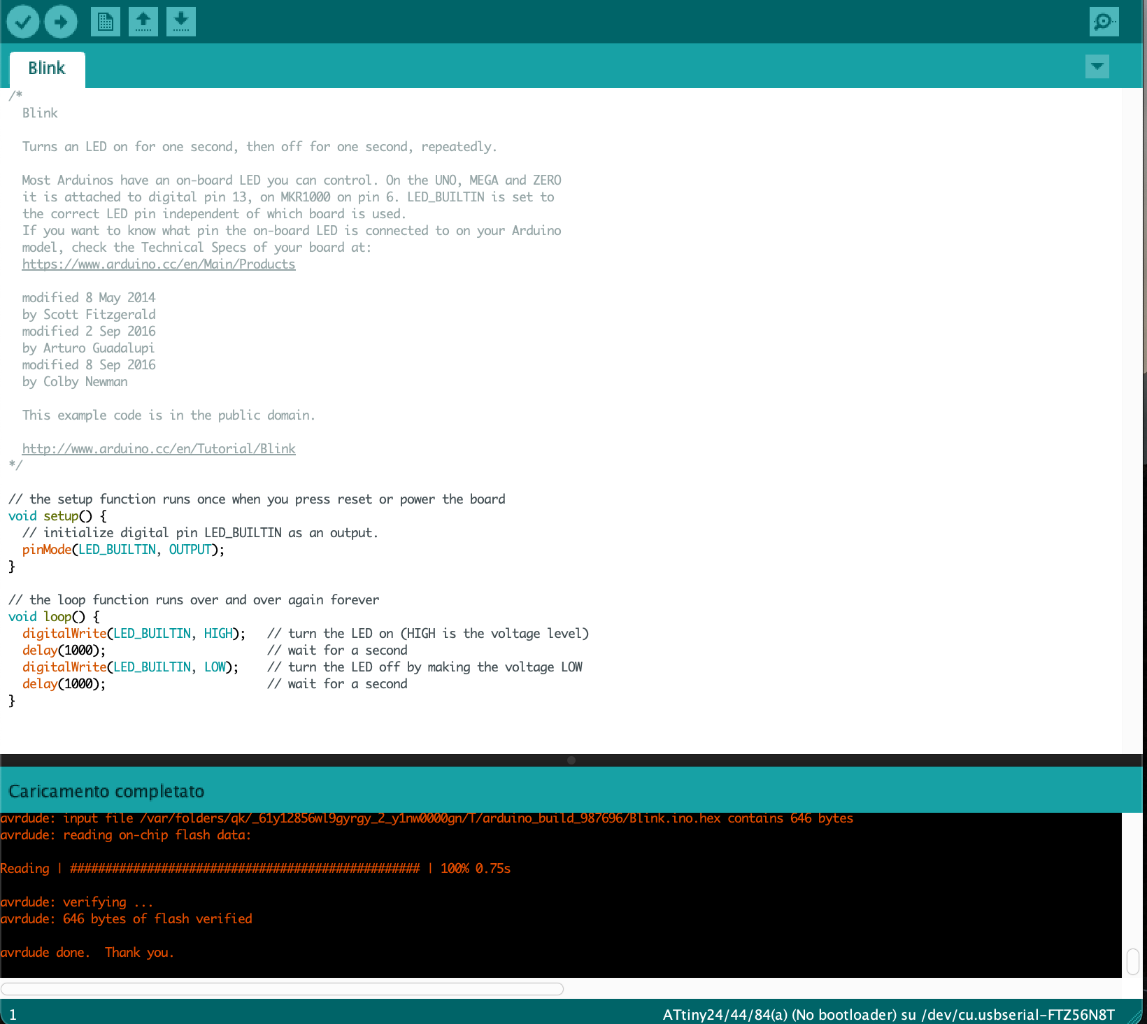
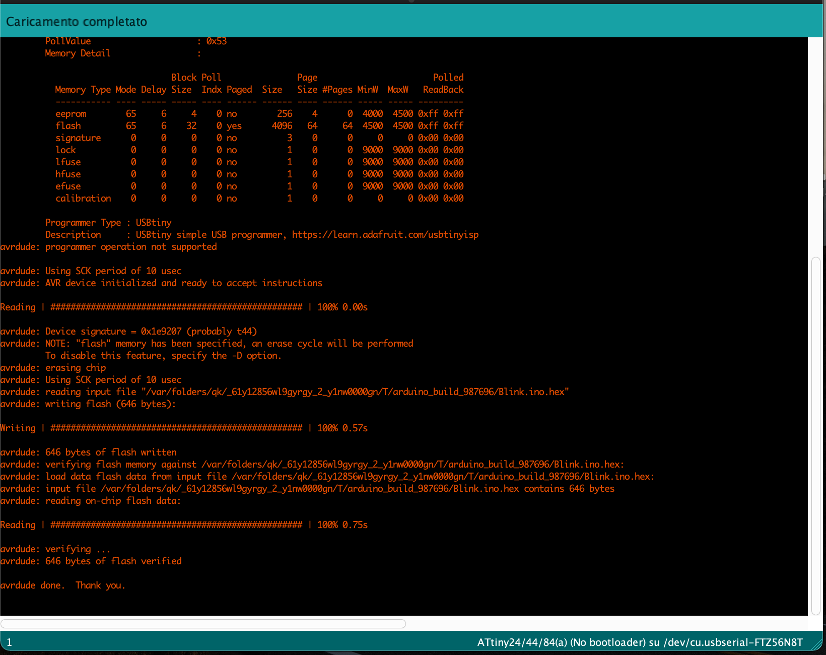
First of all, we have loaded the blink program which makes the led of the board blink.
In order to measure the voltage drop of a component in the optimal way, the tool with which we are going to measure it must be placed parallel to it.
Rotating the wheel of selection, we selected the option to measure DC voltage. And we measure the voltage drop in the LED and also in the resistance that is connected in series with the LED. The sum of both must be equal to 5v (voltage of the output pins of the microcontroller).
Accessing to the continuous current function and selecting the acoustic signal mode, we can use the continuity signal function that allows to test the quality of the electrical current flow on the PCB.
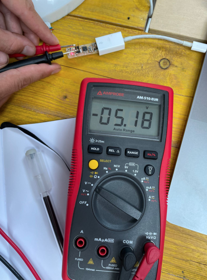
We used the multimeter to detect the amount of current on the PCB circuit in Volt. The result was 5.18, so it is coherent to what we expected.
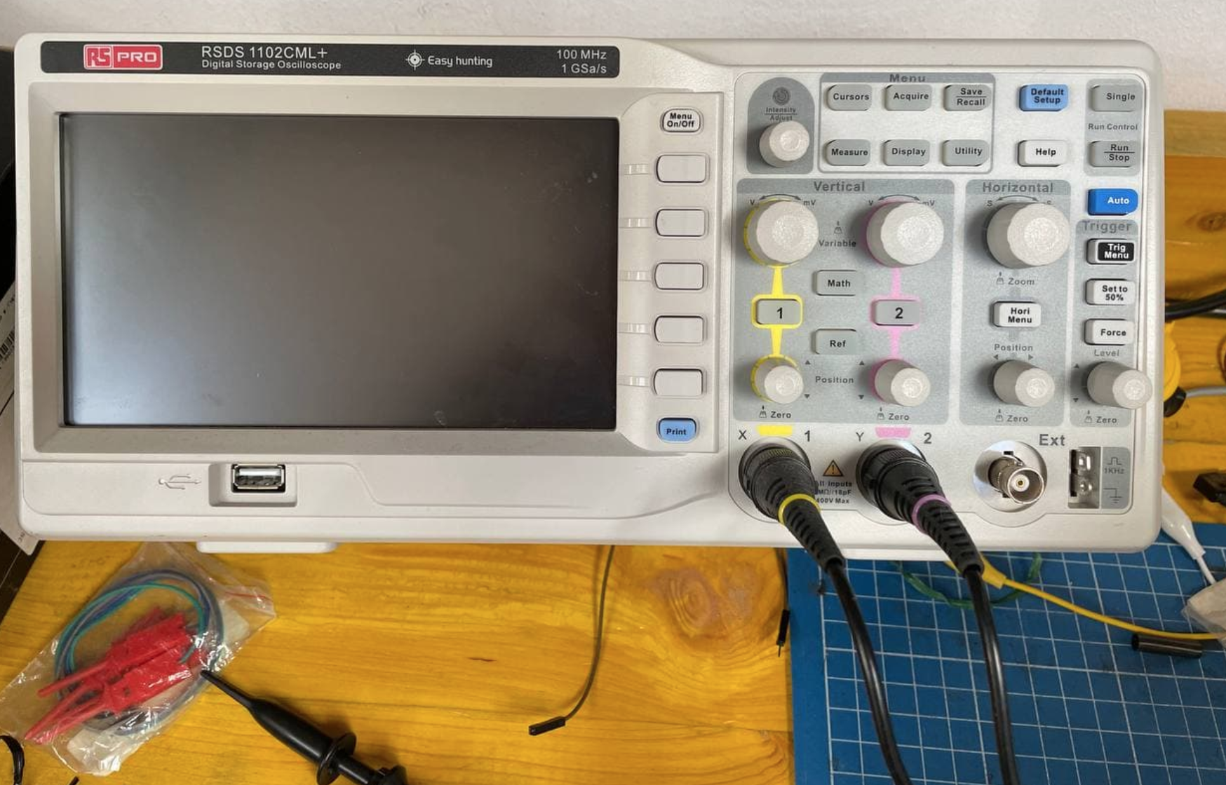
This is the oscilloscope we have at Opendot, a RSDS 1102CML+ Digital Storage Oscilloscope. It gives qualitative measures on code wave signal movements , since the electrical current is invisible it’s very important to visualize how the electrical current passes though the circuit. It’s like a multimeter with a display, allowing to visualize how the signal is moving.
The oscilloscope we have in OpenDot, a RSDS 1102CML+ Digital Storage Oscilloscope, has a digital monitor display. The ray of electrons coming from the signals trace the lines on the monitor.
The horizontal lines of the squares represent time and the vertical ones the tension, so the graph displays the tension passing through the circuit in time.
In the buttons of the oscilloscope there is a wheel that sets the volts by division, and it’s possible to change the position of the signal moving the Y wheel of the oscilloscope using the AC mode, while the OC mode stays on the 0 level of the monitor.