Mechanical and Machine Design
ASSIGNMENT
Group assignment
- Design a machine that includes mechanism+actuation+automation
- Build the mechanical parts and operate it manually
- Actuate and automate your machine
INTRODUCION
For the Group assignment I am in a group with Filippo Moia.
WORK FLOW
Inspired by an old cartoon (Willy and the coyote) we thought of reproducing the cannon that the coyote used to try to capture Willy.

First of all, we studied how to integrate the movements of the cannon's X - Y - Z axes and therefore what movements we wanted our cannon to make and what we needed to make it work.
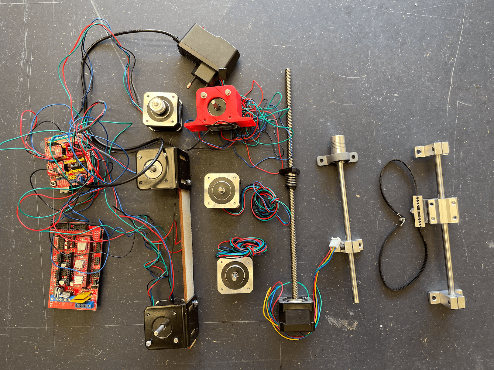
We have distinguished the two types of materials we need:
MECHANICAL PART
- rods for "X-Y-Z" axes
AUTOMATION - 1 servo motor
- 2 stepper motors
- CNC - Shield for Arduino
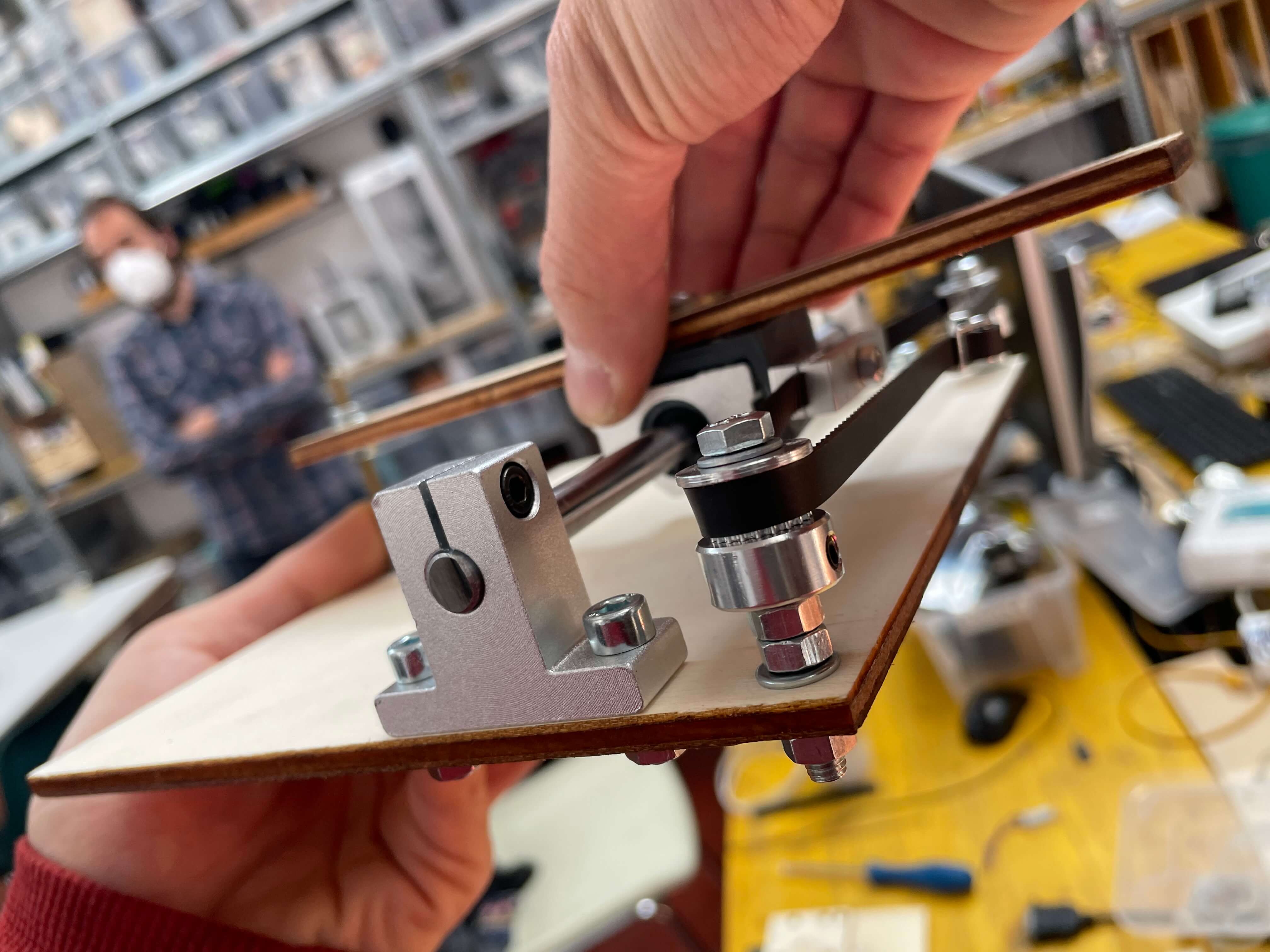
After finding all the parts we needed, we started to think about how best to convert linear motion into rotary motion.
To do this, we researched and then did some tests using Laser Cut to create circular and rectangular shapes in order to "study" rotary motion in detail based on our design idea.
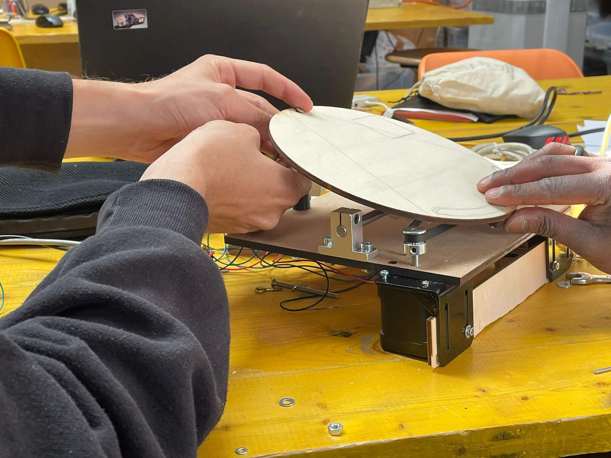
With all the material in hand, we started to assemble each piece so that we could see the volume and footprint of the machinery and then work out what size to make our external structure.
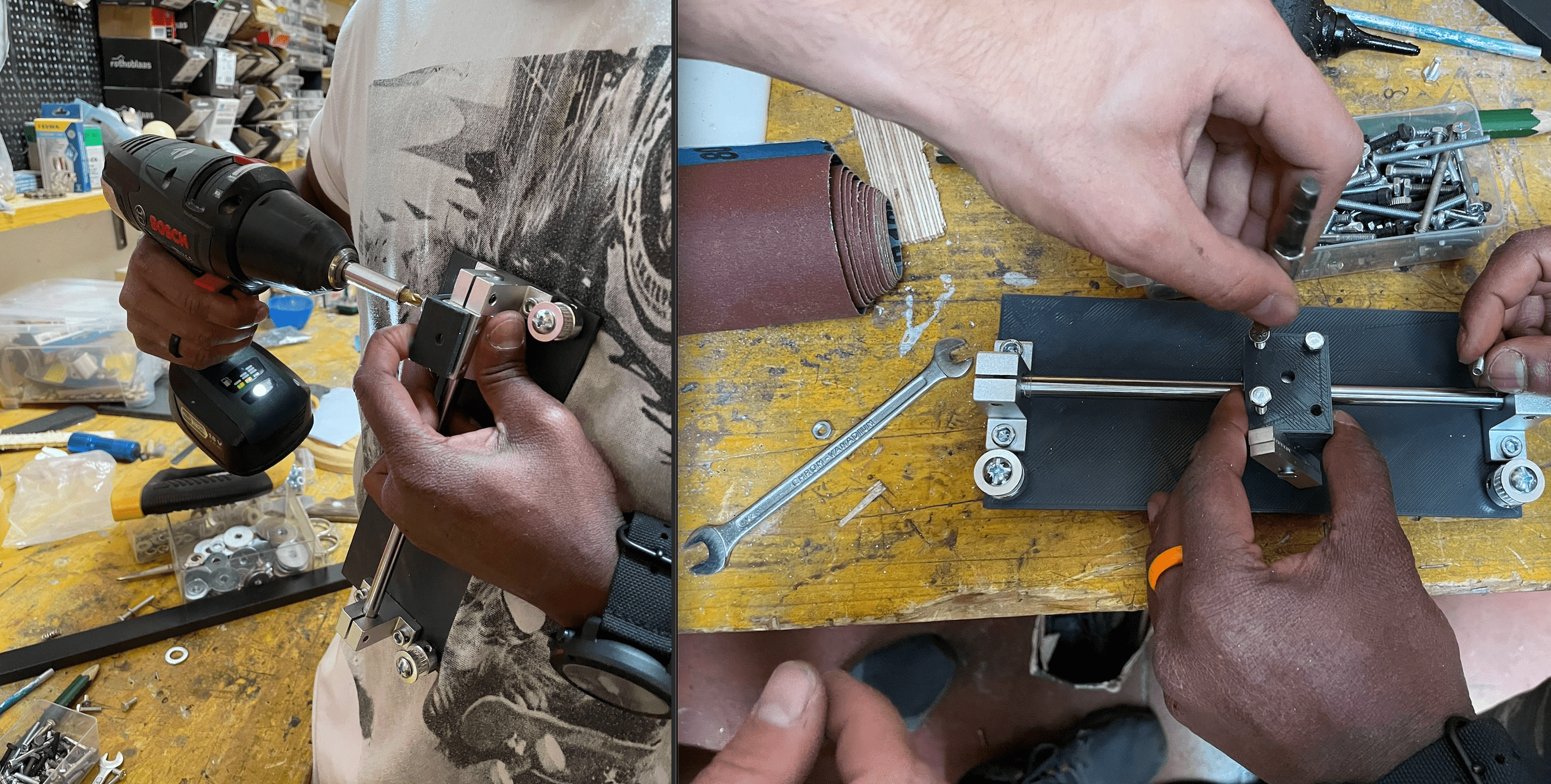
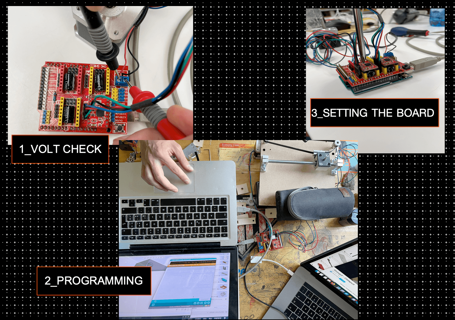
After that, however, we need to attach it to a stepper motor which we then programmed by attaching it to the Arduino Shield.
WHAT IS THE ARDUINO SHIELD ?
The Shield allows the Arduino to control 6 users via relays and to acquire the status of 6 analogue and 6 digital inputs and relay outputs. The board is powered directly by the Arduino module, which supplies the 5 volts from its regulator between the 5V and GND contacts. The Shield's mini-relays operate at 12 volts, so in order for the relays to work properly you need to power the Arduino module with an external power supply capable of providing this voltage. Obviously we will use this type of board to control our motors, but it can be used in many different ways.
Now that the engine is running and the base of our cannon is spinning, we need to create the cannon. To do this we will take all the necessary measurements and then we will design it on Autodesk Fusion 360 and 3D print it. On top of that we're going to print some supports attached to the outside of the cannon so we can attach the engines to it and also the base for our mechanical parts.
- SPACER
- Z_JOINT
- CANNON
- CANNON TOUCHING BUILDPLATE
- JOINT FINAL
- PILLOW FINAL
- PISTON
- PISTON FINAL
- SHAFT FINAL