Electronics Production
Principles and Practices, Project Management
ASSIGNMENT
Individual Assignemnt
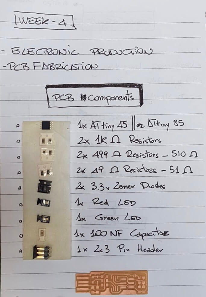
make an in-circuit programmer by milling the PCB, then optionally trying other processes
Group assignment
characterize the specifications of your PCB production process
WORK FLOW
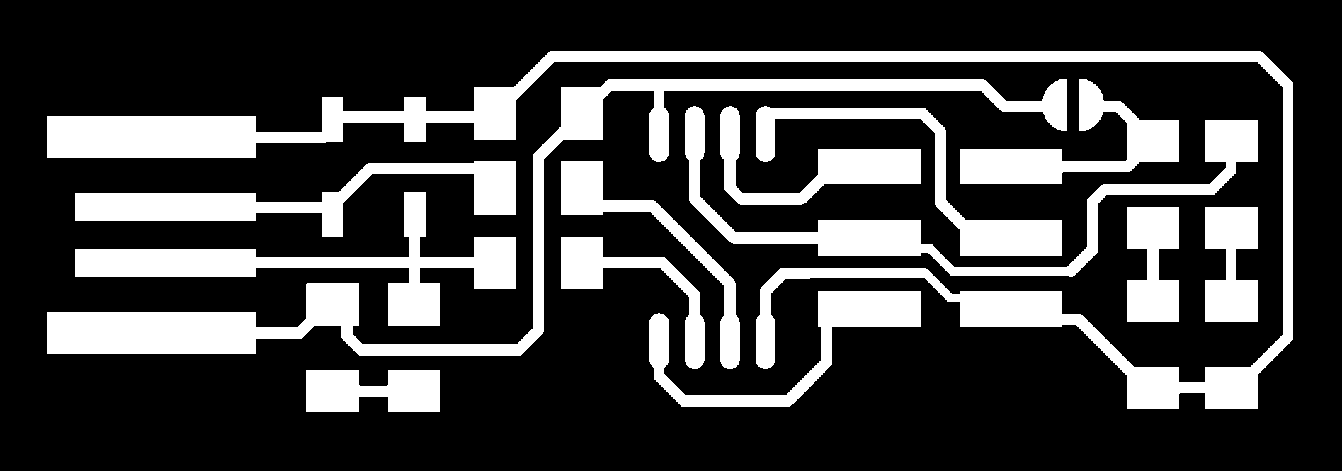
The first step to do is to download the basic FILE (FabTinyISP) that we can make readable and set for the machine through (FabModules)

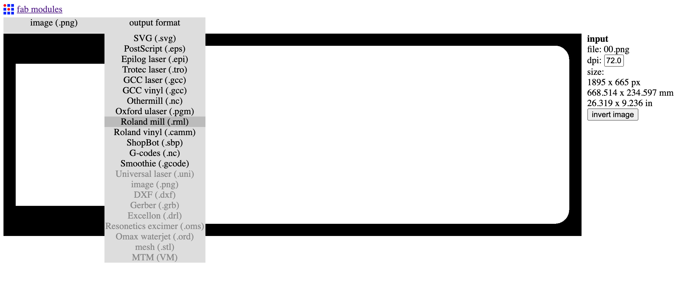
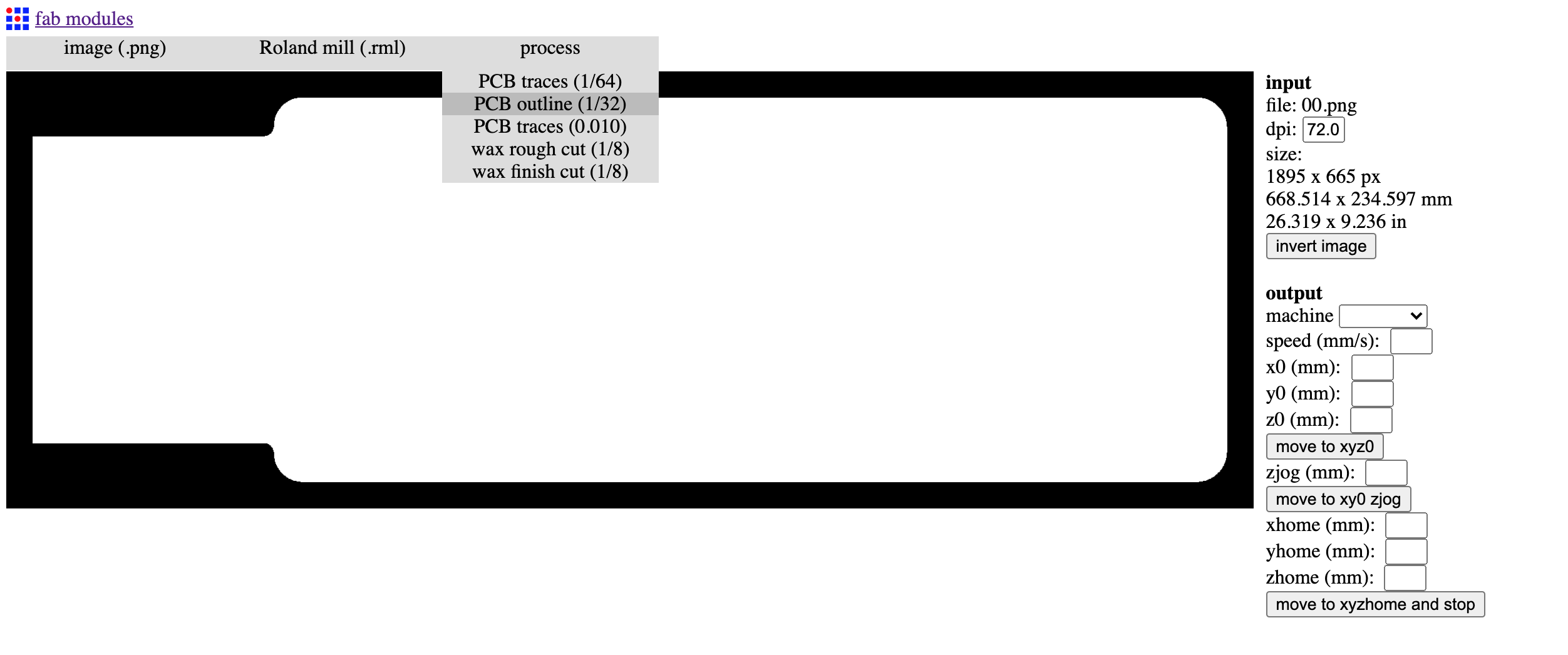
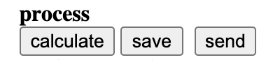
After setting the "PROCESS" will appear some parameters that we will have to complete with the values we need:
- OUTPUT machine
- indicate which machine we will use (MDX-40)
- x0 (mm): we indicate the origin point of X (length) - we reset it and index it at the time of cutting;
- y0 (mm): Enter the origin point of Y (width) - reset and index at the time of cutting;
- z0 (mm): Enter the origin point of Z (depth) - reset and index at the time of cutting;
|
|
|
|
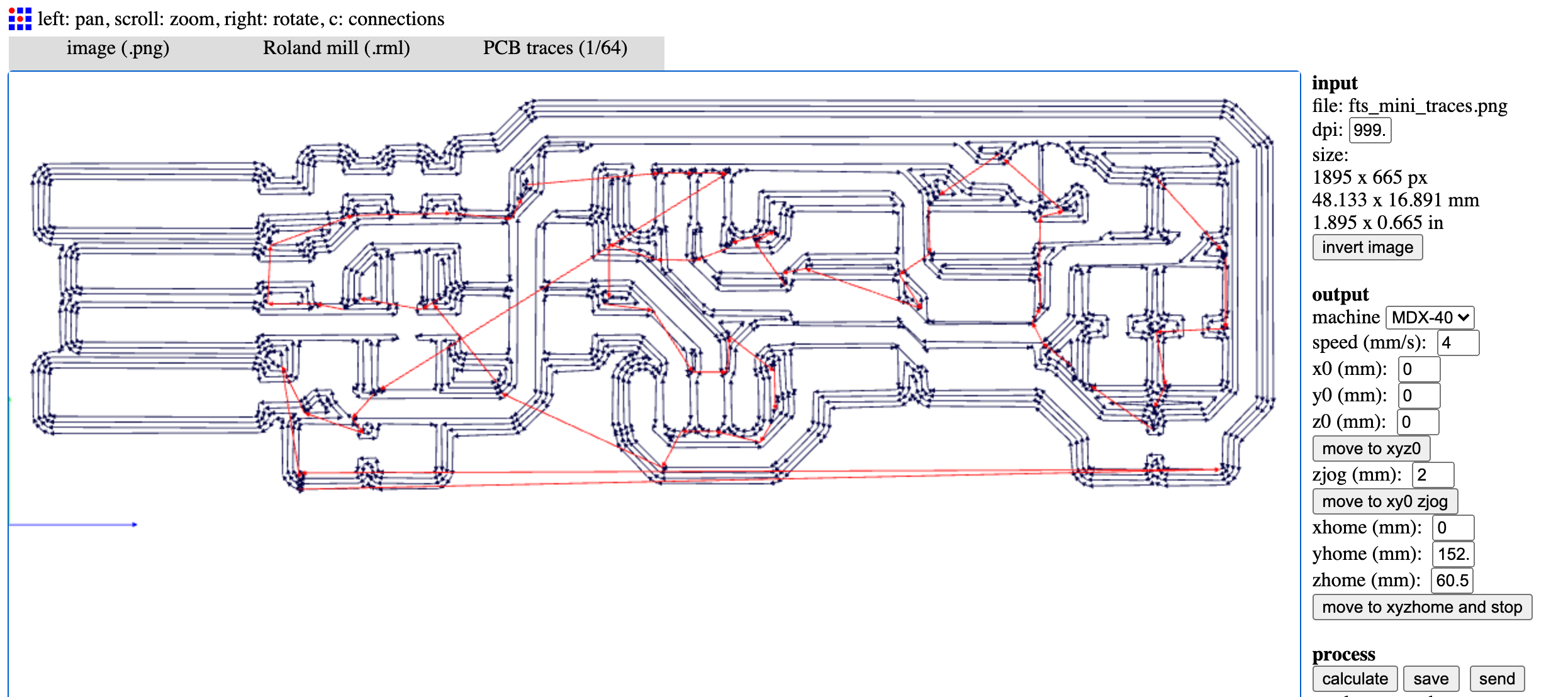
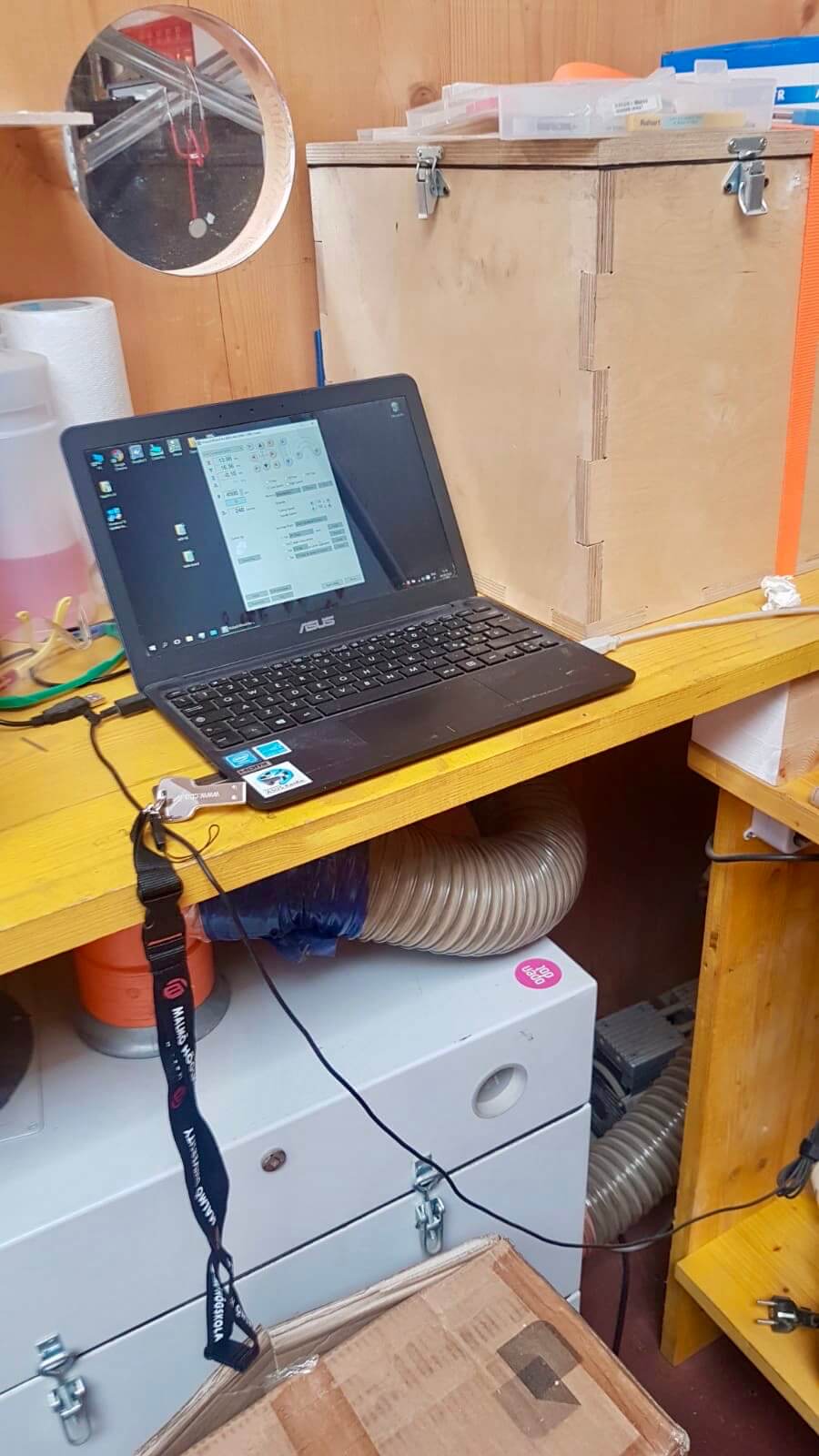
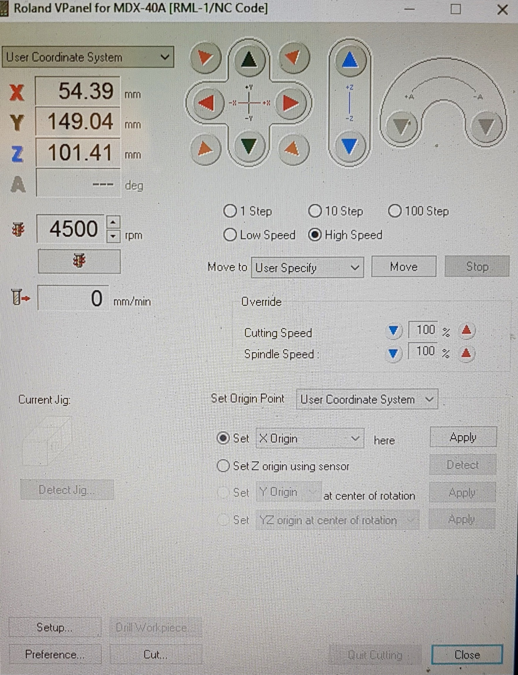
Once this is done, I enter the program of the machine called V-Panel and set the origin of X-Y-Z with these simple operations:
- X-Y Origin: with respect to what I have to cut and where (referring to the PCB "plate") I move down to the bottom left which will be the beginning of my cut;
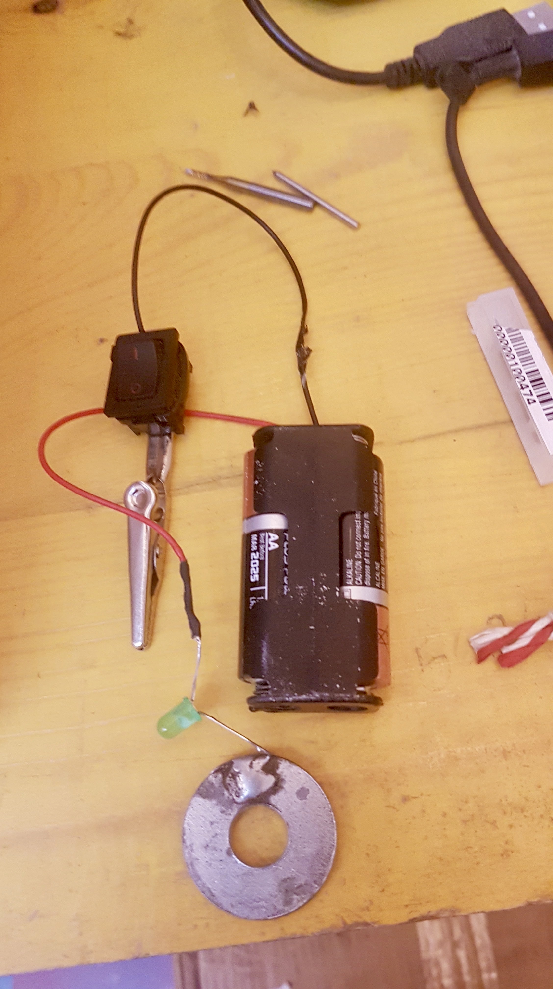
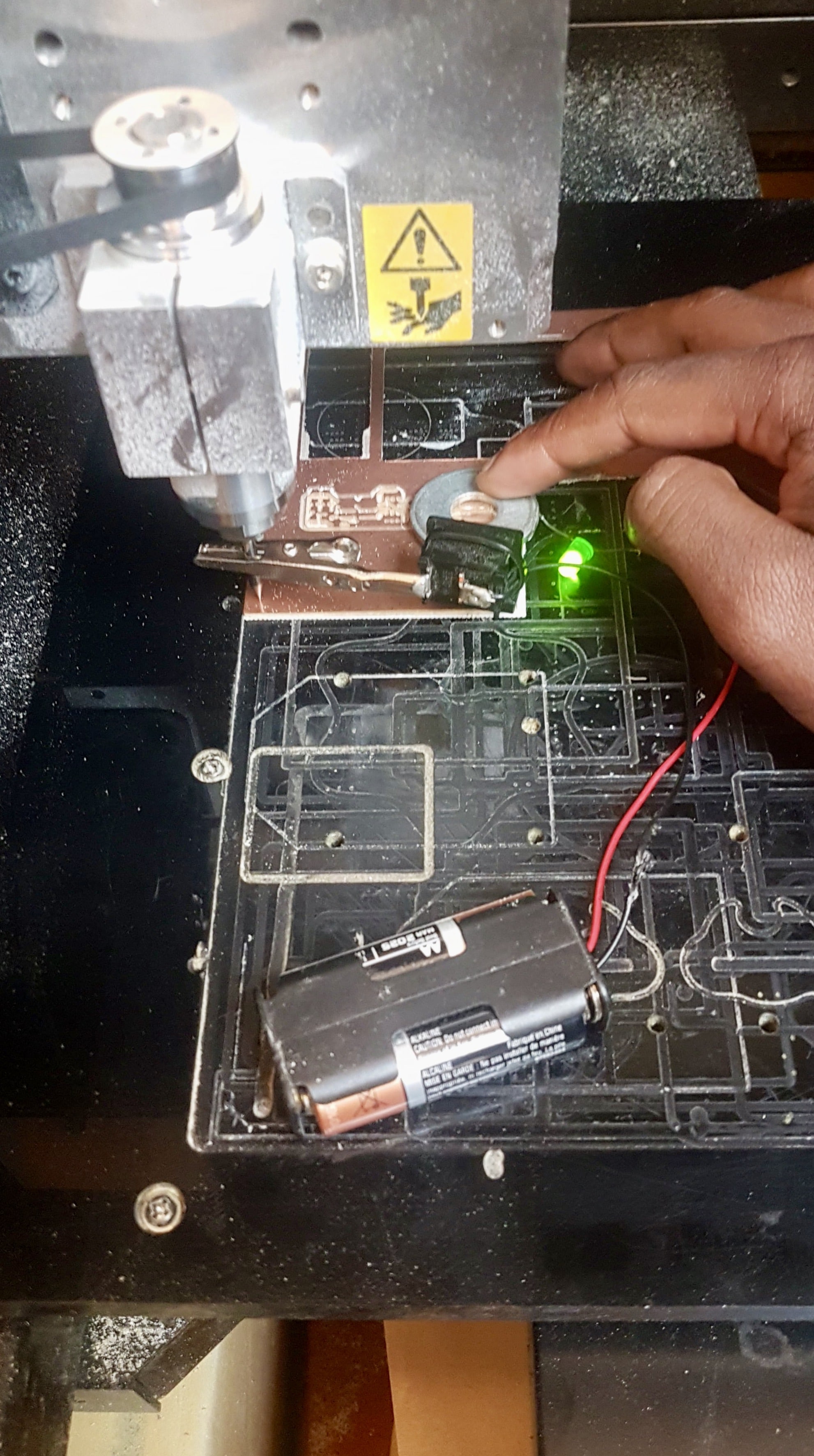
- Z Origin: to find its origin I have an electronic device designed here in Fab-Lab that allows me to understand when the tip of the machine touches my PCB board. You attach the tweezers to the tip, then turn on the switch and place the washer on our PCB board and operate manually so that the whole washer rests on the board;
|
|
|
|
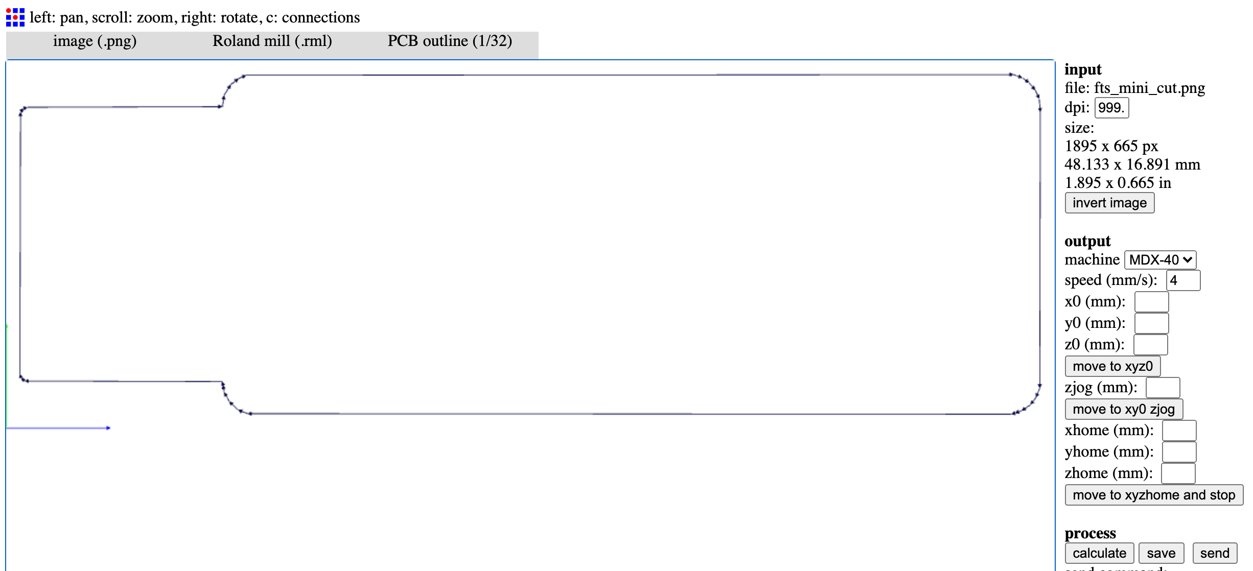
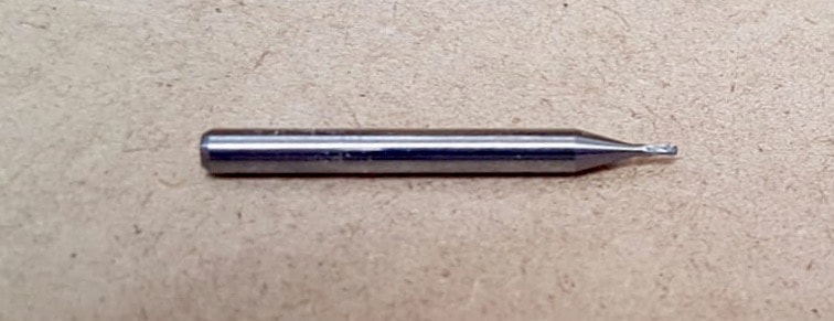
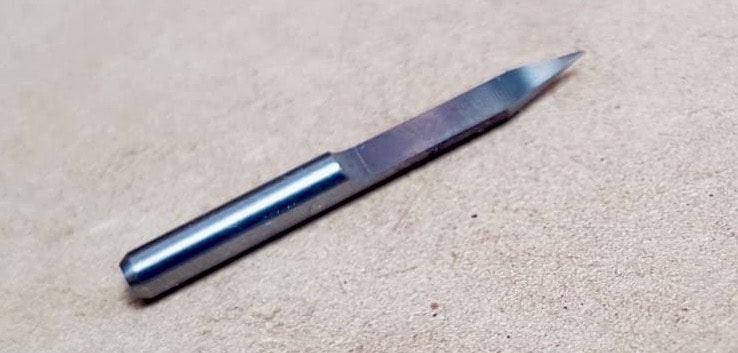
The tip for the inside, the TRACES, is a 1/2 "V" shaped tip which allows it to mill even the most attached parts, but in any case there is obviously a cutting margin beyond which the tip cannot reach.
IMPORTANT !
It is very important to check that the TRACES bit is always sharp and not broken, otherwise it will not cut properly. .To get these types of tips there is no single link, there are many, for example:
(DIGIKEY) (ALIBABA) (PCB FACILE)
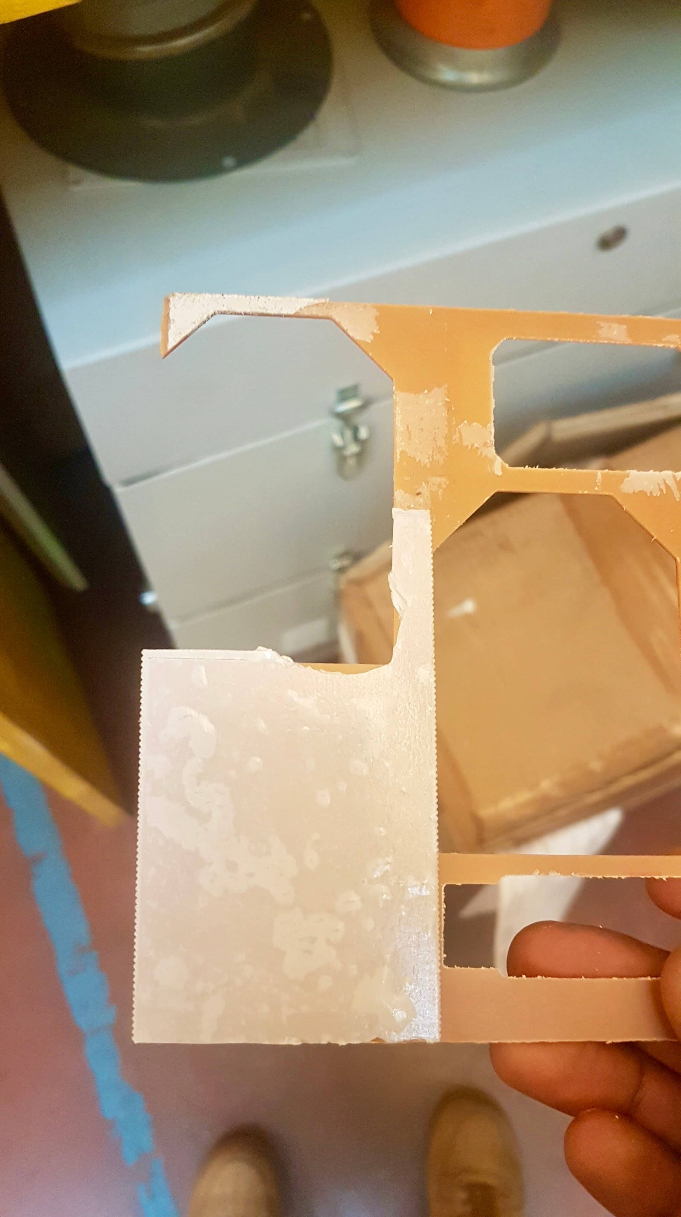
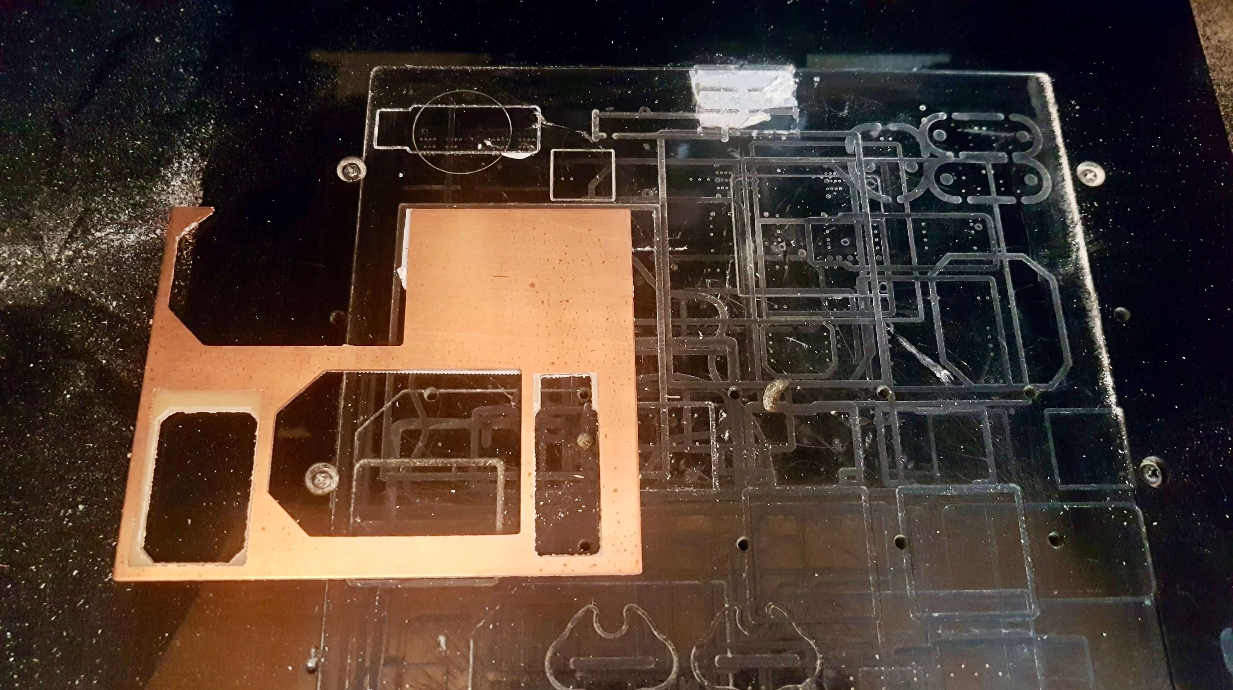
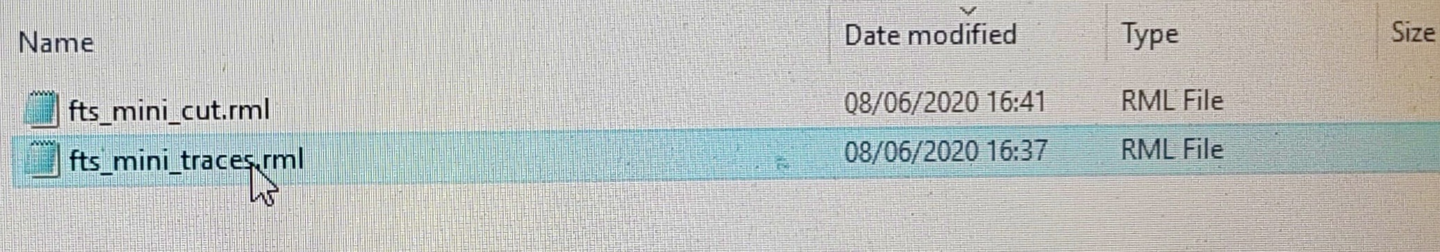
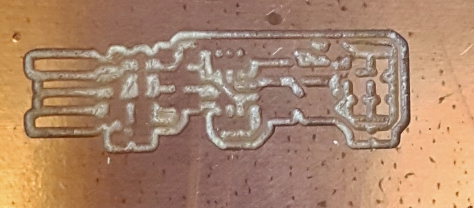
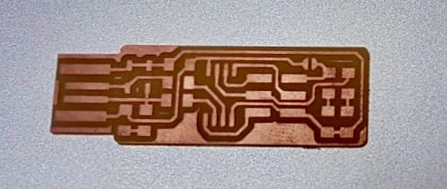
During the processing I made a mistake and in the program (fab-module) I set 1/32 also for the "traces" file: doing so the tip dug too deep, making my PCB unusable, even if I must admit that aesthetically it is very artistic (hahahah).
I reset my "traces" file so that it is 1/64: this time the result is correct and you can see the clear difference between the wrong and the right one.
|
|
|
|
- TRACES
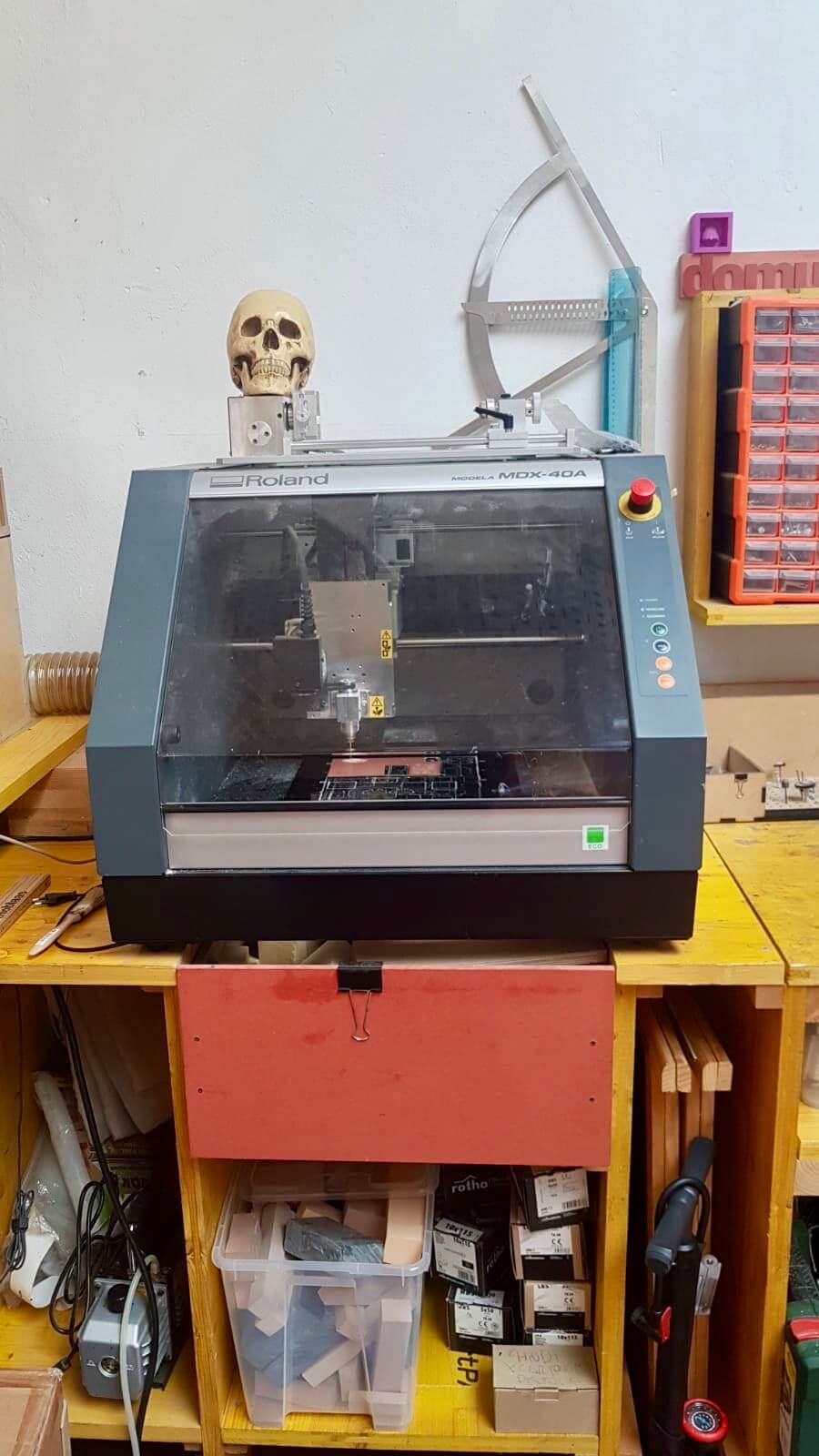
SOMETHING ABOUT THE MACHINE
this is the link where you can find all the information about the machine and the supplier (LINK)
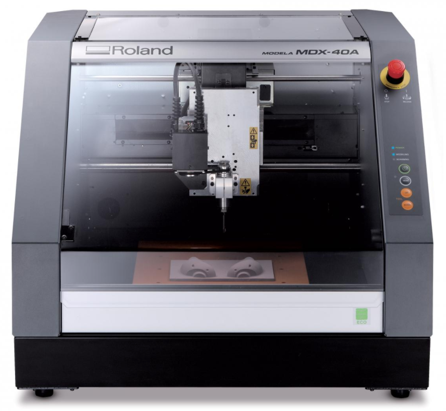
The MDX-40A and the CAM SRP Player
The MDX-40A milling machine can handle both data input and output thanks to the fact that it can not only model but also scan the object to be reproduced. In addition to the prototyping part, the MDX-40A is equipped with a contact scanning probe that can be installed on the machine spindle. The ZSC-1 probe allows the surfaces on the work table to be scanned with centesimal resolution. The file is then managed by the software supplied with the probe. The MDX-40A comes complete with a software suite for managing both milling and scanning.
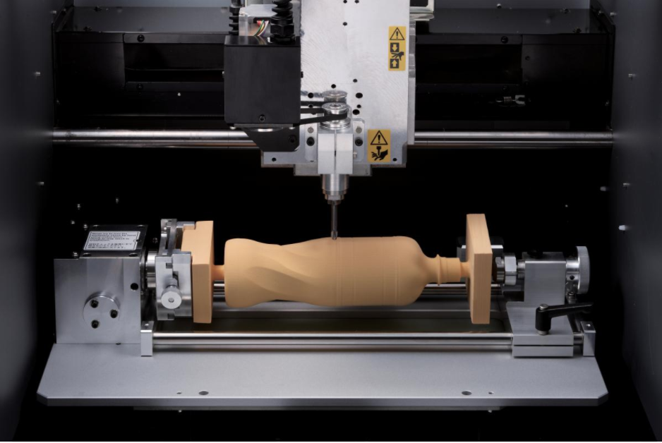
4th rotary axis (optional)
With its dedicated rotary axis, the MDX-40A performs automatic two-sided and four-sided machining. Once one side is completed, the part is automatically rotated until all four faces are finished. This feature reduces errors associated with manual handling and provides significant time savings in addition to all-round machining. With the fourth axis ZCL-40A, the working area increases significantly and allows four times the overall volume of the previous series, with a maximum weight on the axis of 1kg. This makes it possible to work on material with a diameter of 120 mm and a length of 270 mm, such as, for example, the prototype of a 500 ml plastic bottle.
SRP technique for modelling with MDX-40A
The SRP technique, a feature of all Roland modelling machines, has several advantages over additive synthesis. SRP technology is much more competitively priced and allows the use of different types of modelling material, with high precision on axis movement and better quality of finish and detail.
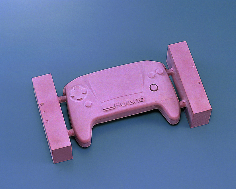
Versatility
The Roland MDX-40A can machine a wide range of materials such as ABS, waxes, resins, chemical wood, acrylics, PVC, POM, wood, etc. This allows designers to create functional prototypes for application and working tests with significant time and cost savings. In fact, the prototypes can be tested and tried out before the final product is manufactured to assess their quality and functionality. The working area is 305 x 305 x 105 mm (without 4th axis installed).
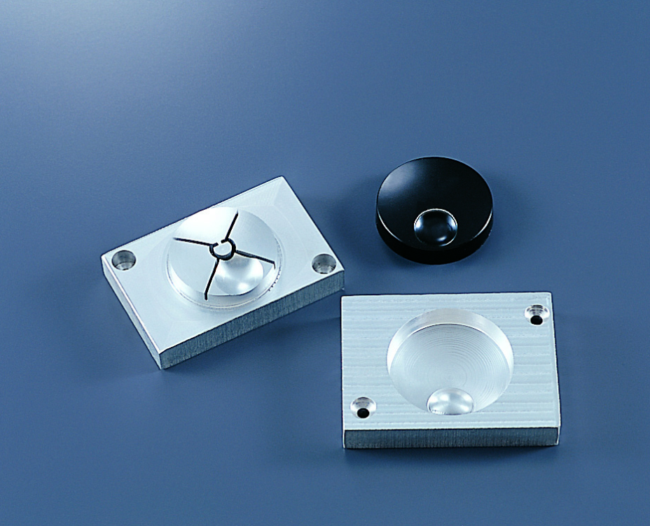
Precision and accuracy
The MDX-40A is equipped with a high-precision spindle with a clear reduction of vibrations and a consequently high quality of part manufacturing. The mechanical working resolution is 0.002 mm/step, allowing accurate part production. The spindle mounts standard ISO15448 collets and the resulting finishes require no further machining. The spindle motor has a power of 100 W and a variable speed of 4500 to 15000 rpm.
MDX-40A: Surface scanning
Thanks to the ZSC-1 scanning probe, it is possible to transform the MDX-40A into a three-dimensional contact scanner with centesimal resolution. All this is driven directly by the software supplied with the probe, Dr.Picza3 and 3D Editor, which allow you to act on the scanned surface. The manageable scanning area is 305 x 305 x 60 mm and the scanning resolution is 10 microns. The scanning quality is really good, with smooth and very detailed surfaces. The scanning phases proceed automatically and therefore operations take place without the need for an operator. Installation of the scanning probe is quick and easy. The workpiece can be stopped using the wax provided. Surface detection is carried out on all three axes X, Y and Z. The resulting files can be commonly exported to the most common formats for 3D CAD and computer graphics software.
For every working environment
Thanks to its compact design, the MDX-40A can be easily placed in a wide range of environments, from design studios to technical offices as well as production workshops. The MDX-40A is equipped with an emergency stop switch and a safety cover that makes the worktable inaccessible during milling and prevents machining waste from escaping from the machine.
Software Included
Roland shapers come with a software suite that allows the operator to start working immediately without any additional software.
Group Assignment
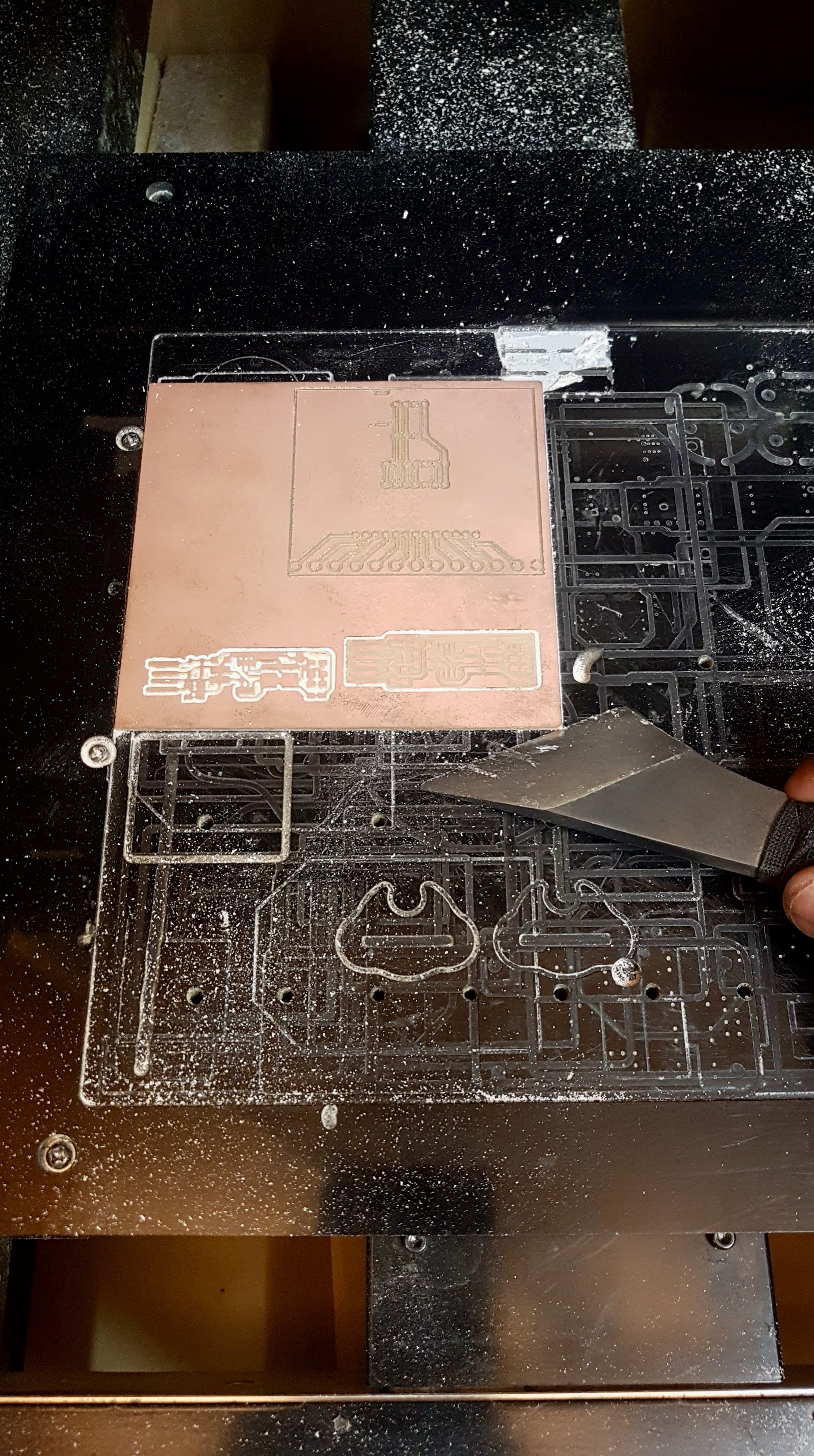
We mainly use our loyal Roland MDX-40 in order to mill circuit boards. We also generally use FabModules to generate CAMs.
Our design rules are generally the following:
- minimum space between traces is 0.4mm, which is almost 16mil
- in order to engrave our phenolic paper we set the spindle RPMs to 15‘000
- we use a 0.1mm cut depth for the trace, only one stepdown is necessary
- we use instead a 0.6 cut depth for outlines, because the stock is 1.7mm thick, outline jobs take 3 stepdowns
- the speed is about 2mm\s for engraving
- this speed drops to 1mm\s for outline cutting
- sometimes is helpful to “trick” FabModules by slightly reducing the tool size (to 0.38 or 0.36), because sometimes the software does not recognise spaces in between parallel diagonal lines
- we use 0.2mm or 0.4mm 30° V-bits for the traces
- we use a 0.79mm flat mill end for outline cuts
Task list
-
[x] Characterized CNC machine
-
[x] Milled tests
-
[x] Milled Programmer boards
-
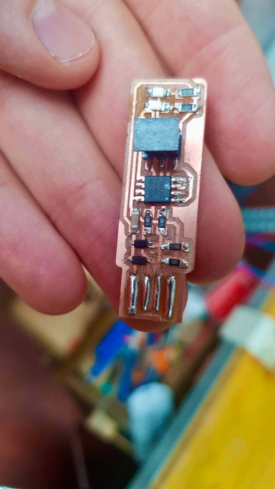
[x] Stuffed and soldered the board
-
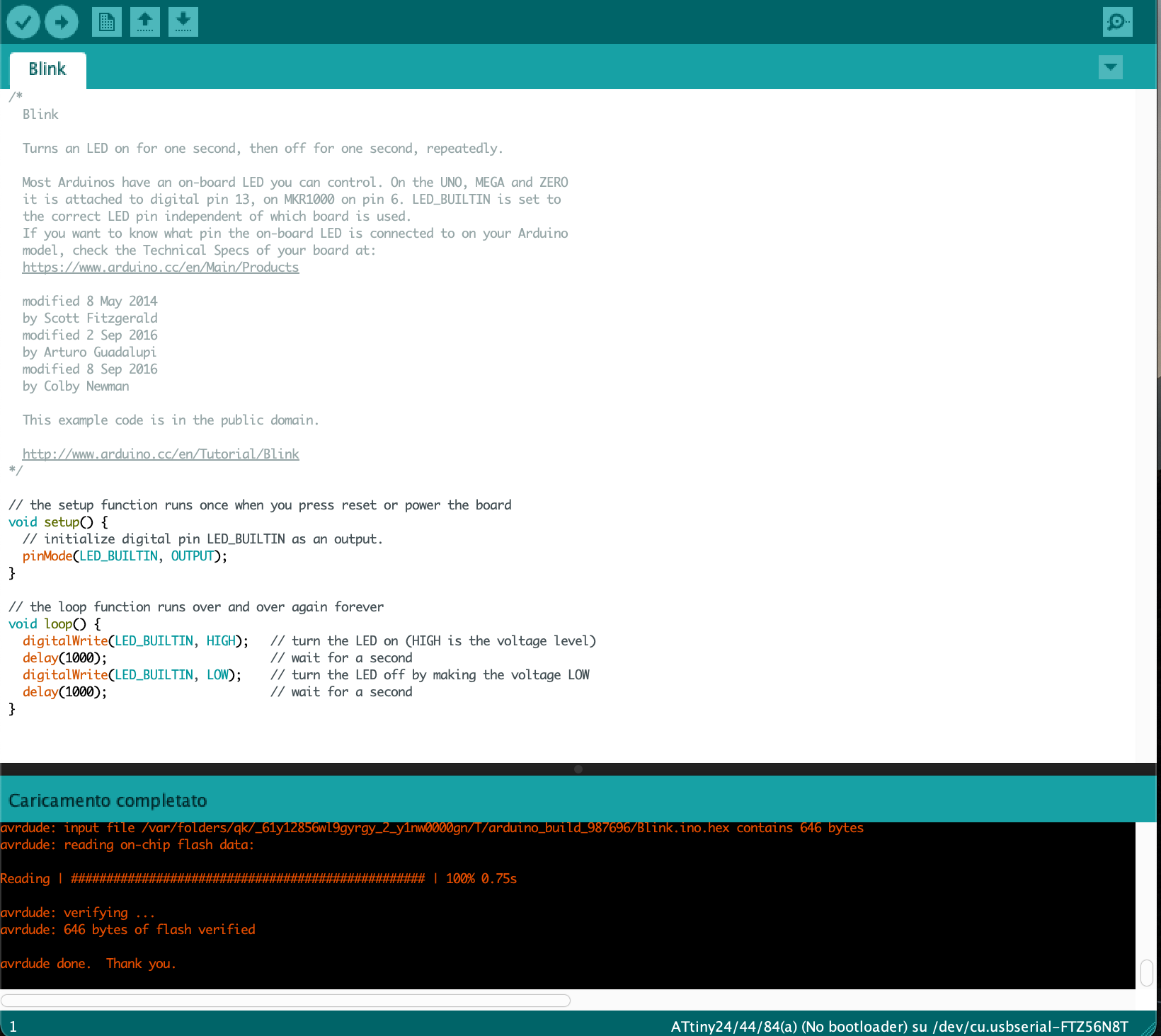
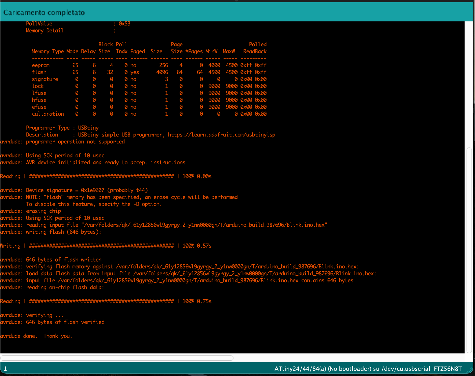
[x] Programmed the board
-
[x] Use the programmer to program another board