Output Devices
ASSIGNMENT
Measure something: add a sensor to a microcontroller board that you have designed and read it
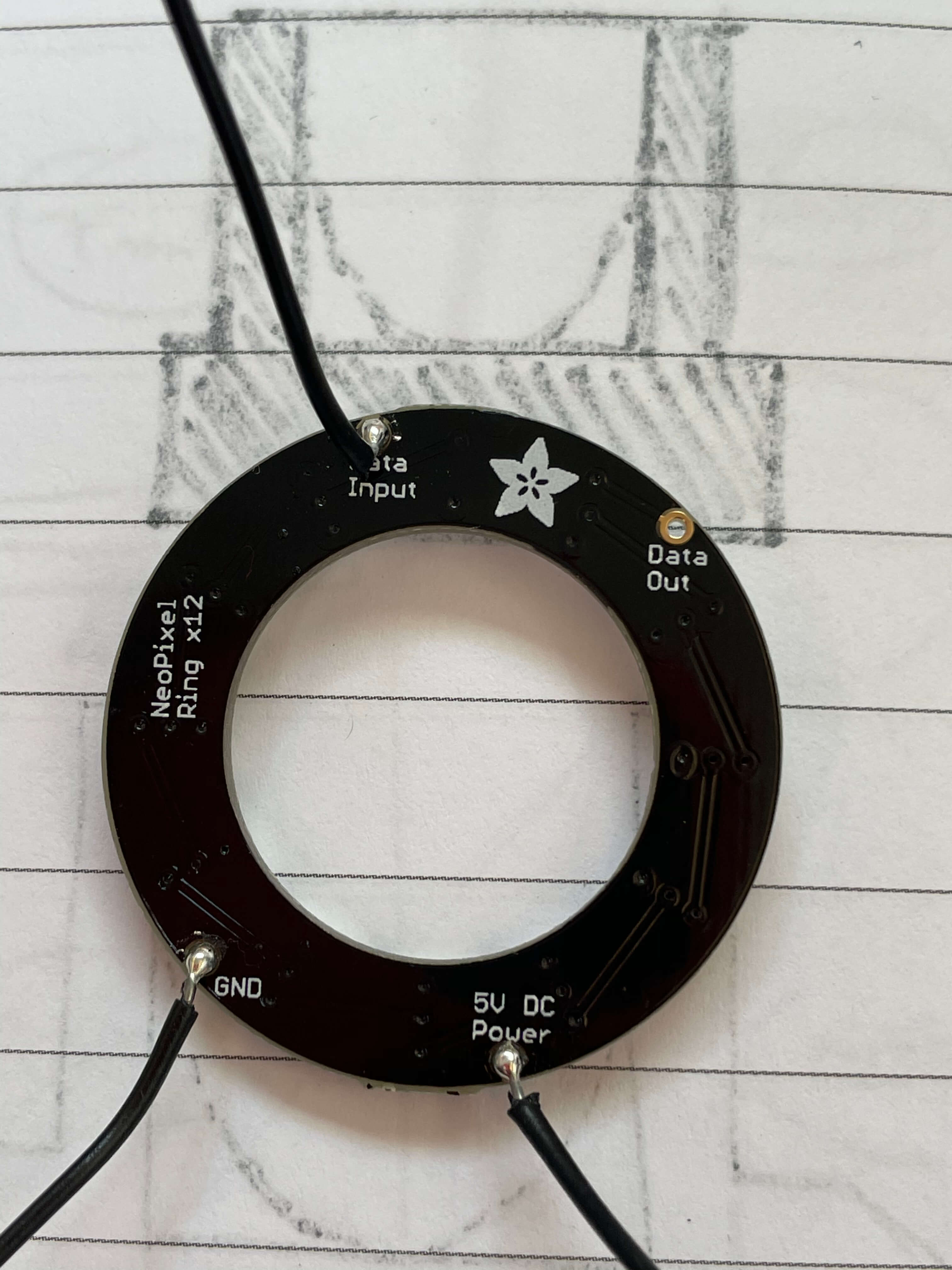
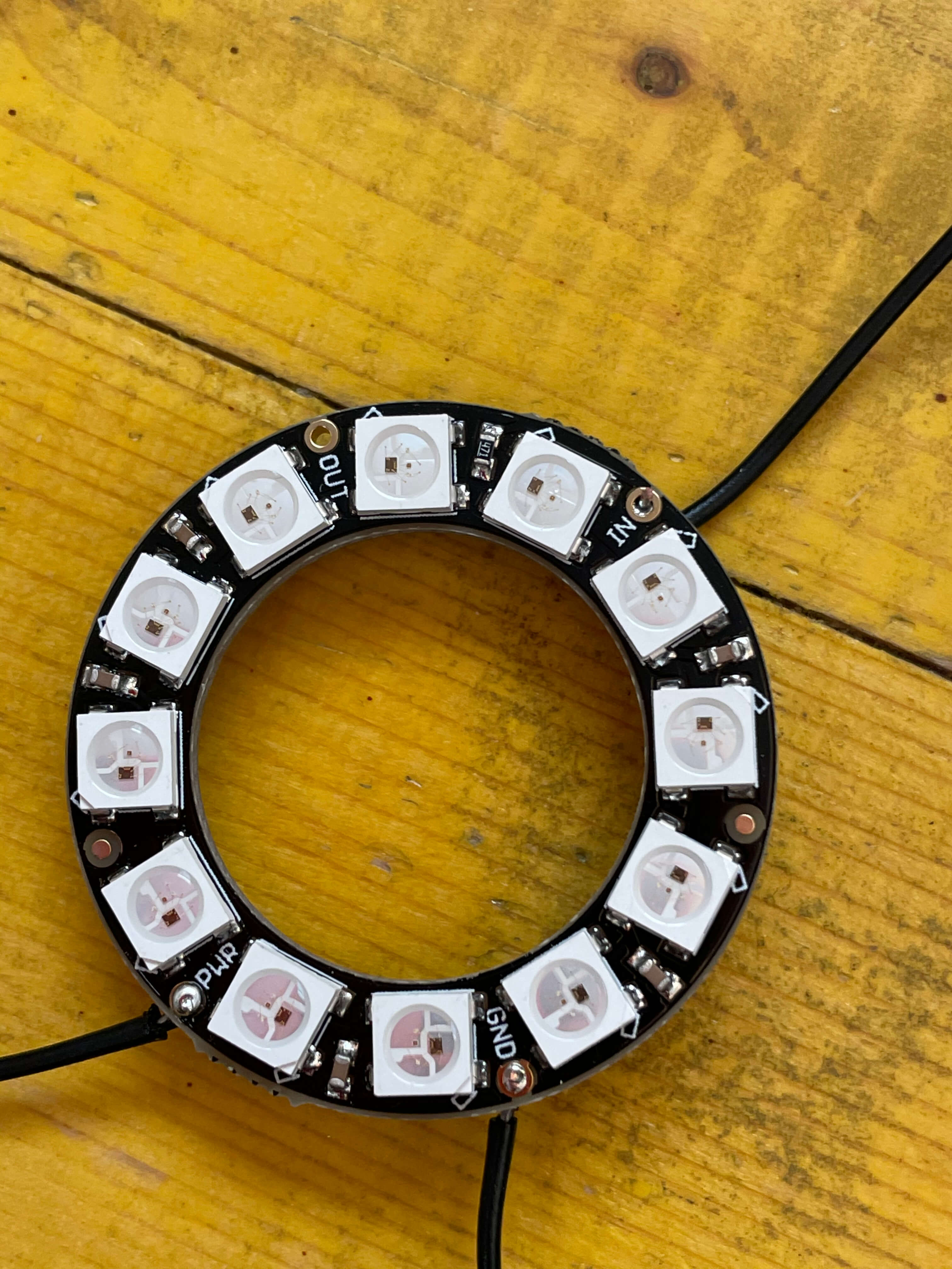
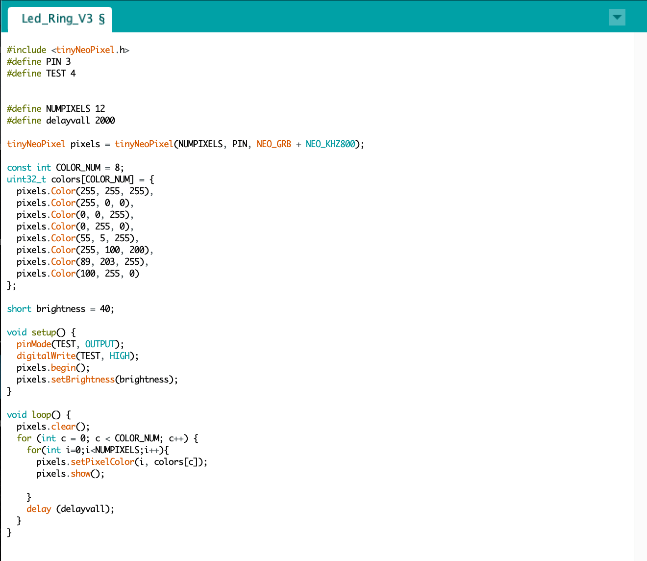
As OUTPUT DEVICES I have programmed a LedRing, the same LedRing that I will later need in my FinalProject (neopixel x12)
|
|
|
|
|
|
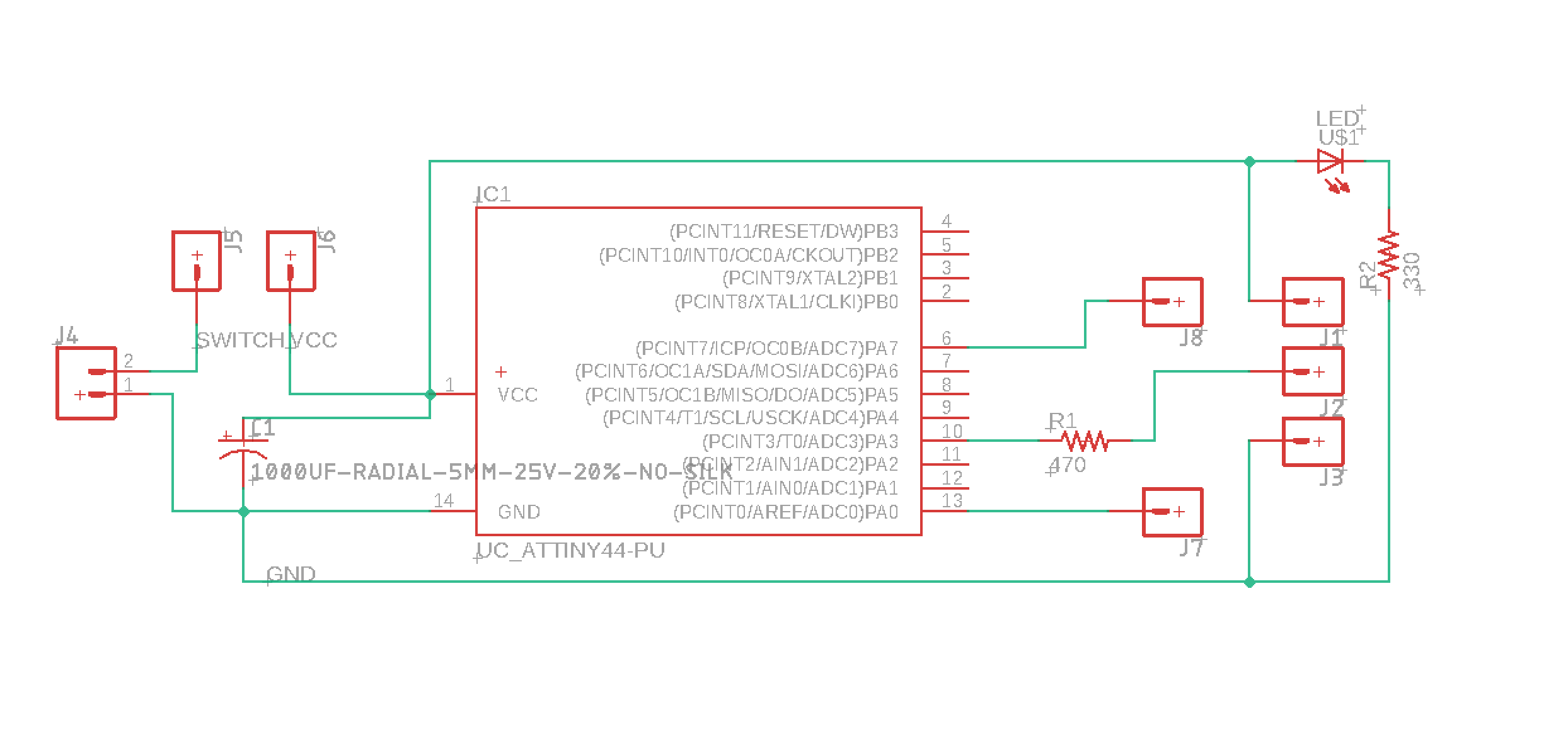
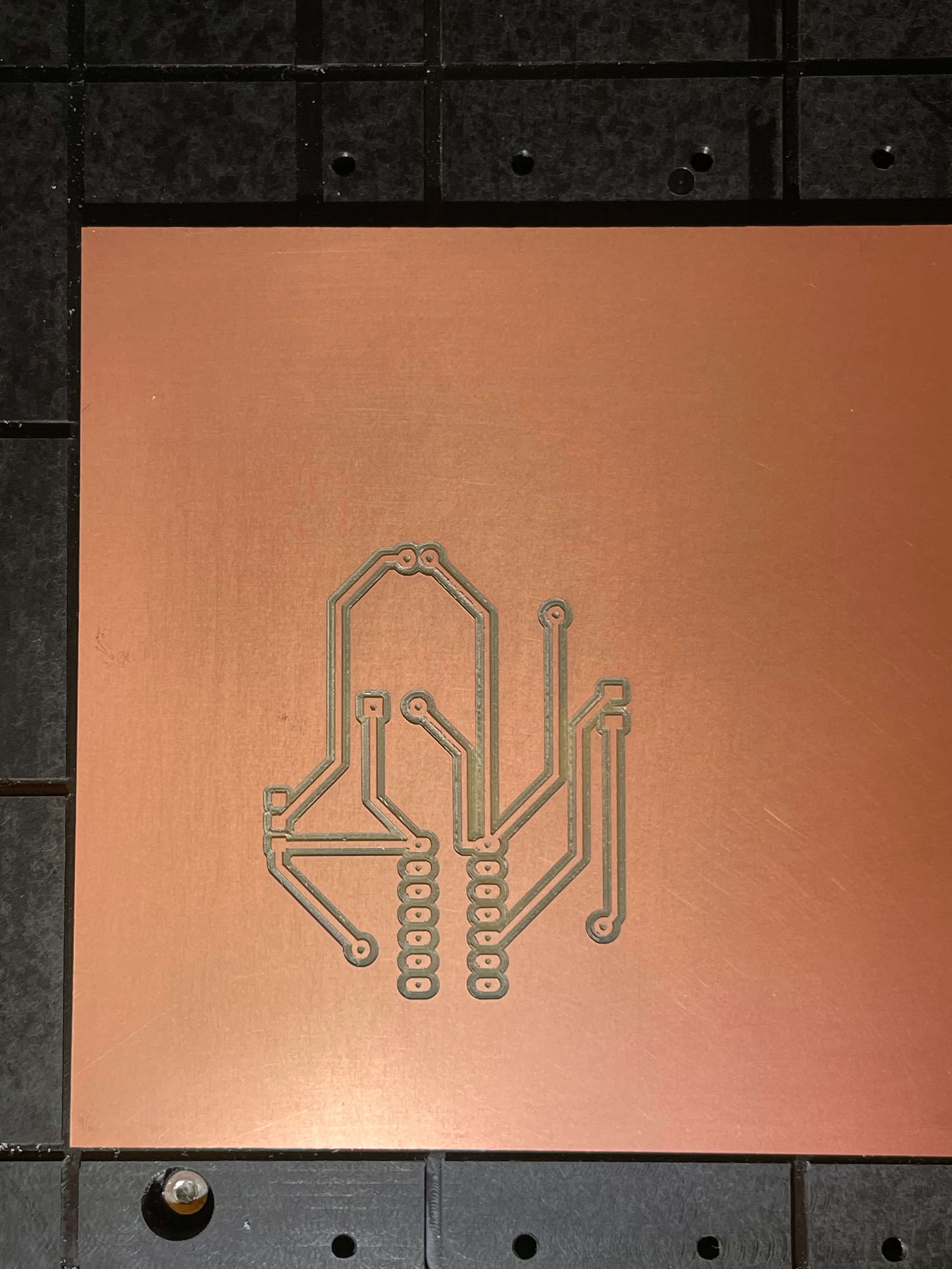
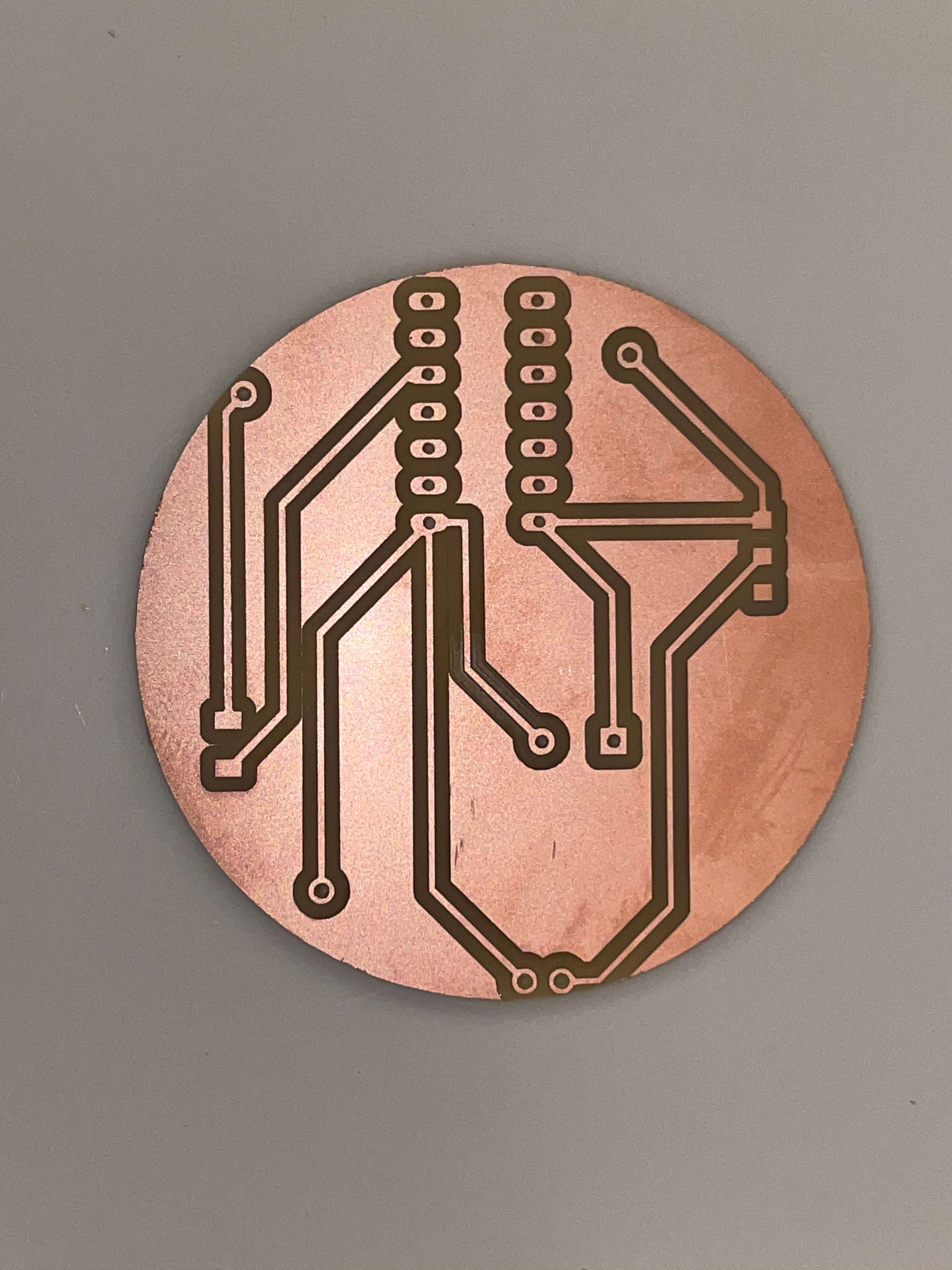
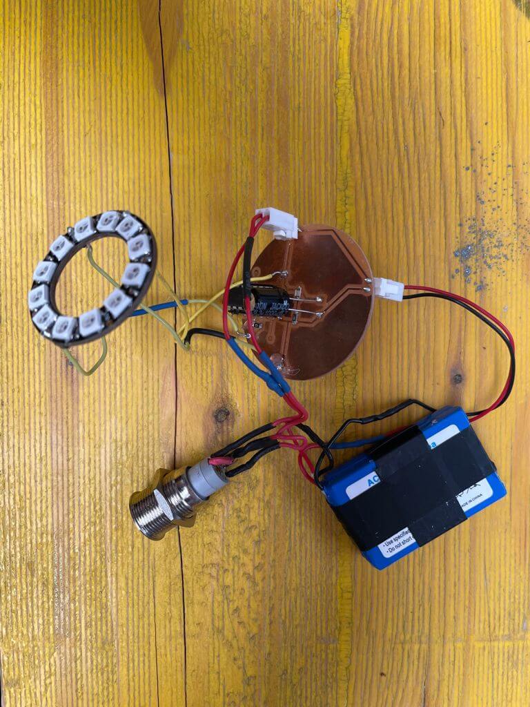
Having milled my board, I start drilling the holes where I need them (where I will solder the cables) and then I go on to solder the electronic components I need:
- RES
- CONDENSER
- ATTINY_44 SUPPORT
- EXTERNAL PINS
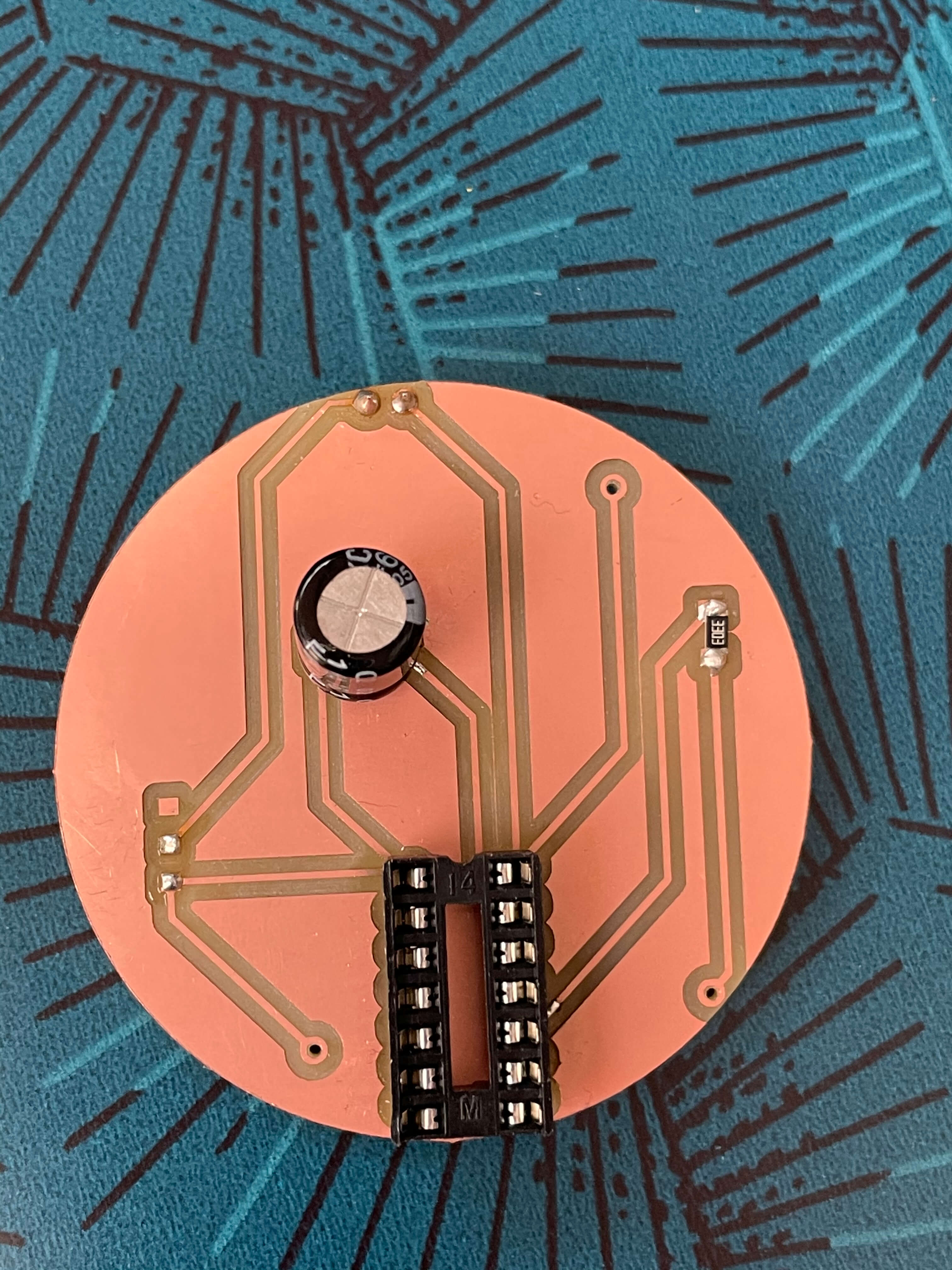
Once the Attiny_44 is programmed, I solder my cables to the board and connect the battery (I put two in series) and a button that will be used to switch the LedRing ON and OFF to the 2 external pins.
HOW COME I PUT THE BATTERIES IN SERIES?
I put the batteries in series because each of them "gave off" 3.3v but I needed at least 5v, so one battery was too little, so I put them in series being careful not to exceed the maximum value of volts supported.
HOW DO YOU PUT BATTERIES IN SERIES?
I connected the red cable of one battery with the black cable of the other battery, so I was left with a black cable from one battery and a red cable from the other battery. I then crimped these two exposed cables and attached a female connector to them, which I then attached to the male connector soldered to my board.
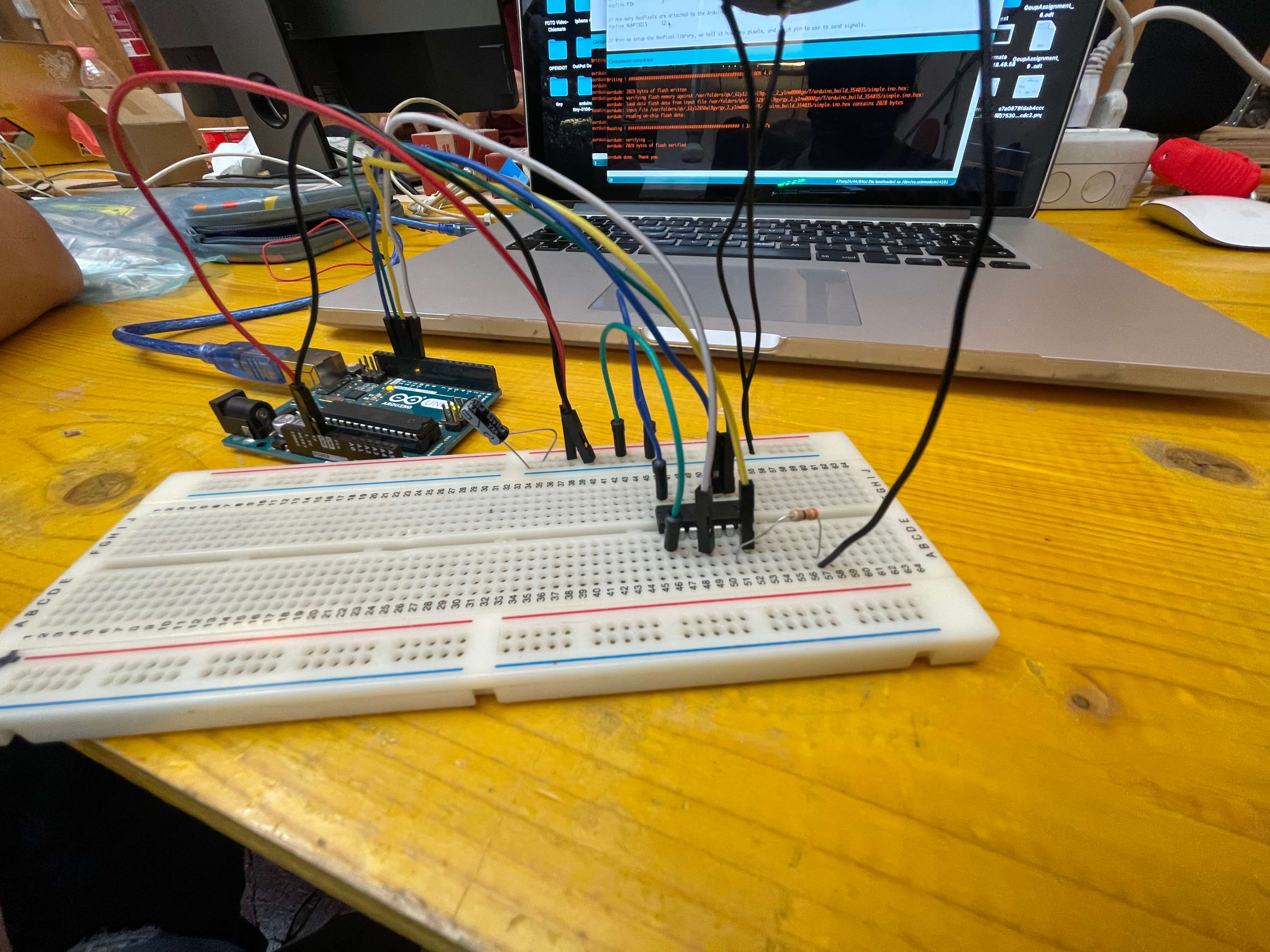
HOW I PROGRAMMED THE ATTINY_44
- BOARD: ATtiny24/44/84(a) (No Bootloader);
- CHIP: ATtiny44(a);
- CLOCK: 8 Mhz (internal);
- B.O.D. LEVEL: B.O.D. Disabled (saves power);
- SAVE EEPROM: EEPROM retained;
- PIN MAPPING: Clockwise;
- LTO: Enabled;
- TINY NEOPIXEL PORT: Port A;
- MILLS: Enabled;
- PORT: USB of the Arduino (unique number);
- PROGRAMMER: USBtinyISP;
To upload the code to the Arduino I need the Adafruit library which is the library from the parent company dedicated to my LedRing.
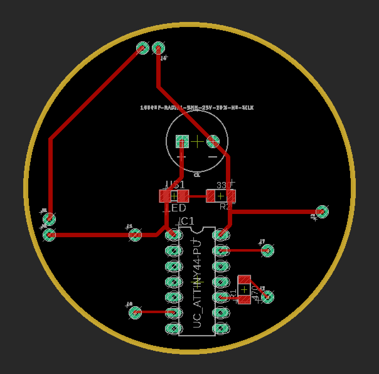
- SCHEMATIC
- BOARD
Group assignment
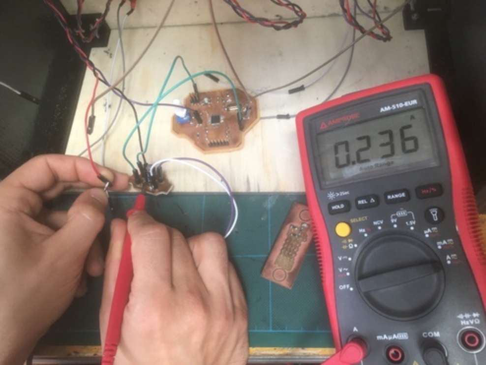
- This week we were to calculate\measure the power consumption of one of our outputs.
- We decided to measure the power spent by my LED matrixes.
- At their maximum brightness, Neopixels should draw up to 60 milliamps, but generally they are never turned up that way.
- Adafruit gives the following function to estimated the absolute maximum of minimum amps needed (at 60mA) and a generally acceptable value (at 20mA).
- number of NeoPixels * 20 mA ÷ 1,000 = x Amps minimum number of NeoPixels * 60 mA ÷ 1,000 = x Amps minimum
- Therefore, in my case these values would be:
- 256 * 20 mA ÷ 1,000 = 5.12 Amps minimum 256 * 60 mA ÷ 1,000 = 15.36 Amps minimum
- By datasheet each 8x8 Neomatrix has a maximum power consumption of (W): 0.24W x 64 = 15.36W, so that would be for all four (W): 0.24W x 256 = 61.44W.
- The formula to calculate power consumption is W(atts) = V(olts) × A(mpere); it can also be displayed as power consumption per hour, being Wh = W(atts) x h(our).
- Now, these were all estimates: it is time for me to check physically, using a voltimetre and a bench power supply.
Files