Computer-controlled Cutting
ASSIGNMENT
Individual Assignemnt
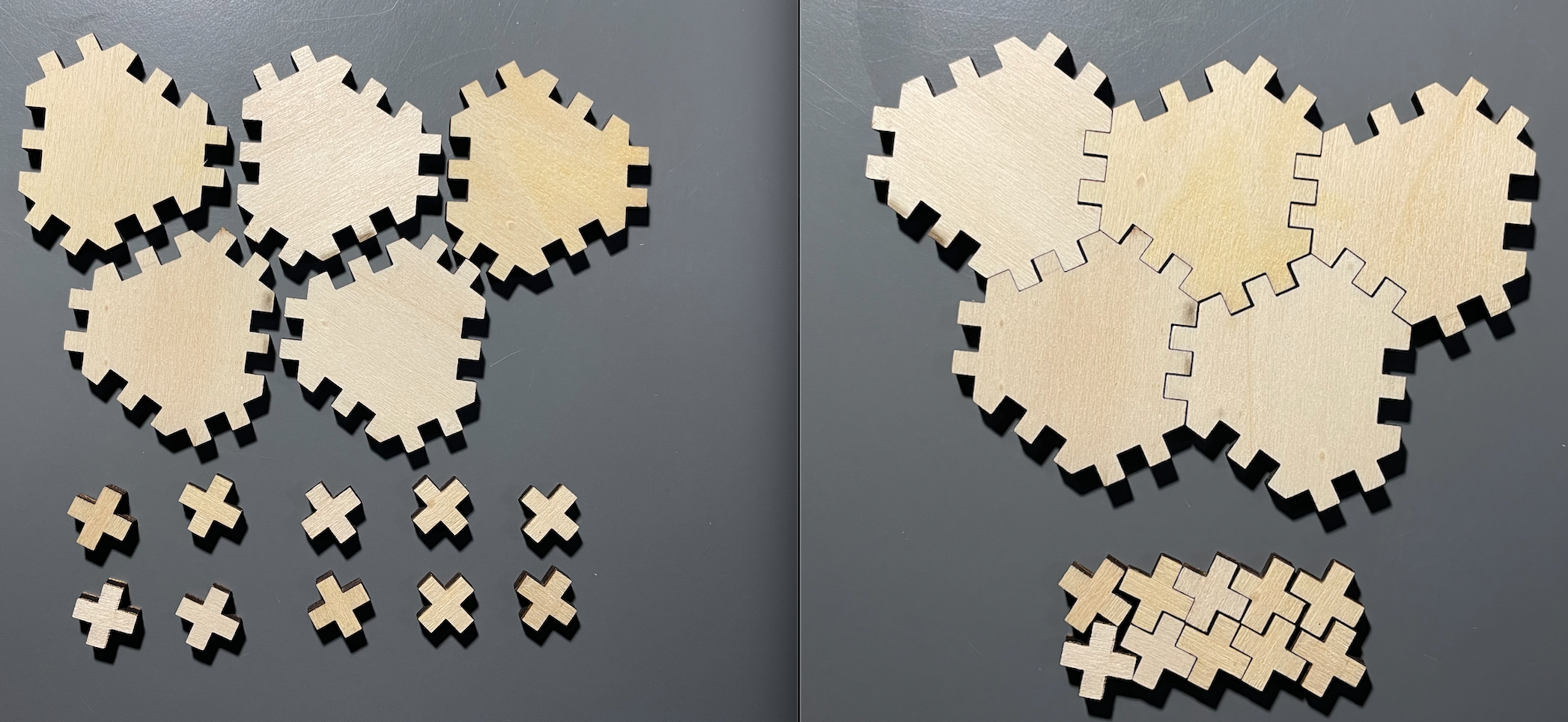
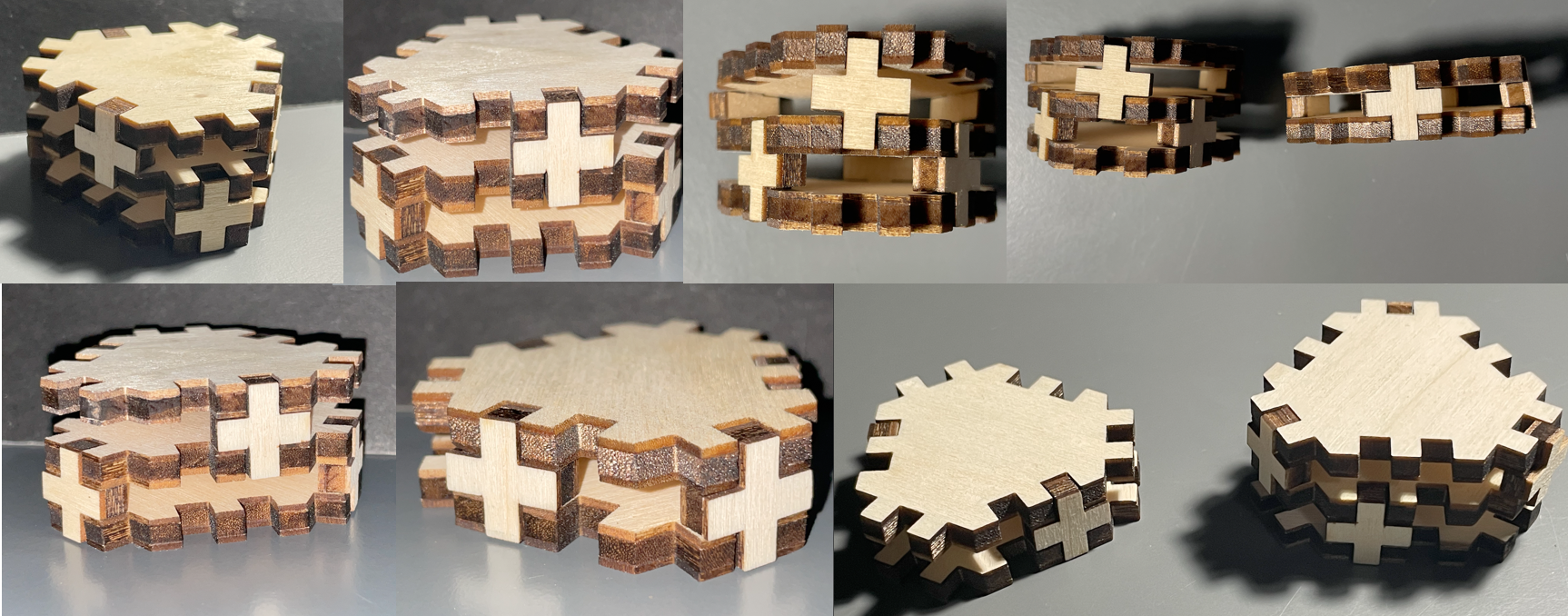
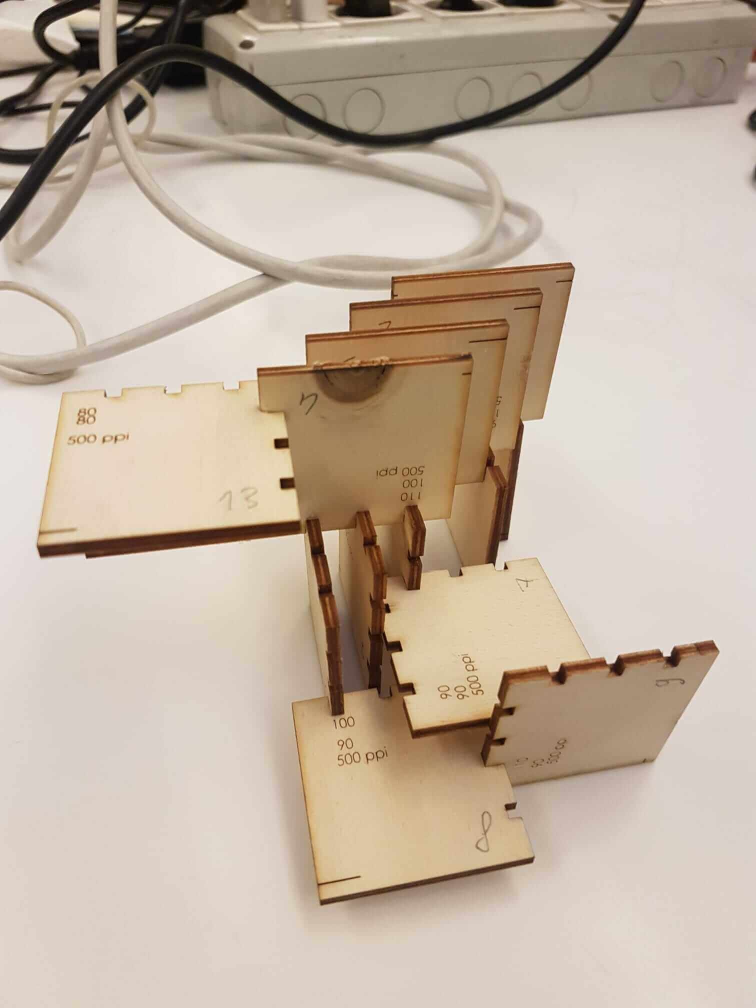
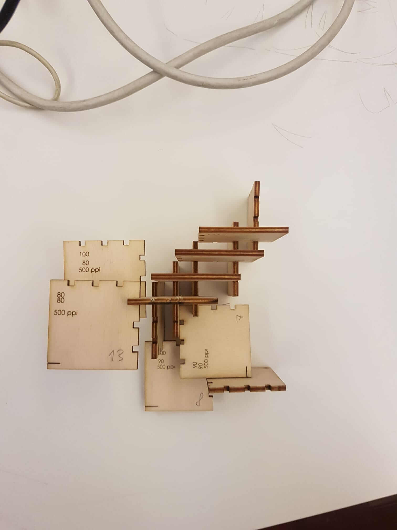
design, lasercut, and document a parametric press-fit construction kit, accounting for the lasercutter kerf, which can be assembled in multiple ways
Group assignment
characterize your lasercutter, making test part(s) that vary cutting settings and dimensions
WHAT IS VINIL CUTTER?
The Vinylcuter is a machine for tracing or cutting very thin materials such as paper, cardboard, vinyl and plastic materials using a blade that cuts very quickly. The machine receives the file, readable only in vector format (dxf / swg), or in pdf format; to produce this type of file you can use programs such as Inskape, Photoshop, Illustrator, Autocad. After designing the file, it must be loaded on the machine software where you can then modify some parameters that are distinguished by colors, for example the cutting density: on the red track I will have a heavier density, while on the lighter blue track. The blade can be adjusted and the adjustment depends only on the type of material you want to work on.
Individual Assignement
WORK FLOW
Vynil cutter - Setting up and exporting a sketch
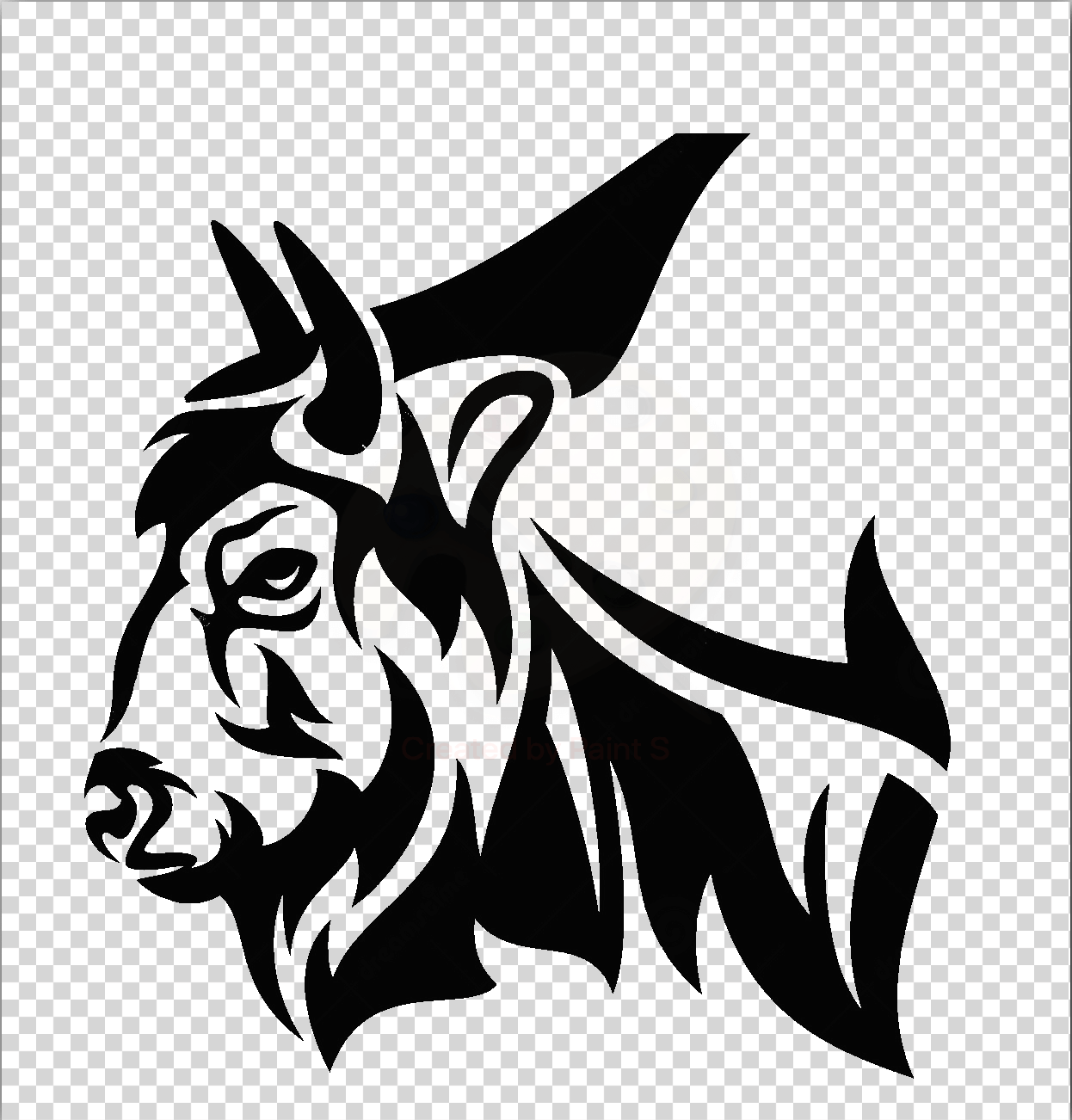
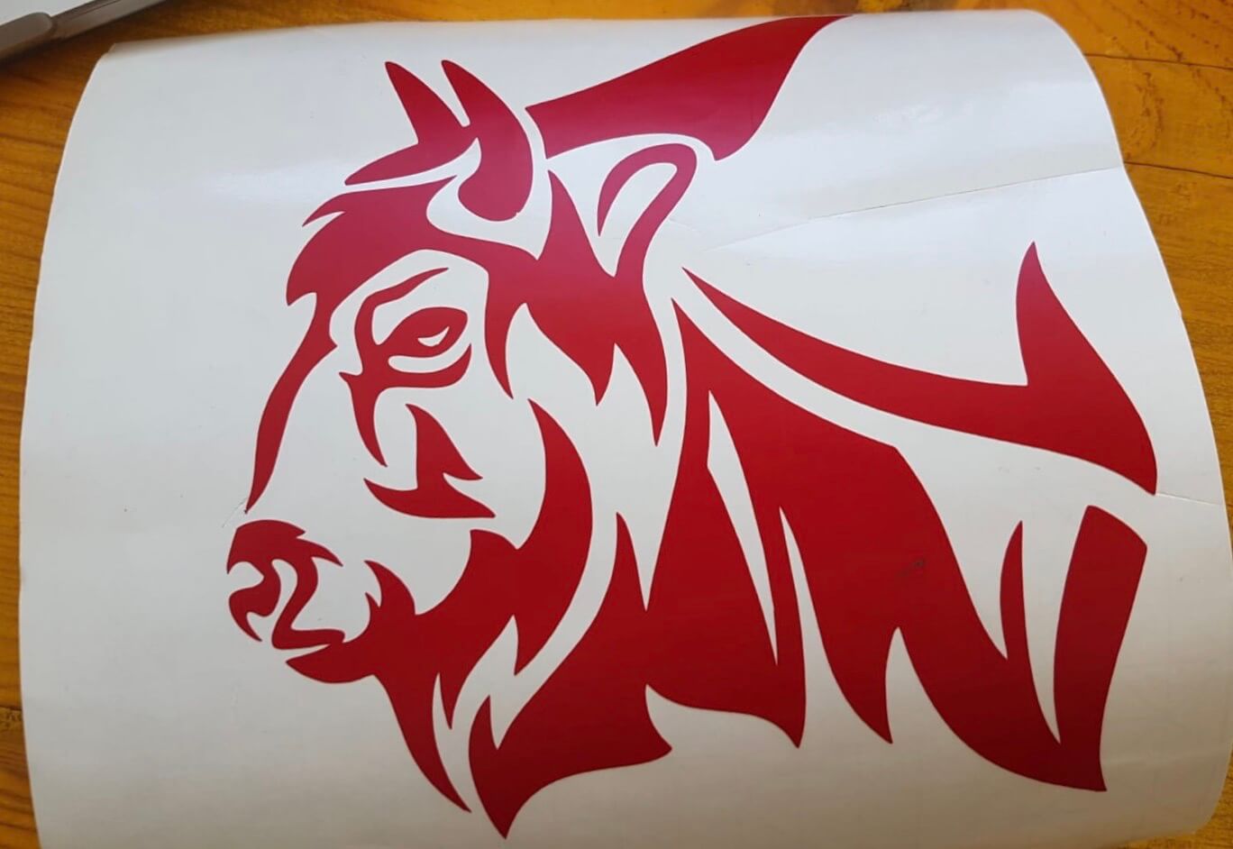
To extract a fantasy sticker from the cutting plotter, I had to prepare a picture file that would be sent to the car together with the duct tape. This process consists of several passages, depending on the need for the final result, but generally it is good to start with an editor Svg - Dxf as AutoCad [dxf], Illustrator [swg] or Inskape to work on the desired file. For starters, I used a Svg file from my gallery and I consider my logo to be the gauge of a bison.
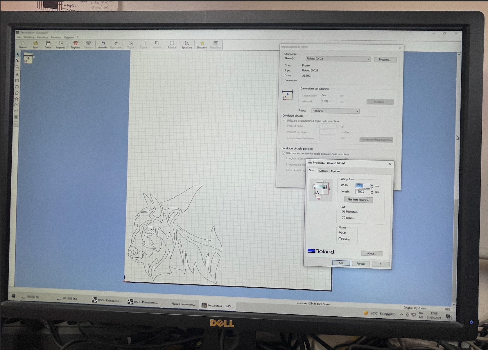
I downsized and aligned the image to the page, so I exported the Png file to the file - > Export PNG Image...menus command. The card that opens with these instructions requires a few technical details to be filled, such as the size of the export area and the desired dice. In my case, I only made exports of the bison shaft.
Vynil cutter - cutstudy and plotter installation
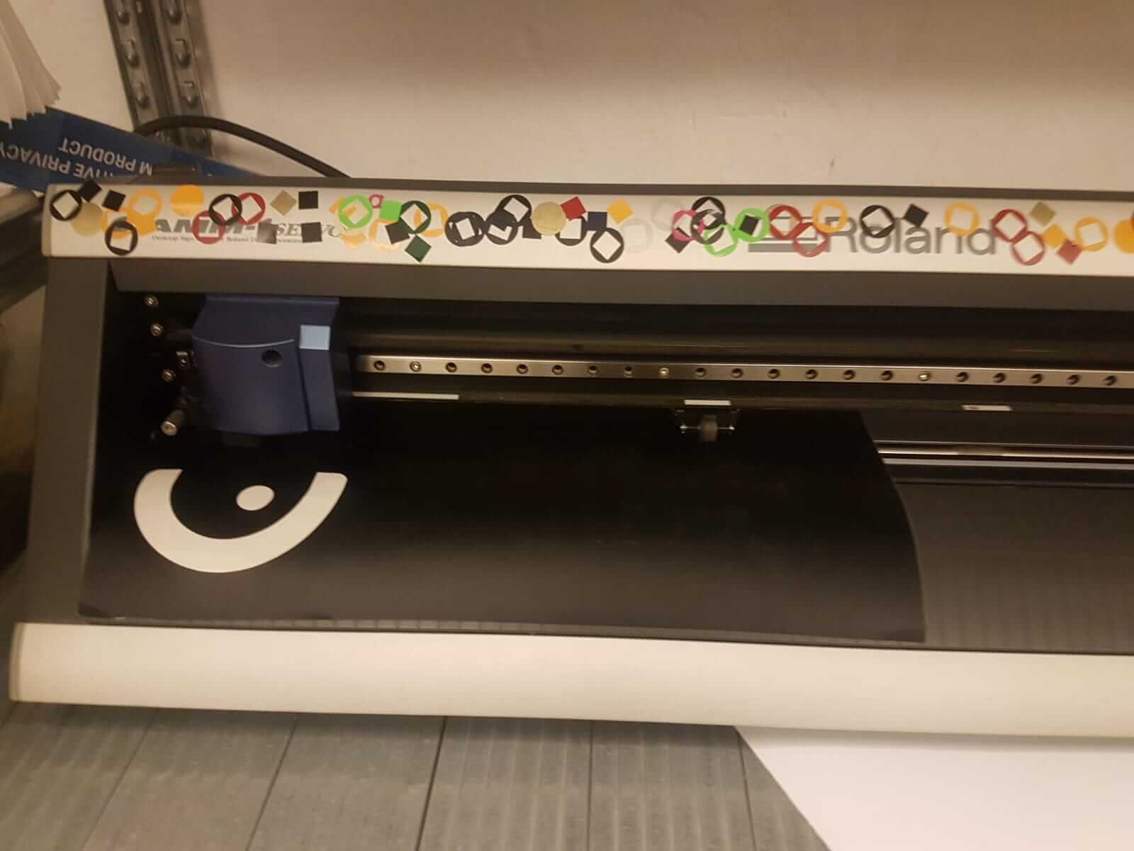
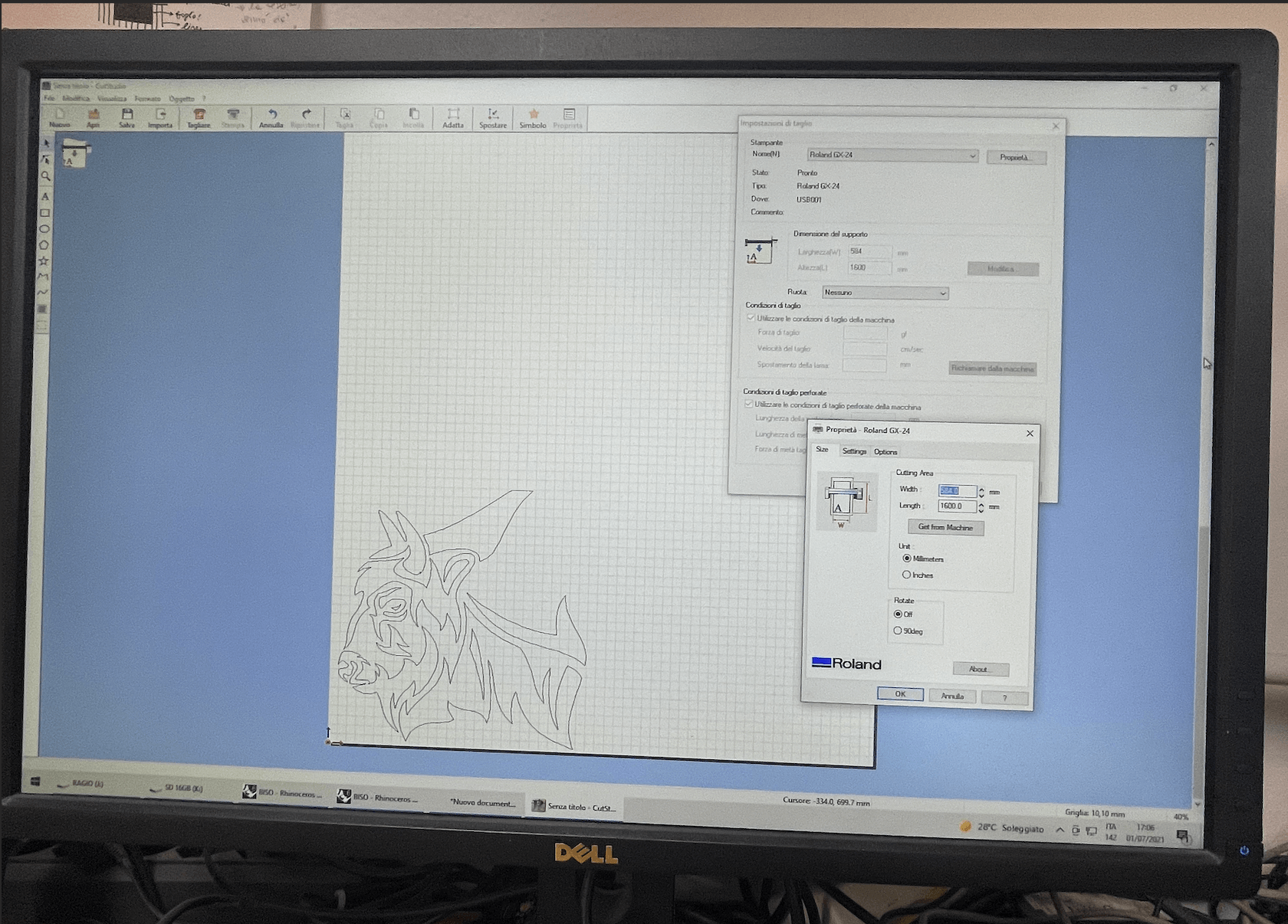
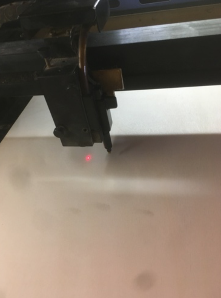
With this new Png image I carried out the upload in software CutStudio, which is the proprietary application to perform the plotter Roland. Once the position and the size of the images, it is important to use the Image outline command visualized by clicking the right - hand buttons of the mouse on the figures you wish to cut. This is necessary to define the path of cut - off for the plotter, otherwise the machine will do nothing. I turned the cutting plotter ON and I put my vinyl tape on, of a suitable dimension to contain my image of the bison.
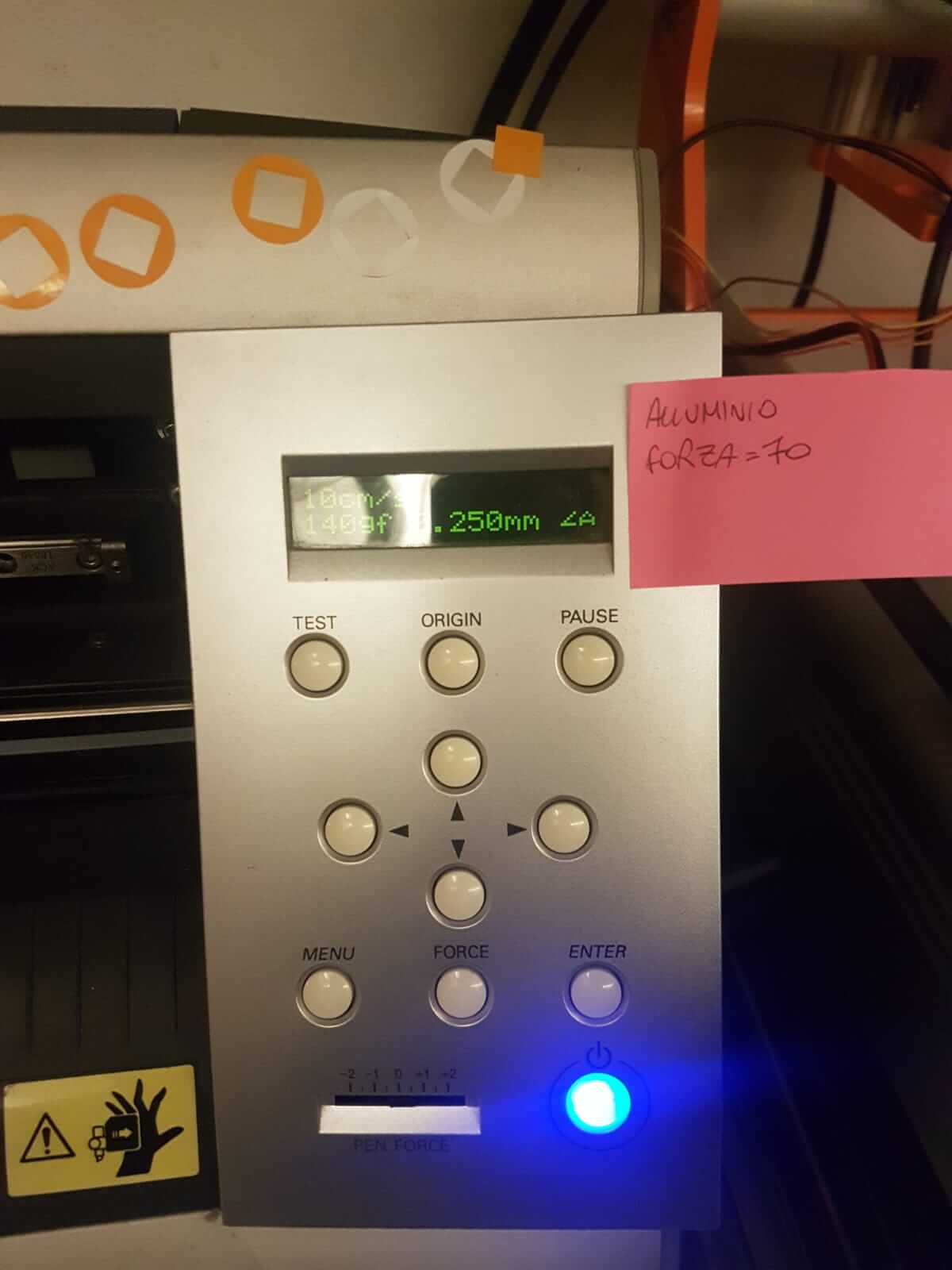
Once the machine was set, I made a cuttlebutt through the cutlet that opens a window of approaches: where many variables can be changed such as the blade's strength and the speed of the head. After correctly setting the necessary parameters, I only pressed the get-machine that not only confirms the values set in the box box, but also recognises the tape size inserted within it through a sensor photo to define the precise part of the area to be cut.
Vyinl - removal of the residue and transfer of the film
After a few minutes, the machine finished inciding and I, with the sticker in my hands, started to take the area out of the area not concerned by my sticker. It's a process that requires a lot of concentration and precision: in fact, I used pliers, scalpel and a small snipe knife with a forking so that I wouldn t risk ruining my design. After the removal of the intact parts, I applied a transparent film on vinyl tape carefully. This film is used as a transfer to extract the sticker from its base paper and apply it where it is preferred.
LASER CUT
I started with an isosceles triangle and then smoothed it out and made the joints.
The laser machine we have in the workshop is a powerful machine that cuts wood and polymers.
Its resolution is up to 1500 dpi, it has a powerful laser of up to 100W, an autofocus system, and the table dimensions are 860 x 610 mm.
The steps to operate the machine are very simple:
- you have to place the material to be lasered on the table;
- If the material is curved or not completely flat, weights can be placed to hold it down, thus reducing deformation;
- once the material has been positioned, the "Z" axis can be focused.
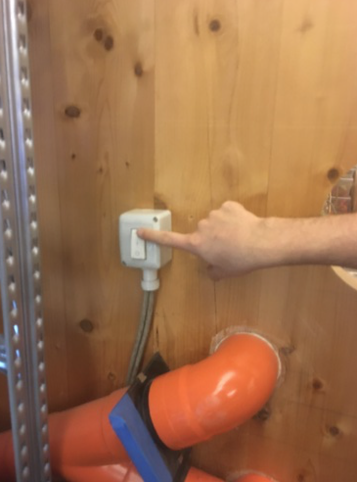
-Switch on the vacuum cleaner which is located on the left-hand side of the machine. The suction of gases and fumes is very important because they could damage some human senses (sight, smell) even if only temporarily. Other materials, on the other hand, are harmful, but this must be researched on Google before selecting an unknown material.
- to set the "X-Y" axis, on the other hand, either set it to "HOME" or to "RELATIVE", what is the difference?
On HOME the laser will start from XY=0, while on RELATIVE the laser will start from XY = where we place it. This means that if the wood we are using has already undergone some thalings, instead of using a new one we can reuse that one and thus have less waste of material.
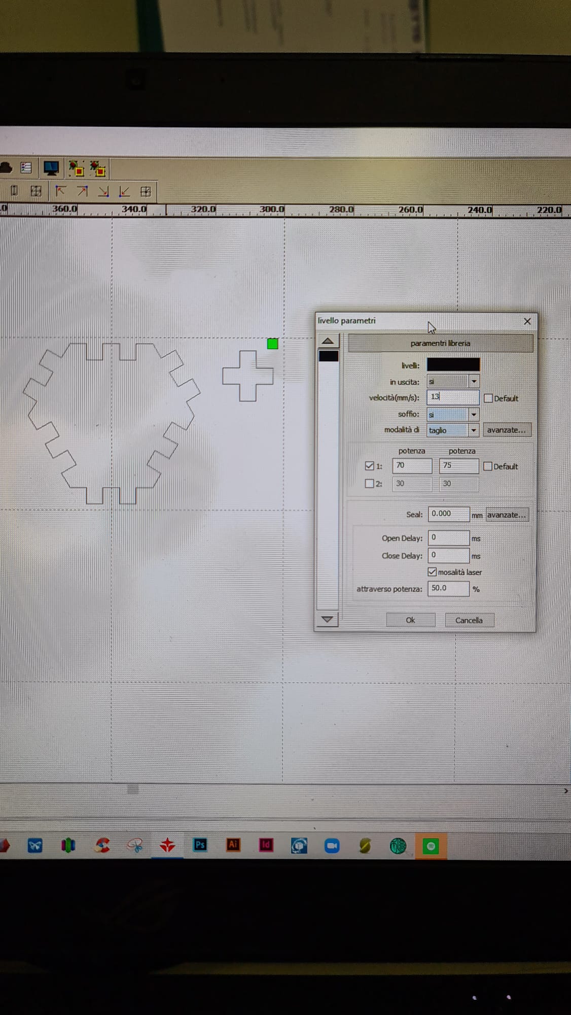
- once the axes "X-Y-Z" are set, we can proceed to the cutting settings, so, according to the "stock" we are using, we will have to increase or decrease the cutting POWER and SPEED.
In my case I used a 5mm panel and therefore, I have a power of 70-75 with a speed of 13 mm/s.
|
|
- LARGE stl
- SMALL stl
- LARGE dxf
- SMALL dxf
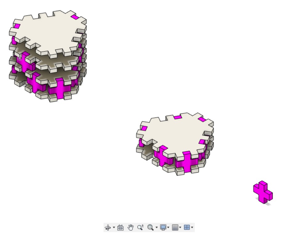
- VARIANT PUZZLE - COMBINATION v1.f3d
Group Assignement
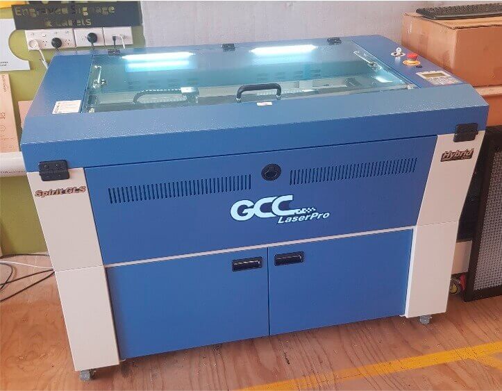
The OpenDot laser cutter is a CO2 GCC SpiritGLS. It has a working area of 960x610 mm and can comfortably cut acrylic and plywood up to about 12 mm thick.
|
|
WORKFLOW FOR CUTTING
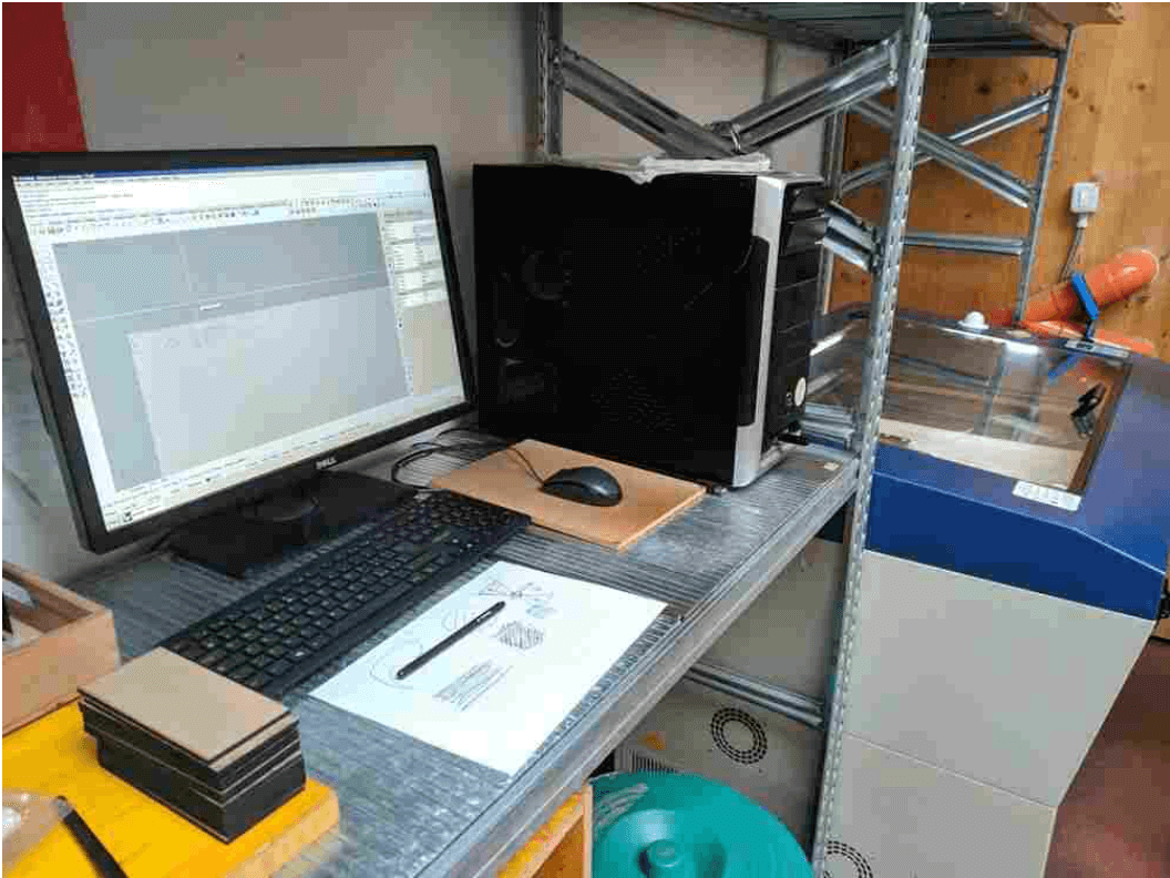
The PC works with Rhino 7 software on the Windows platform, configured to open a template file with the laser cutter workspace on a locked level.
The workflow for cutting a file is:
- Use the Import command to import a DXF file from a USB key.
- Clean up the contents of the file:
- position the project in the work area;
- join segmented paths by selecting everything and using the Join command;
- make sure there are NO duplicate curved lines;
- move the curves to different levels depending on the process to be applied (cut vs engrave);
- make sure that all Print Color shapes are set to By Layer;
- If there are shapes to complete, use the Hatch command.
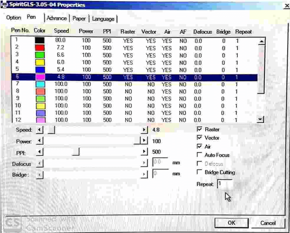
- Open and configure the Print window:
- open the properties window;
- set the preferences for each level by changing the 'pen' settings;
- generally the indications are to leave the Power workflow at 100% and to adjust the speed instead;
- for specific cases it may be necessary to adjust the Power and PPI settings;
- On the advanced page set the position to relative:
- this way the laser can be positioned manually before cutting and the laser cutter will be relative to this position. This simplifies the accurate positioning of the laser on already partially used material;
- in the main print window you can adjust the origin of the print area using the Window selector. This can be useful for aligning file contents with the laser;
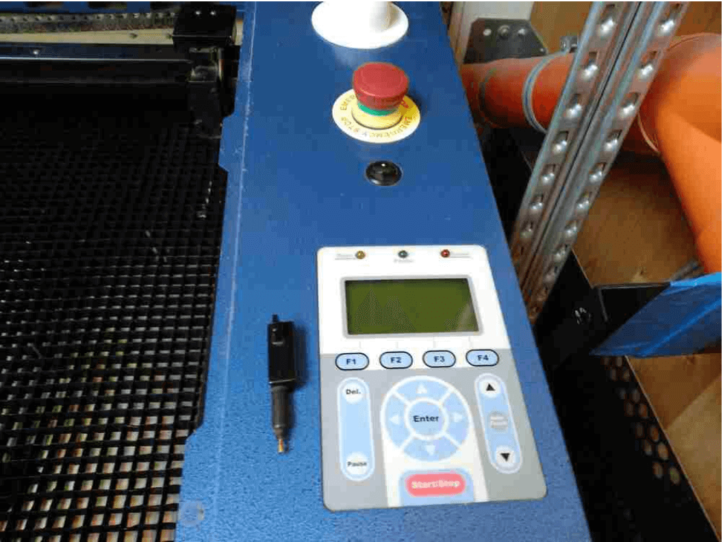
- Turn ON the laser cutter.
- wait for the initialization to finish (limit check);
- connect the level probe, move the laser to the material and press the automatic level key;
- After rechecking everything on Rhino, press print to send the document to the printer.
- After positioning the cutting head and turning on the air pump, you can close the hood and start cutting using the start/stop button on the machine.
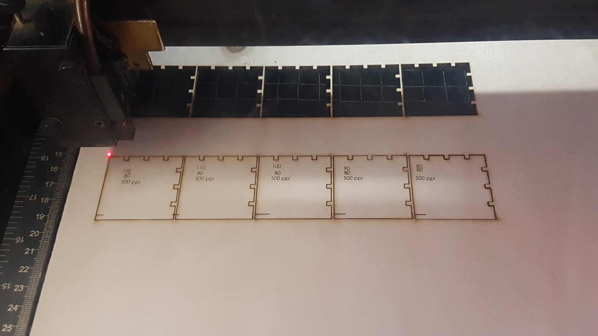
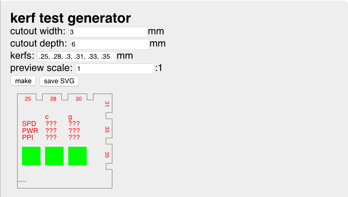
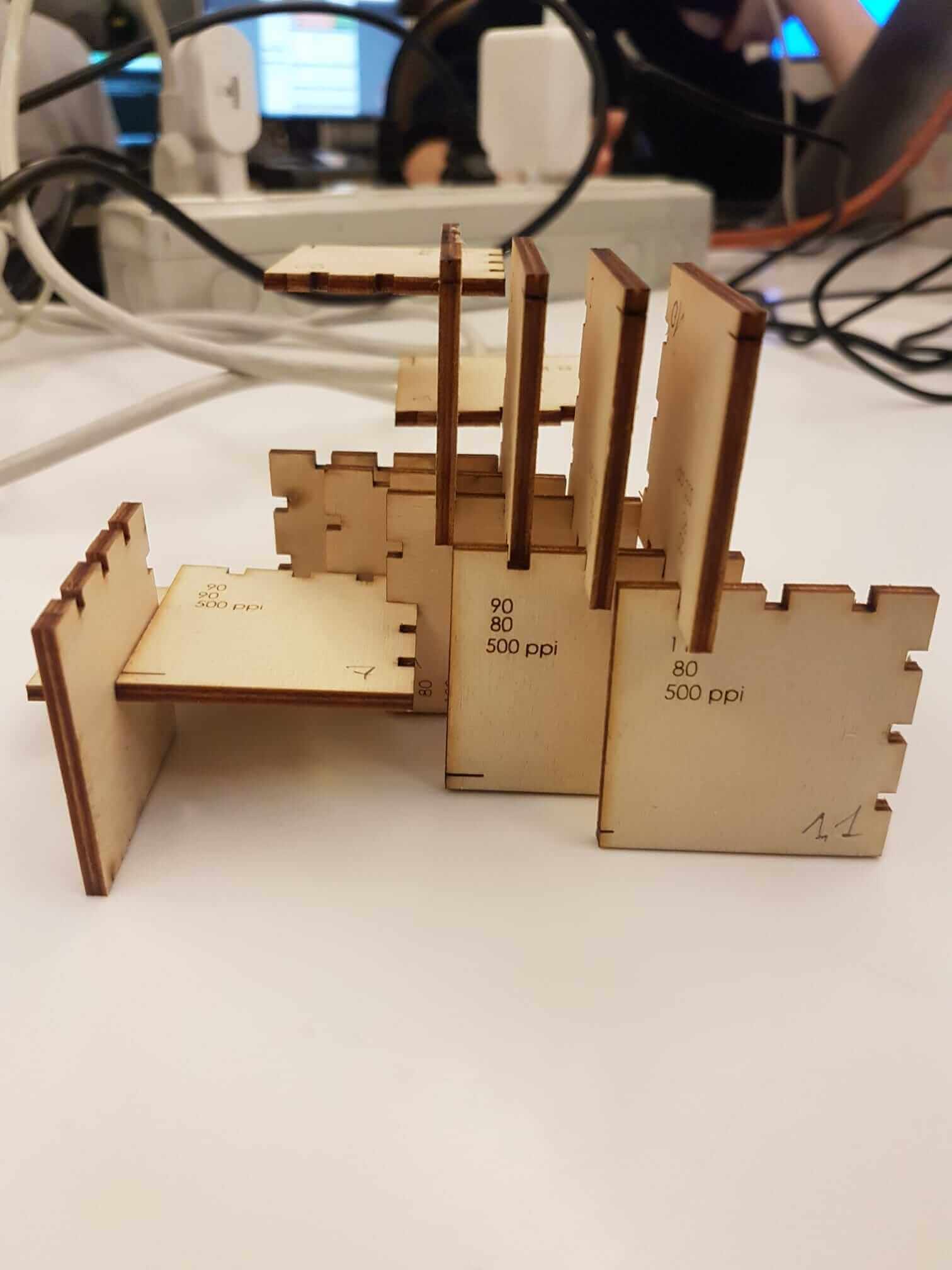
We measured with the gauge the plywood to be cut, and found a thickness of 2.9 mm. We then used the generator to generate a test pattern with corresponding cutouts and a cutting scale from 0.25 to 0.35 mm. We measured a cut of 0.3 mm and found that the insufficient adjustment slots for a kerf of 0.25 mm gave a good pressure seal on the joints. We then performed a series of tests on the speed and power settings. We used the laboratory's guidelines of 6% speed and 100% power at 500 PPI as a starting point and created a matrix of adjusted test cuts relative to this initial value. The columns have a relative speed setting of 80%, 90%, 100%, 110% and 120% (left to right) wrt, the guideline 6%, while the columns have a power setting of 100%, 90% and 80% (top to bottom). Approaching the low power, high speed angle of the matrix, the laser began to cut the entire material with difficulty, with the result that the final piece in the third column was not easily removable from the surrounding material.
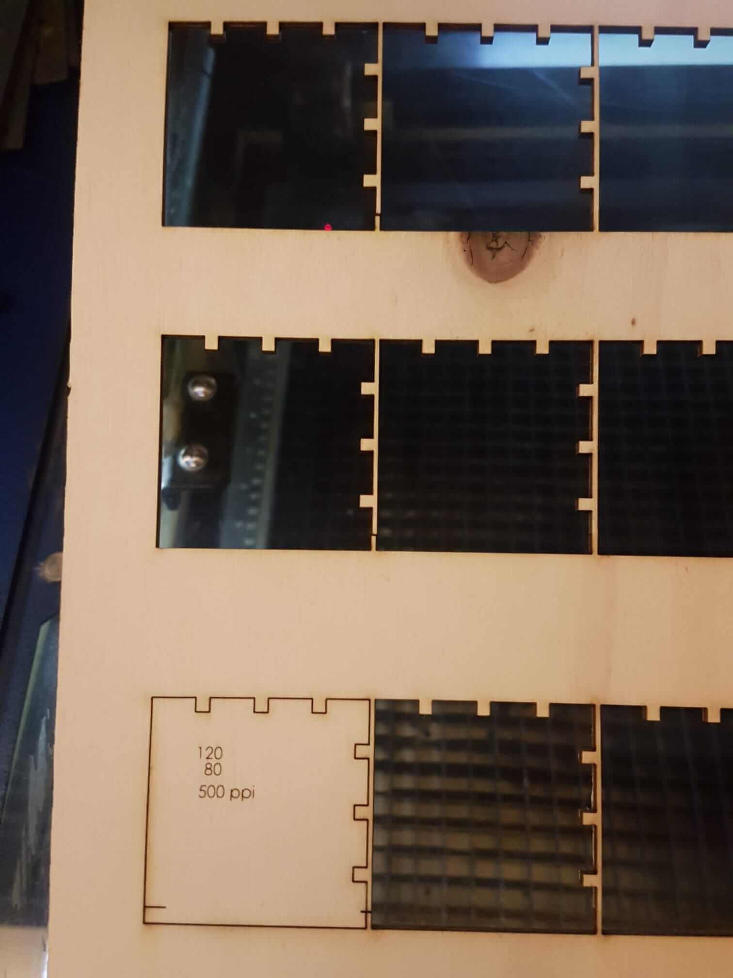
We cut the matrix row by row with the same setting as indicated in Rhino: at the beginning we placed the five cuts, one per column, on five layers and gave them five different colors. Then we labeled them on a separate layer for engraving and configured the different pen settings.
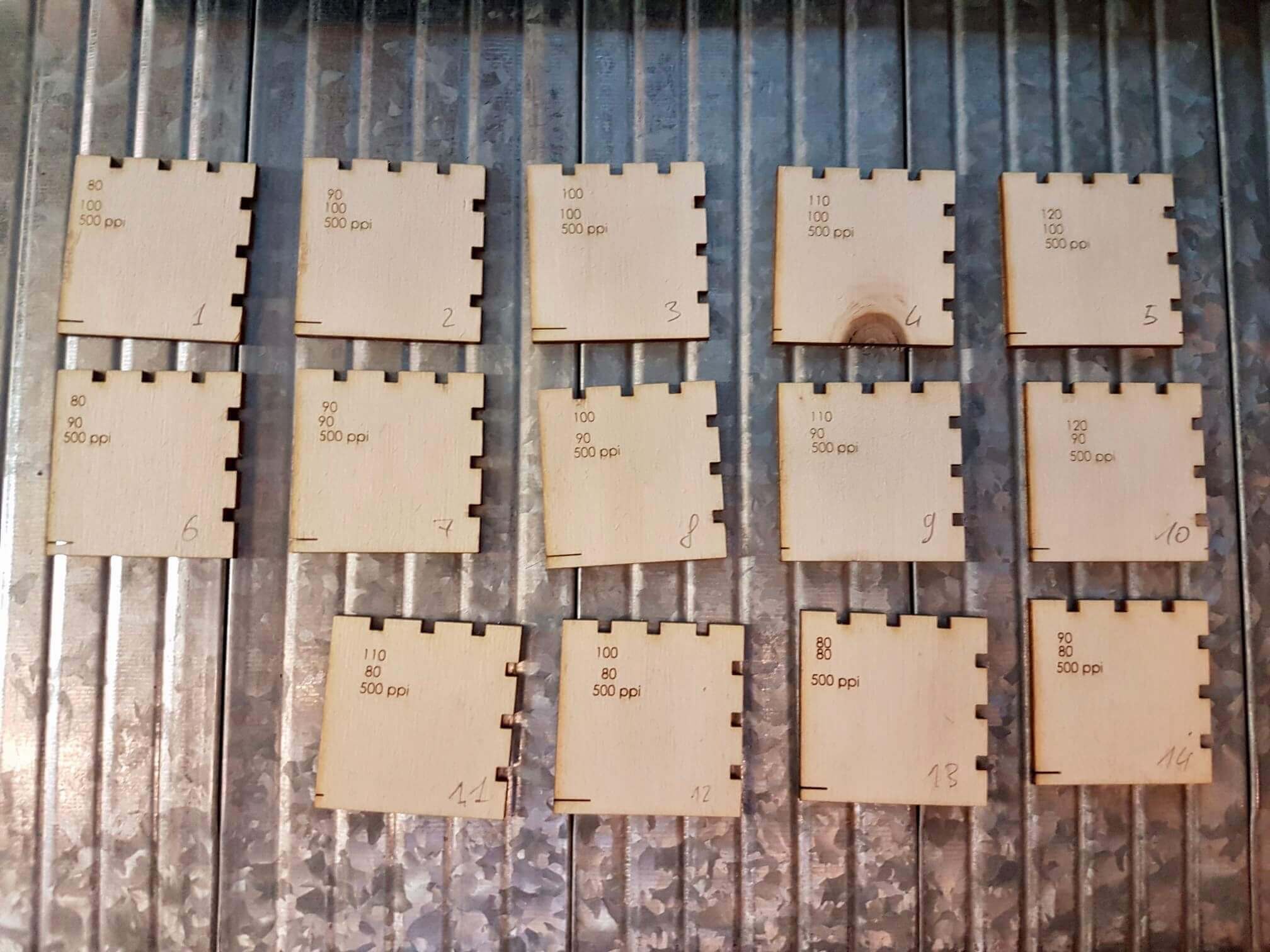
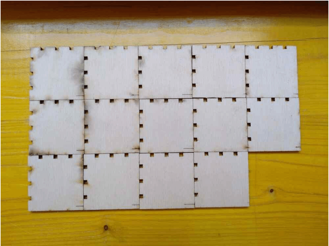
Based on these results we concluded that cutting at 6% speed and 80% power gave the best results compared to the settings we had tested, but we noticed that the 120% speed and 100% power gave similar results using the maximum laser output power, with time optimization.
|
|
|