3D Scanning and Printing
Individual Assignement
3D scan an object
WORK FLOW
Application
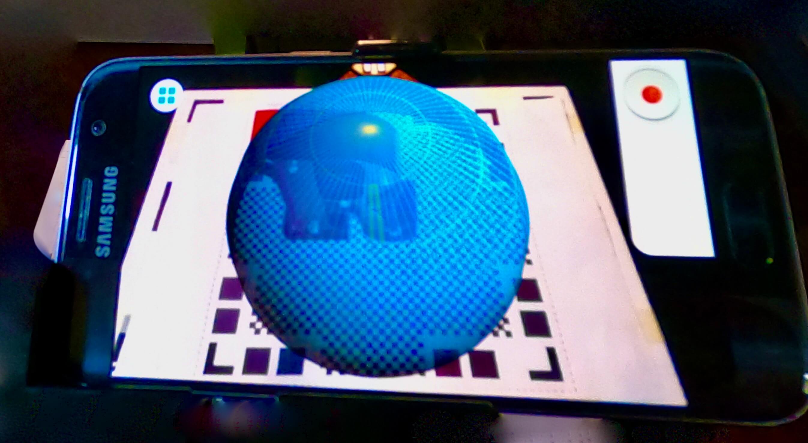
To scan a 3D object, I chose to use (Qlone): an application for both iOS and Android phones.
The application is very professional and intuitive to use, but to better understand every single function available I went to see two tutorials:
(What is Qlone?) and (How to use Qlone?).

Photos of my Object
Following these short, simple and clear tutorials I was able to make my 3D scan.
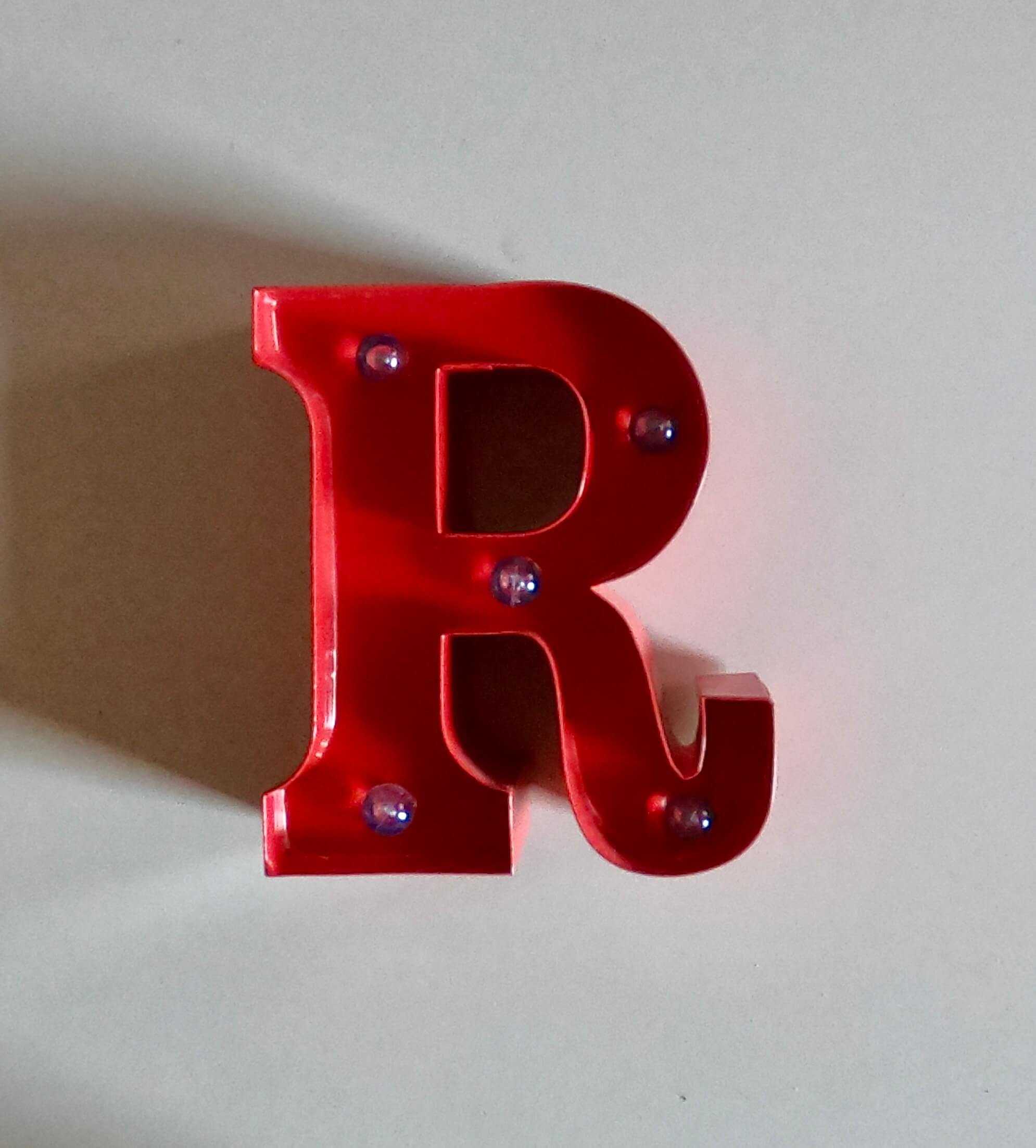
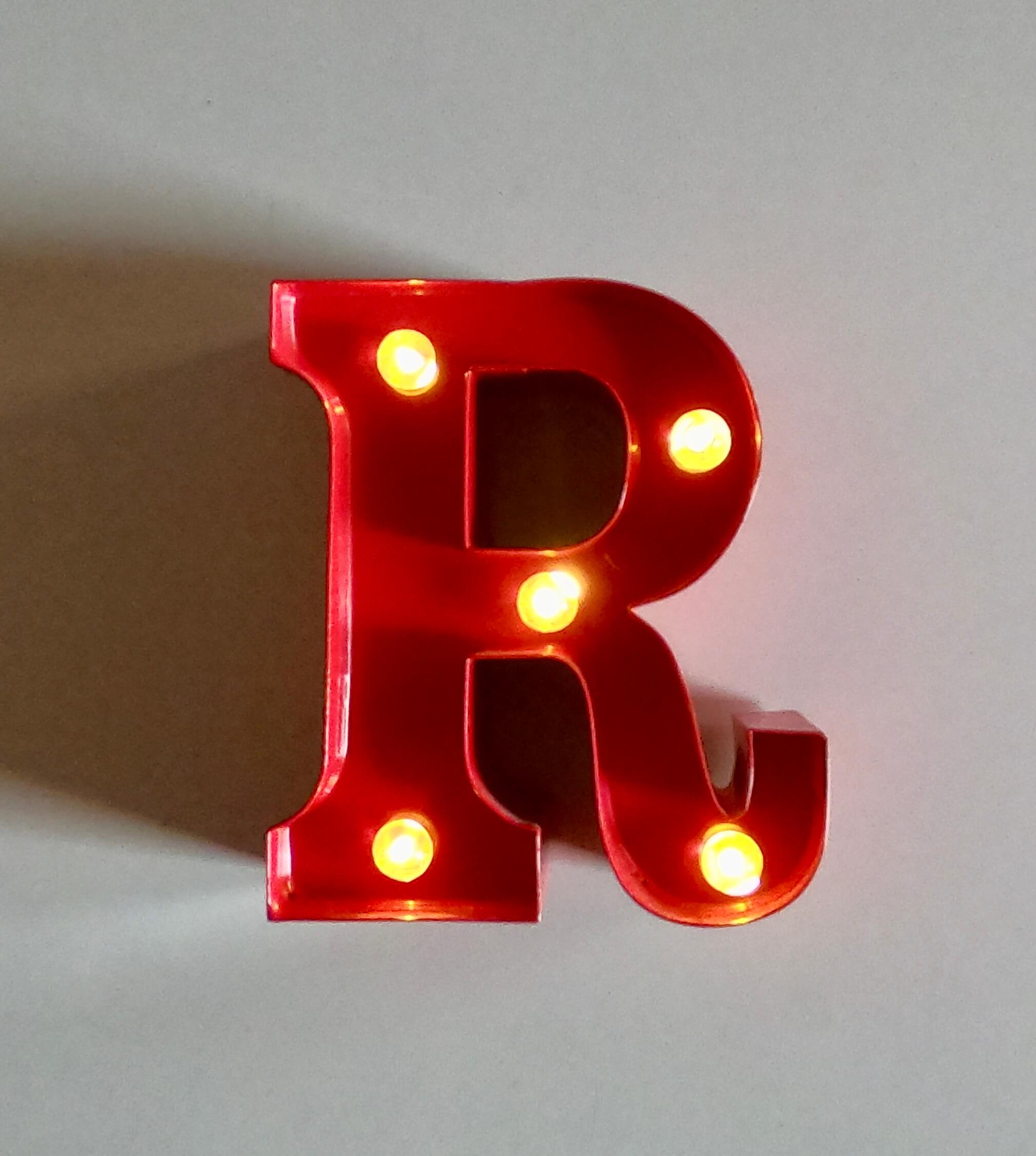
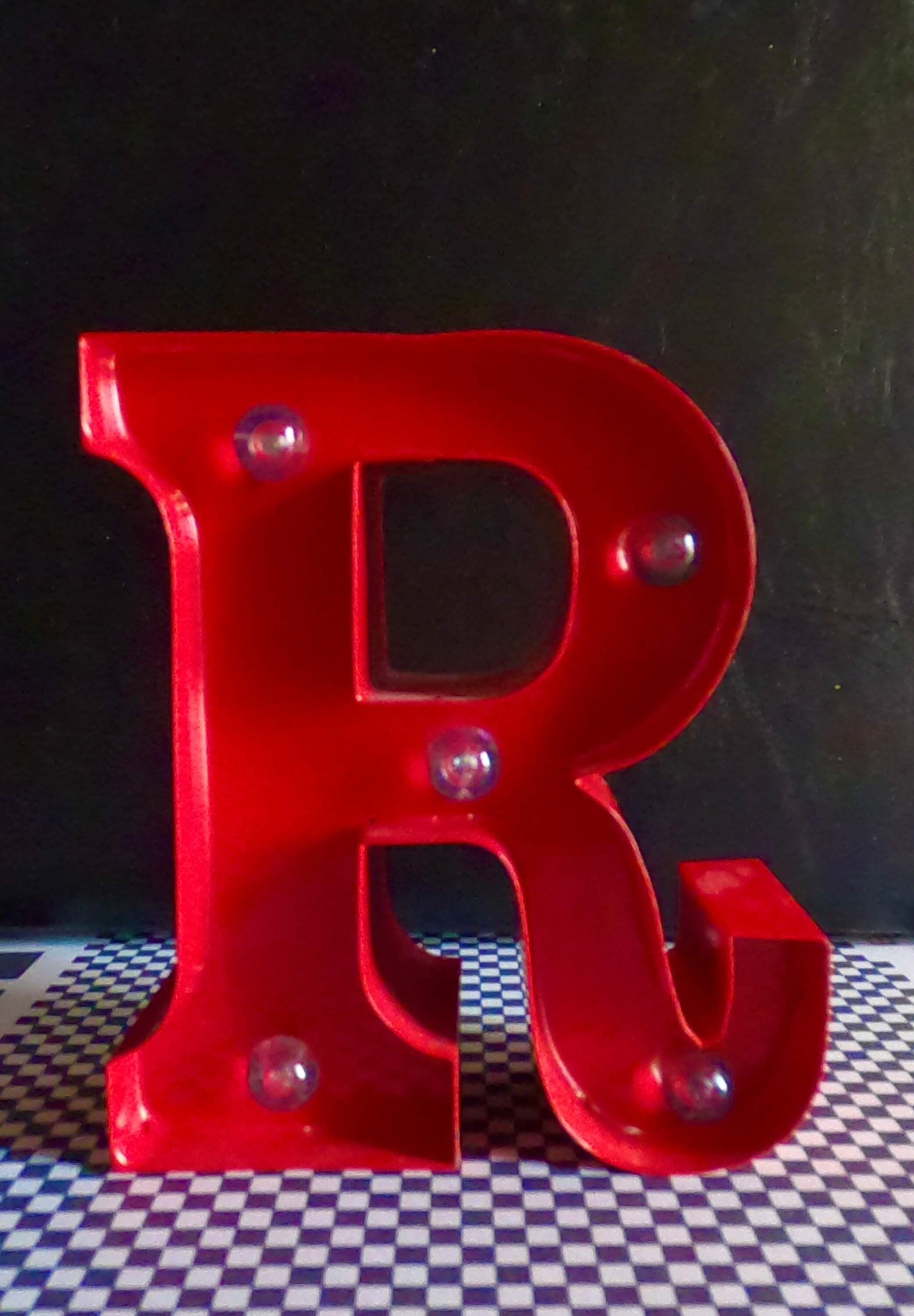
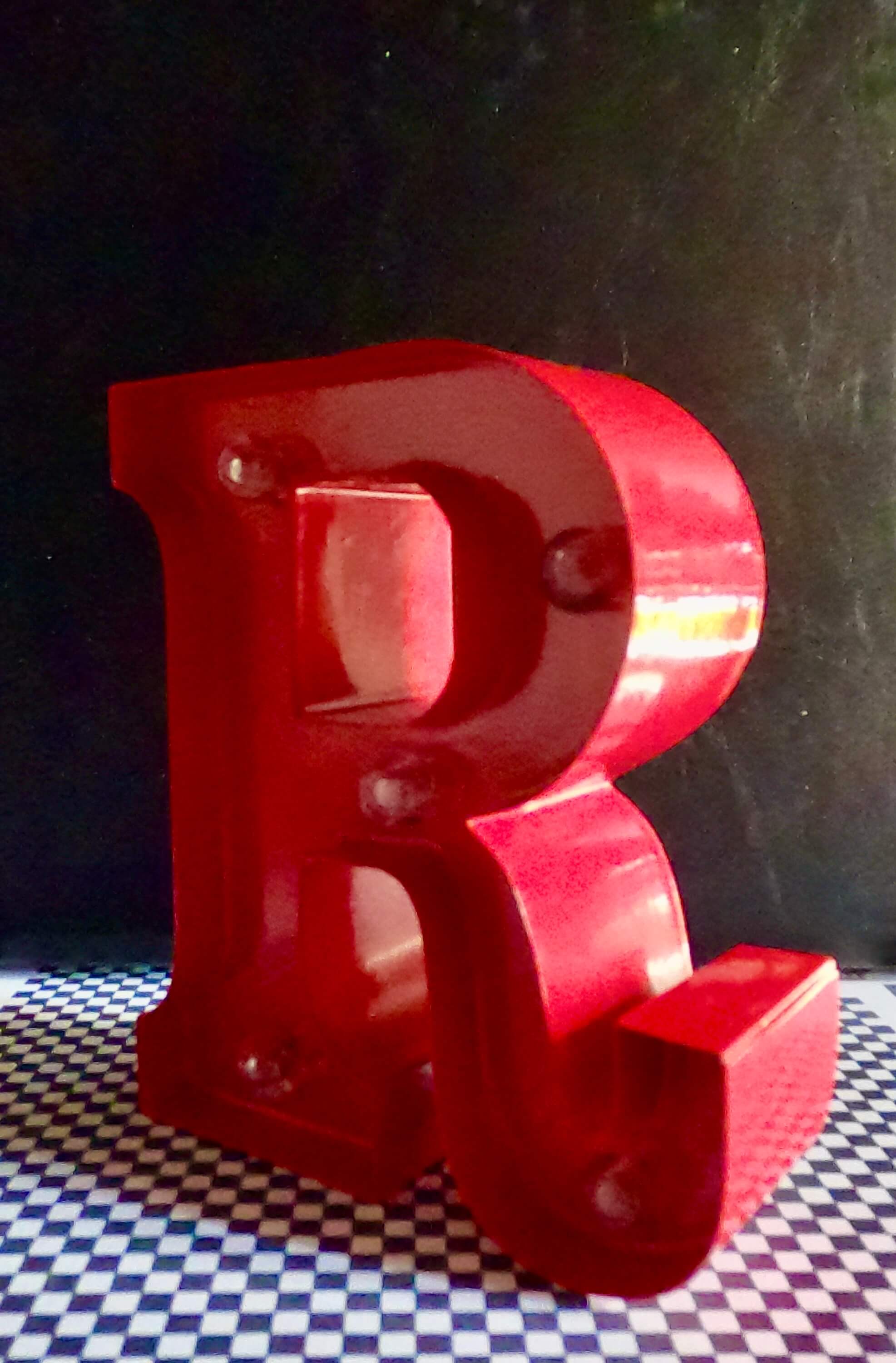
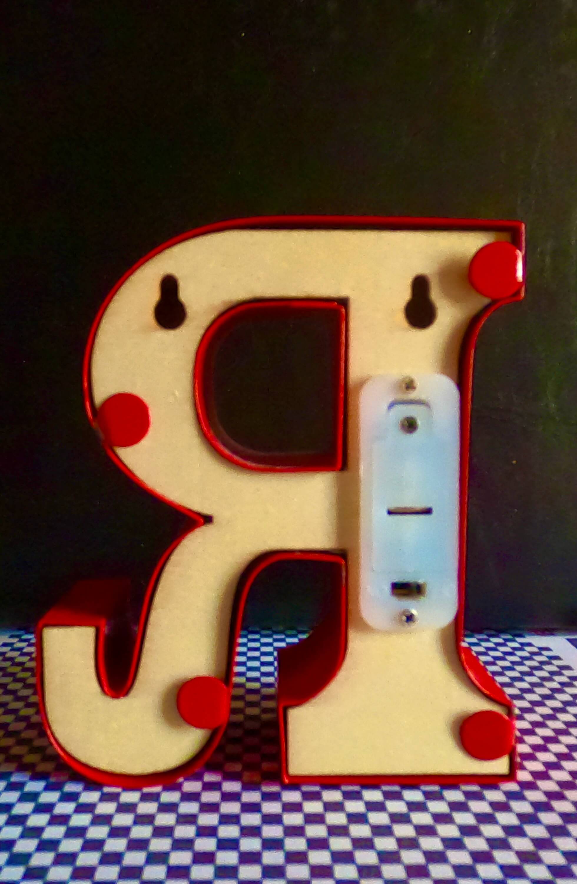
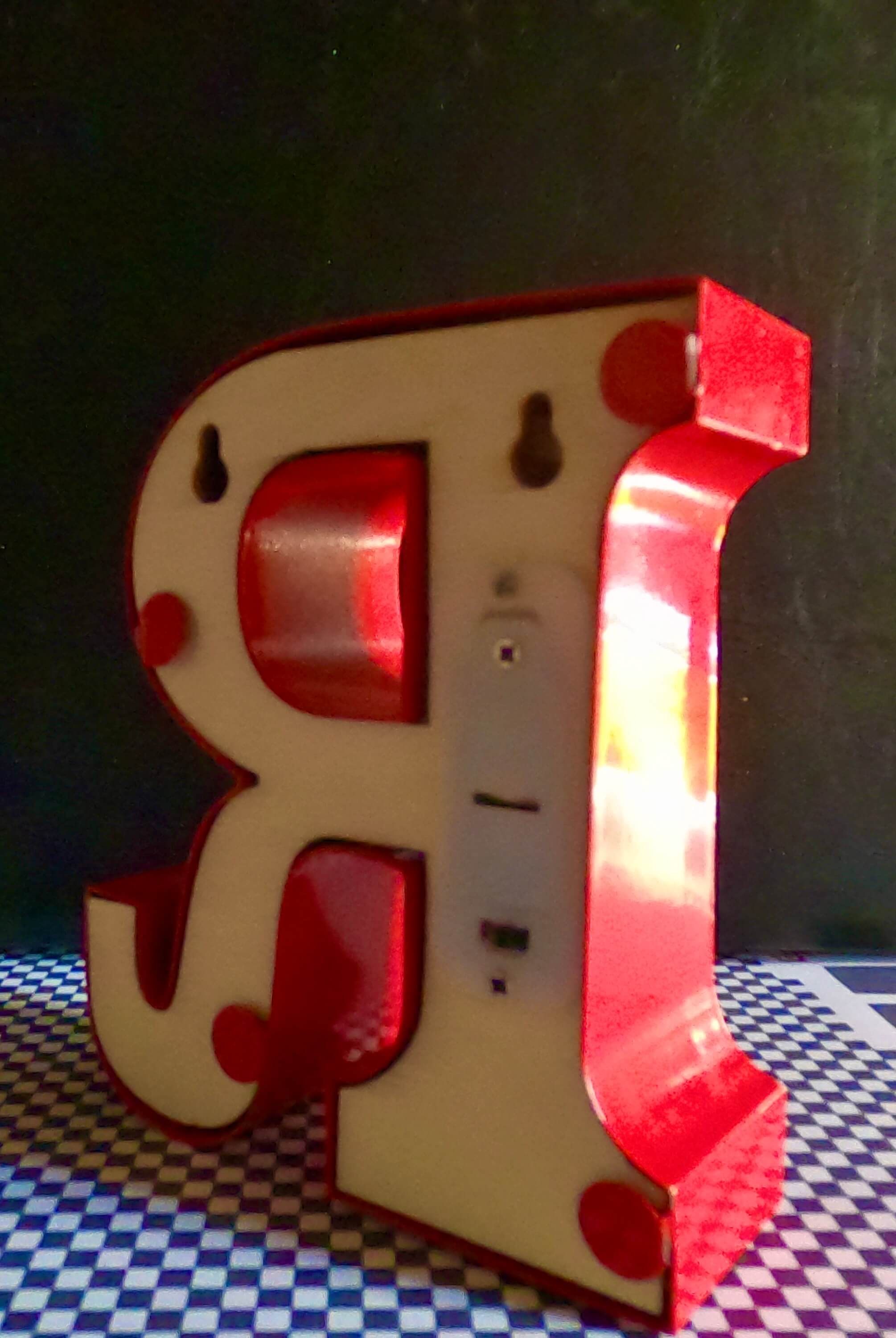
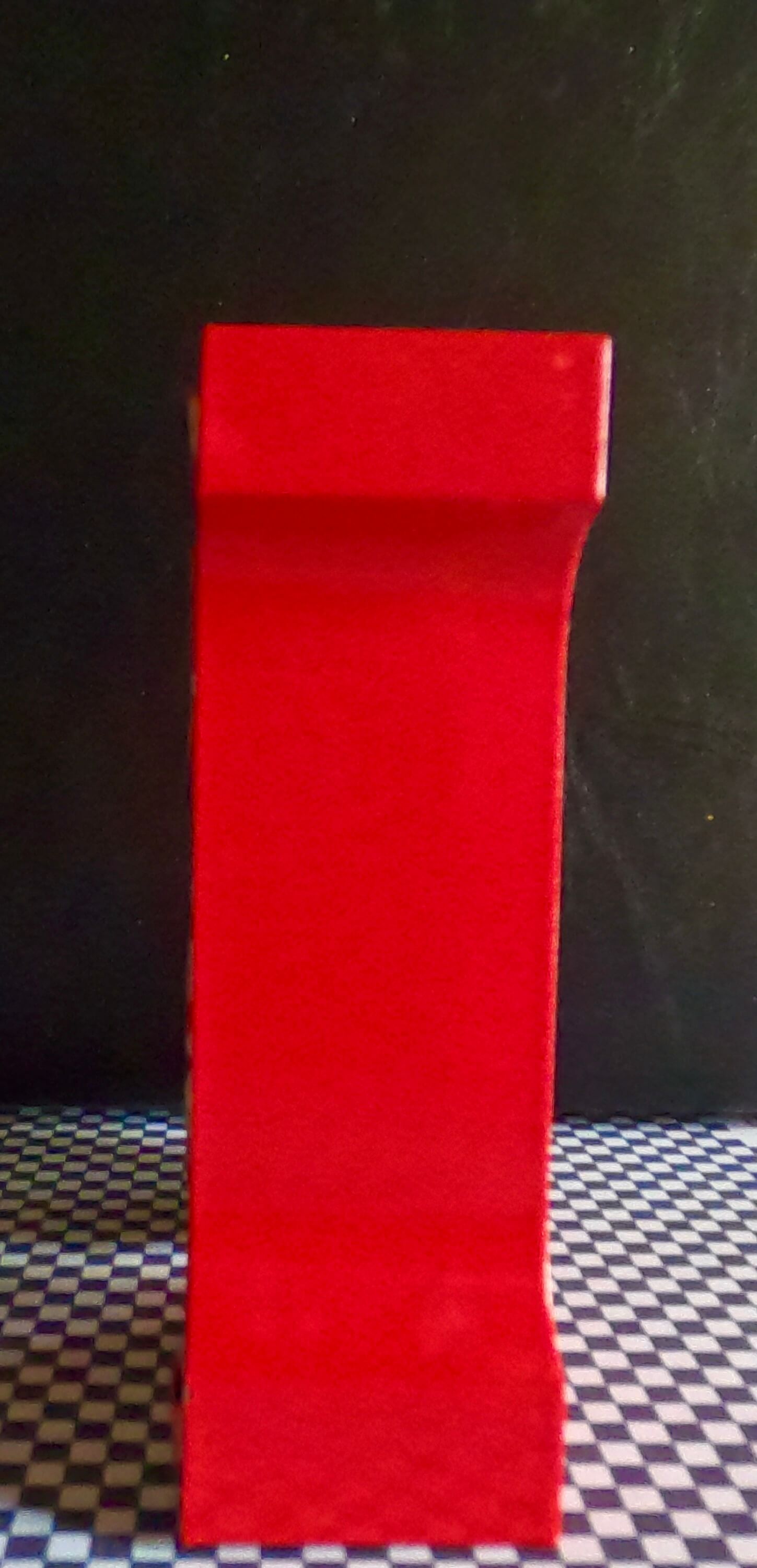
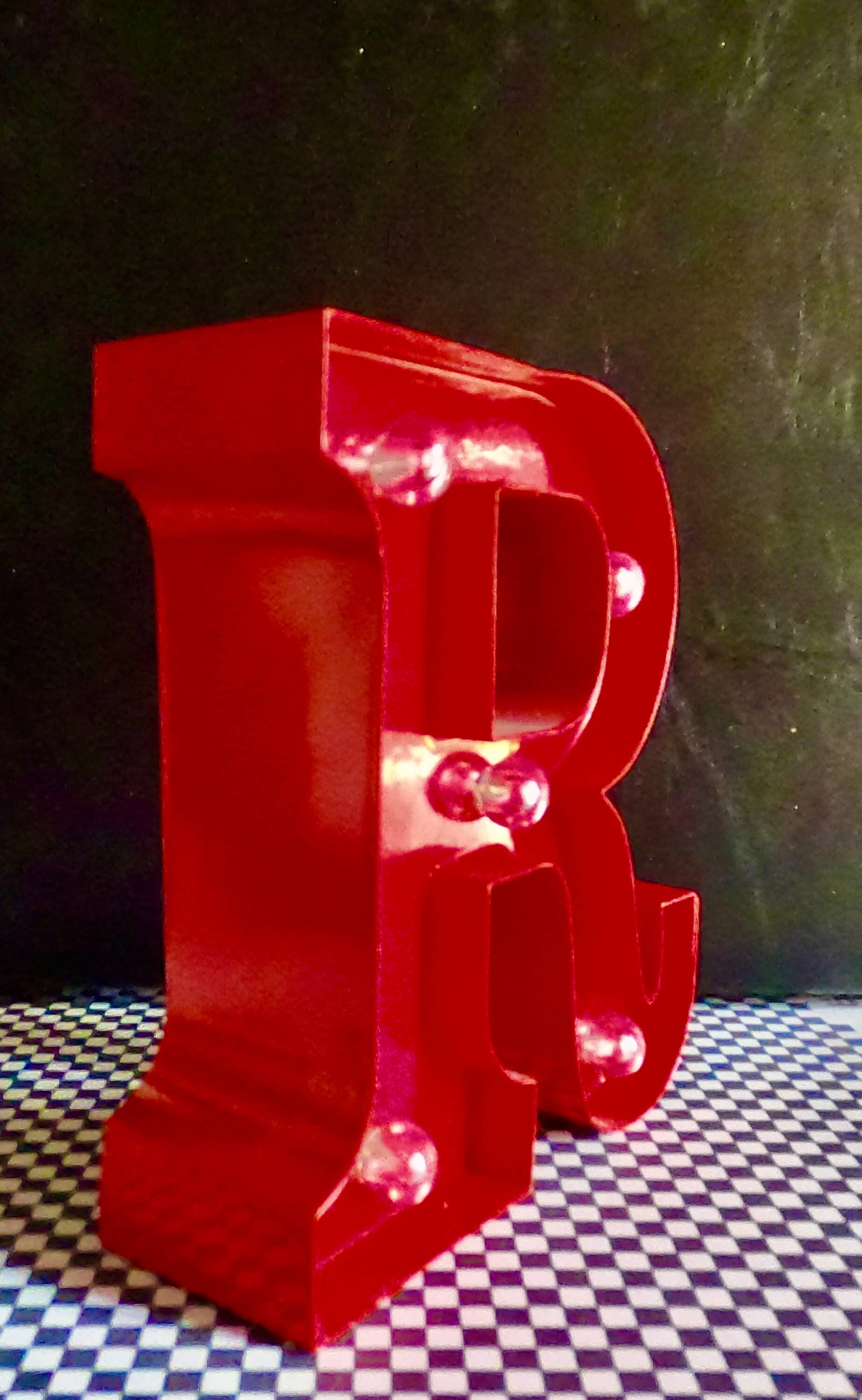
As object of my scan I chose an object of surrender:
a letter "R" that also has small bulbs that can be turned ON or OFF.
|
|
Main Things
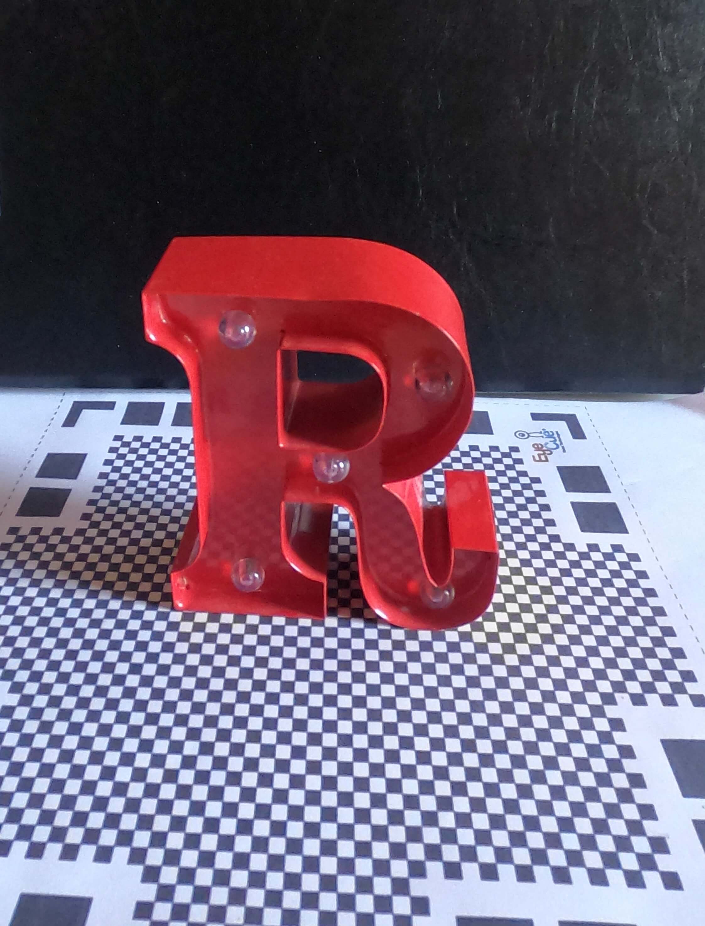
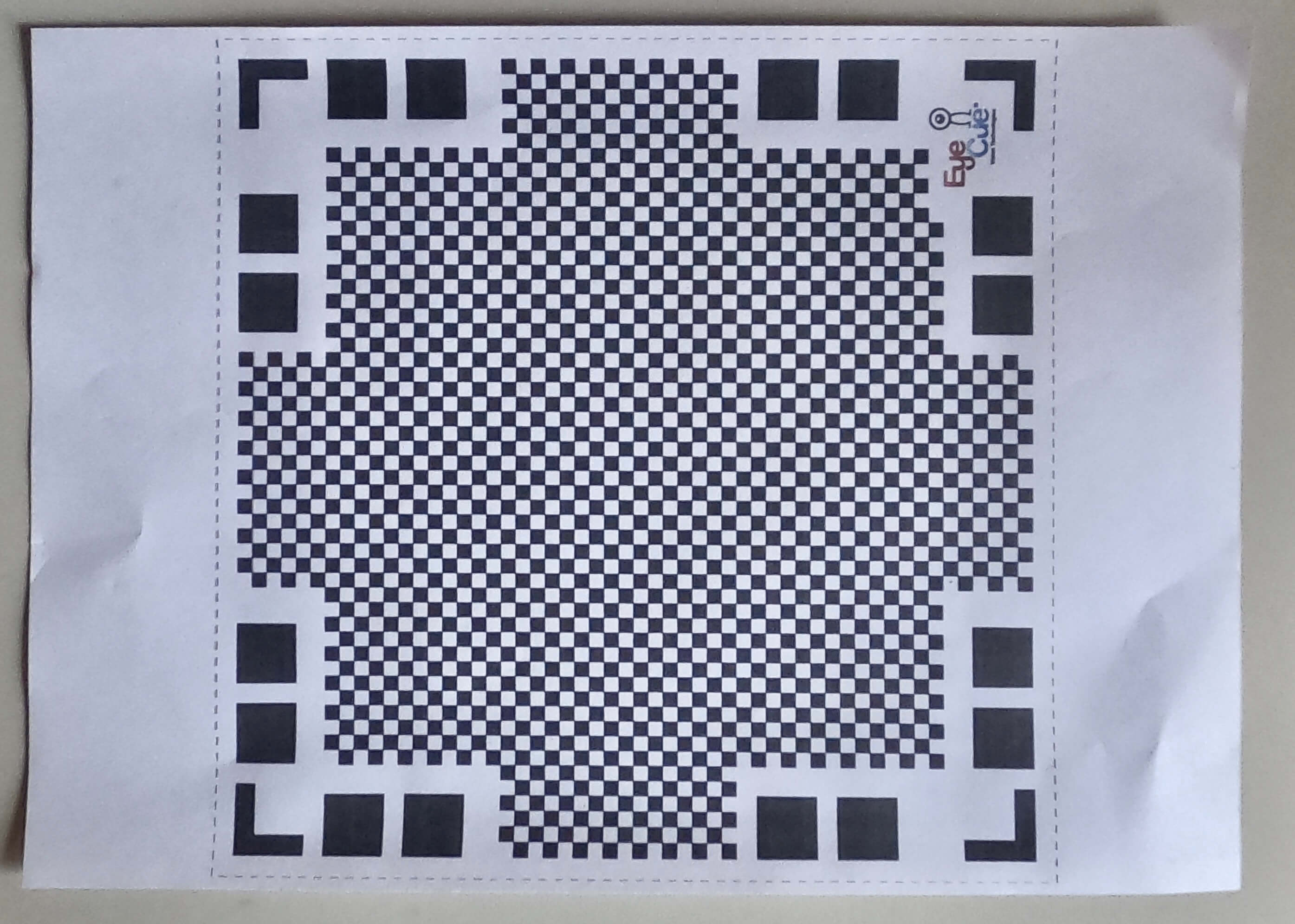
The first step was (as indicated in the tutorial) to print the squared sheet so that the software would detect the position and the area to be scanned. I then placed my object in the center and started to turn around.
|
|
How the 3D Scanning Software Works
Once the scan is finished, the software analyzes all the data: the data are photos taken in different angles that it then puts together to scan the object and shows, turning on itself, the 3D model. In case there are parts that are not very correct, they can be "adjusted" by further scanning the object but in a different position. After checking that everything is correct, you can export it in different formats, I decided to export it in GIF format.
|
|
|
|
|
|
|
|
Design and 3D print an object
WORK FLOW
Idea
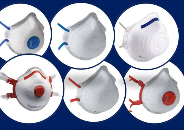
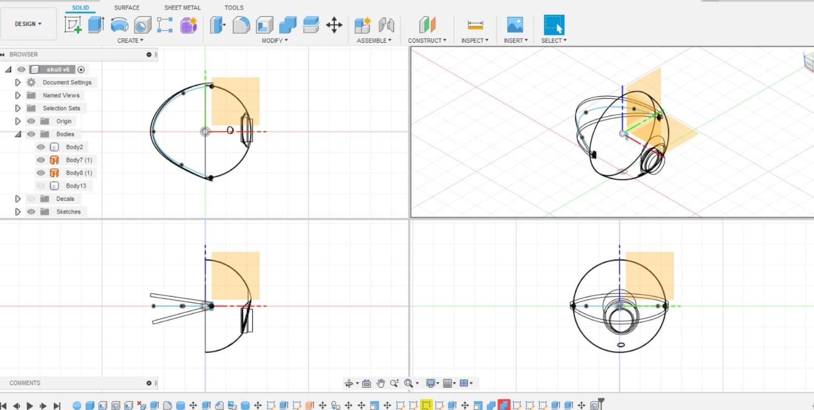
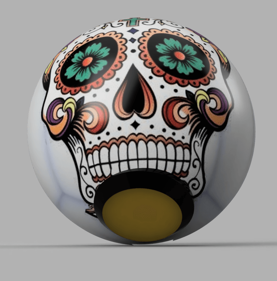
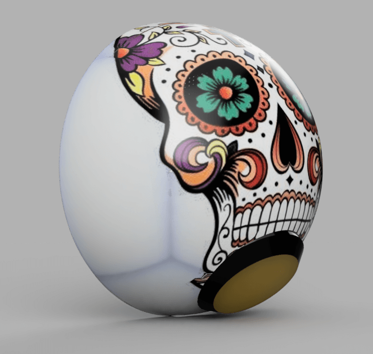
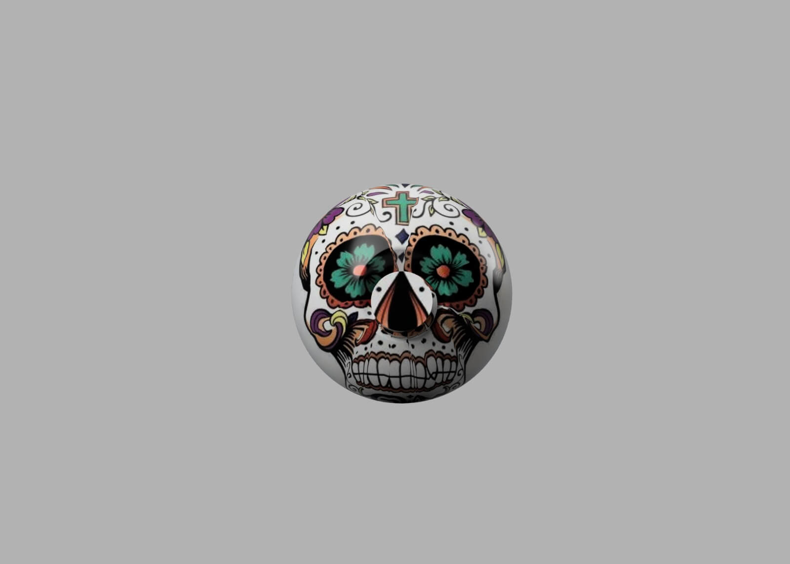
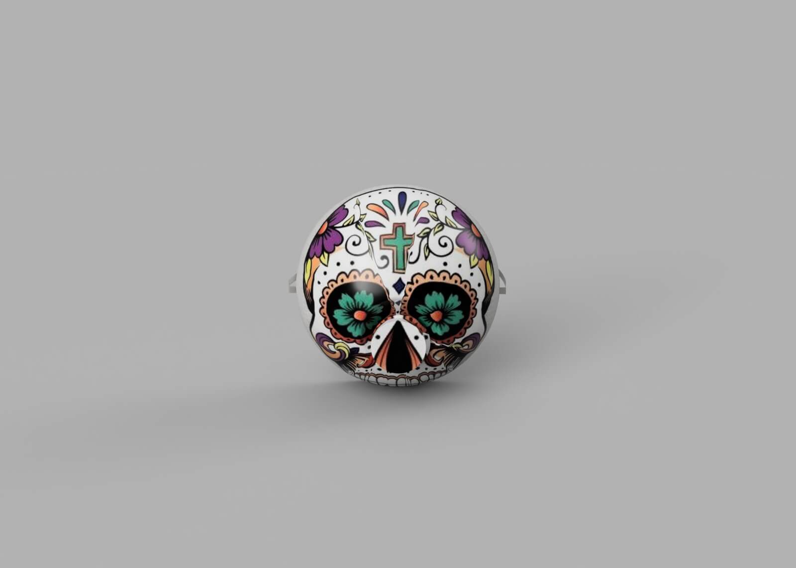
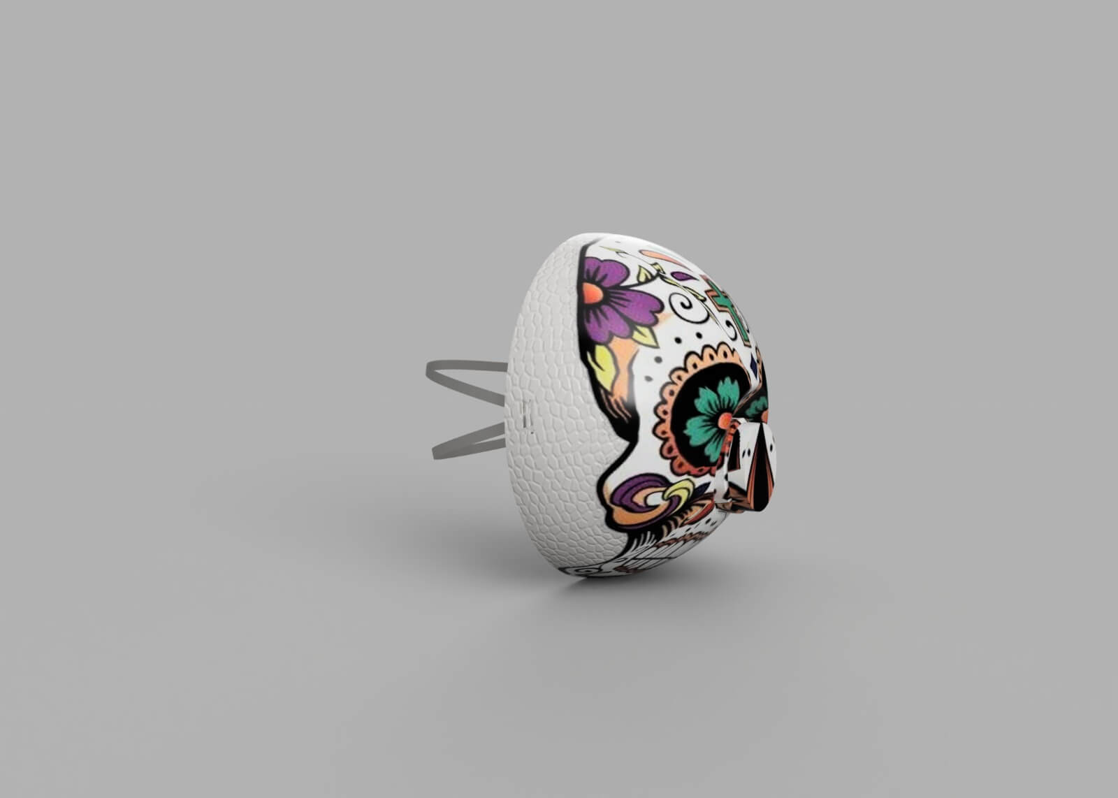
Fusion Mask Design
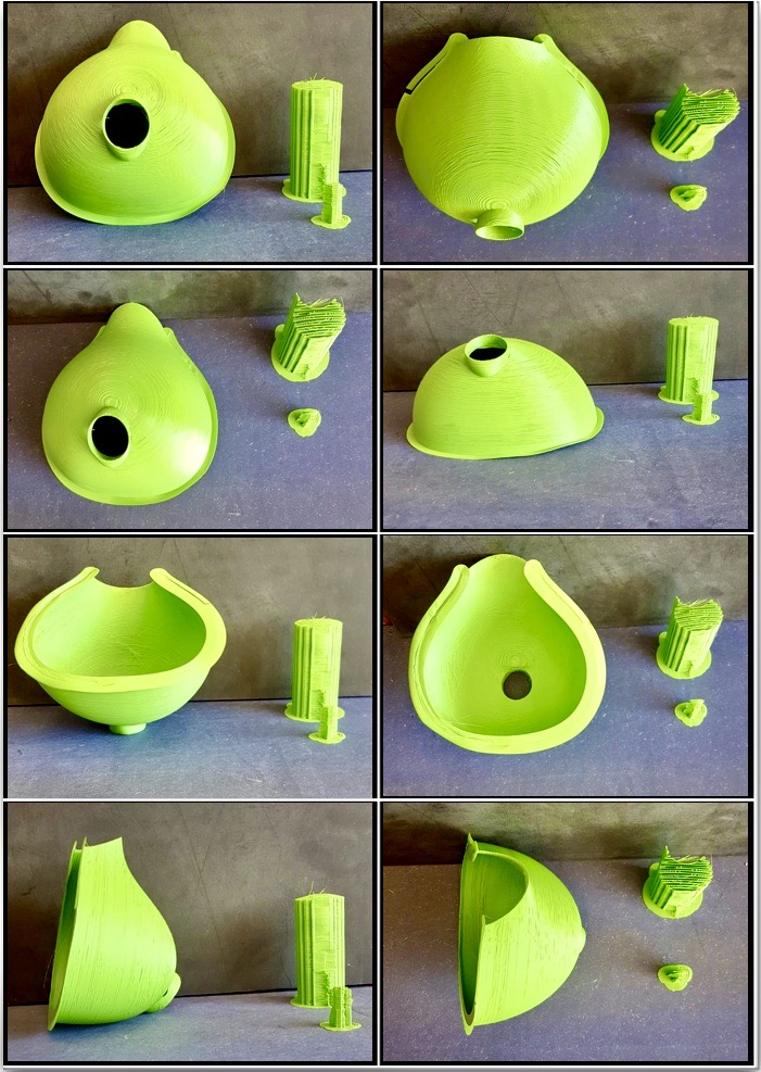
The shape of the mask was obtained from a hemisphere emptied through the SHELL command to which a thickness was then attributed. The next operation was of boolean type with Cylinder subtraction for the filter part and addition of a hollow cylinder. The hemisphere, after the creation of the hole for the cylinder/filter, was pushed slightly inwards to better accommodate, and not make the filter body protrude excessively.
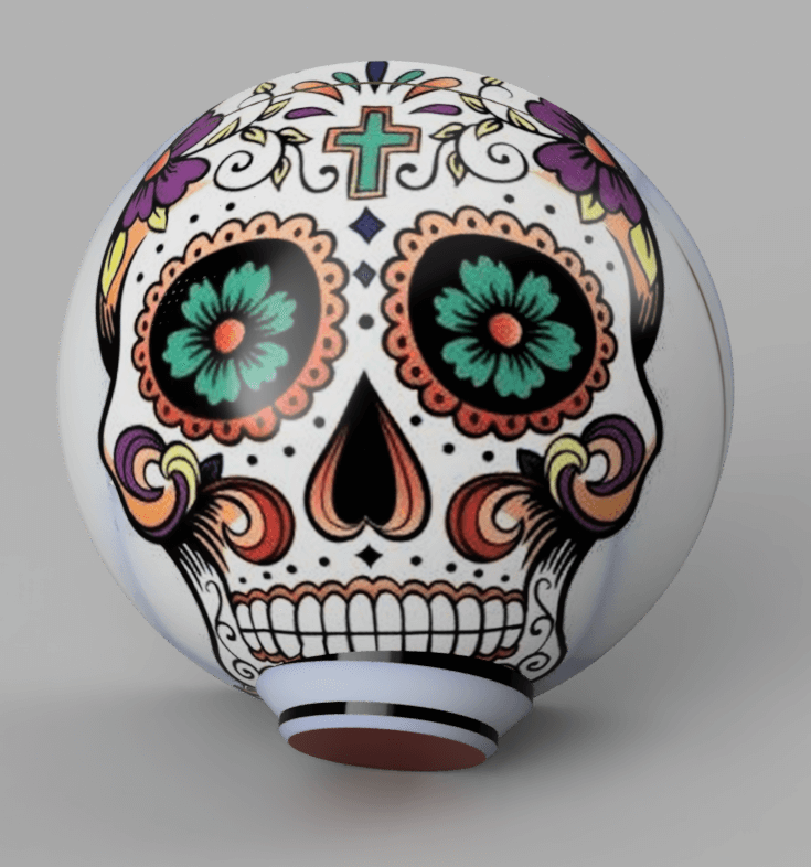
MASK
|
|
|
|
|
|
PRACTICE
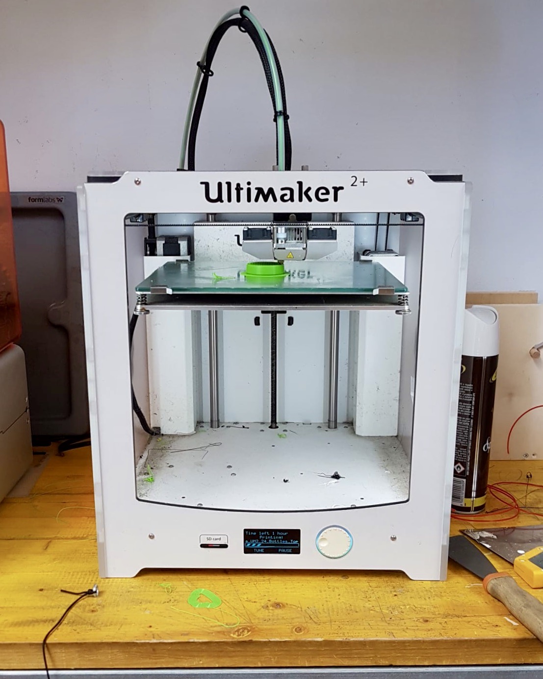
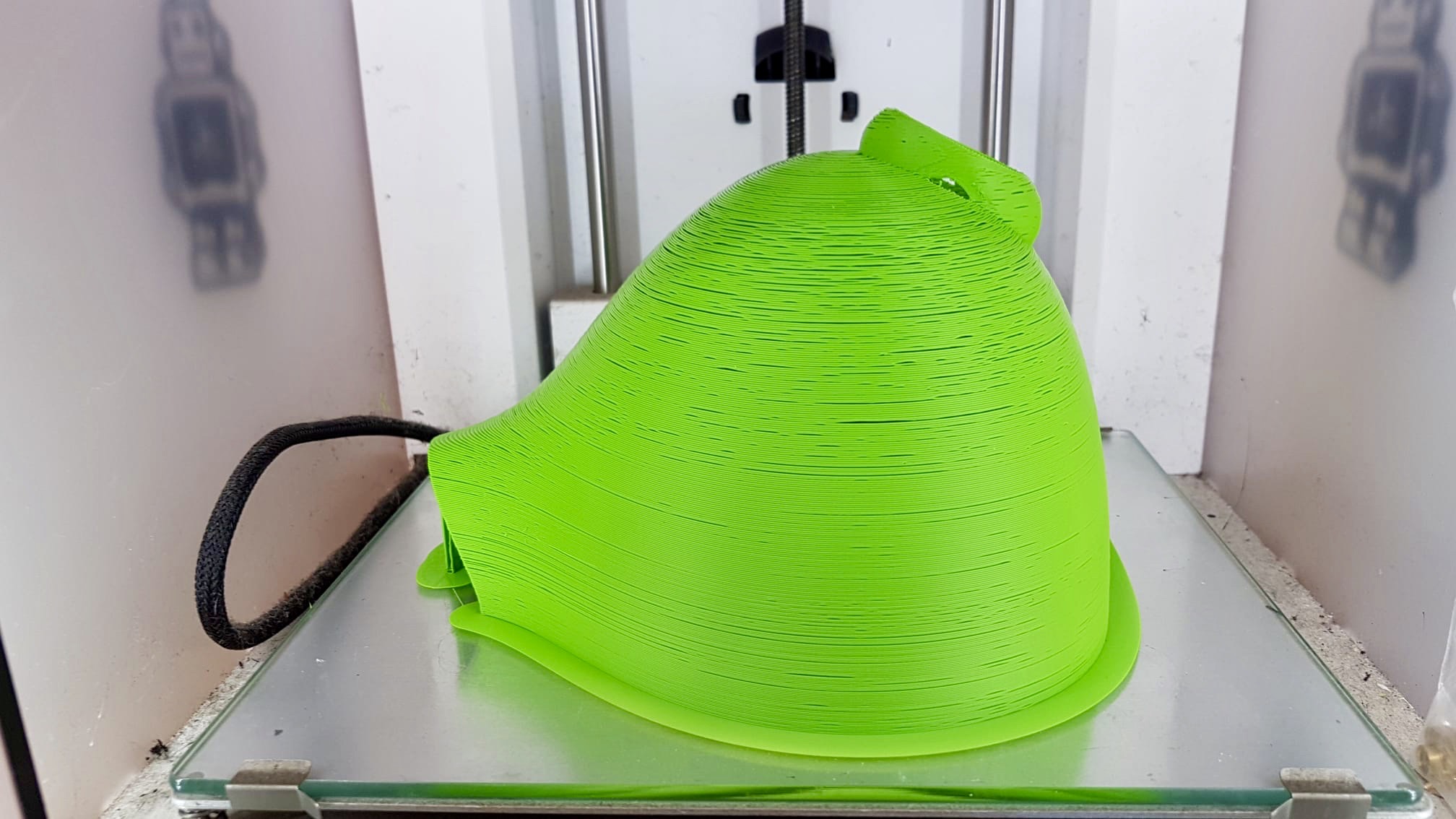
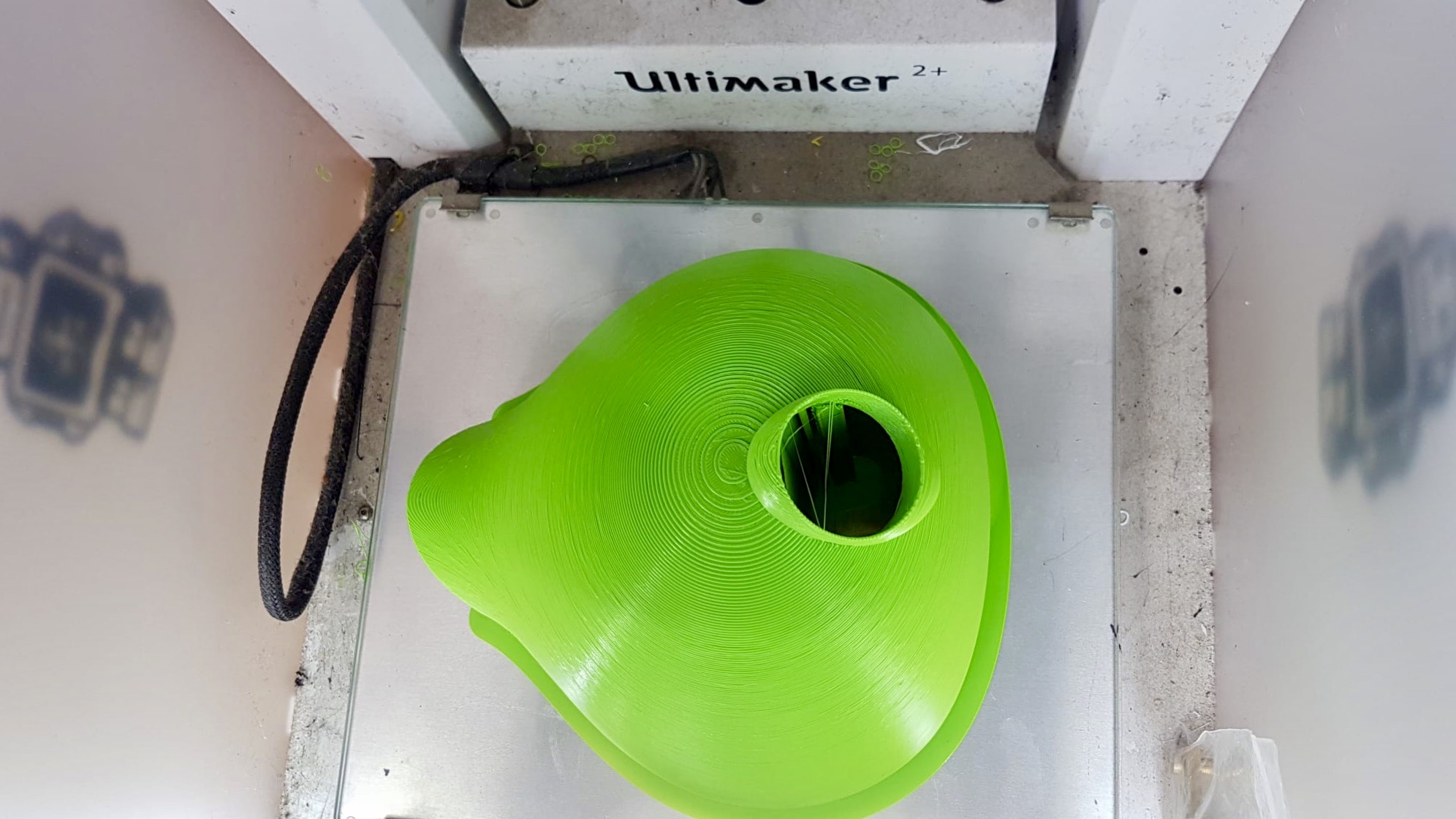
3D Printer - Ultimaker 2+
The first task is to measure and calibrate the object to be printed. After this procedure, I dedicate myself to the 3D printing phase of the mask. The choice of the printer falls on the Ultimaker 2+: I insert my file in STL format (previously exported from Fusion 360) in the Ultimaker Cura Software which allows me to set all the parameters needed for printing. I solve the problem of the construction of the convex part of the mask, which would have static difficulties, by setting inside a support that functions as the supporting structure of the interested part.
|
|
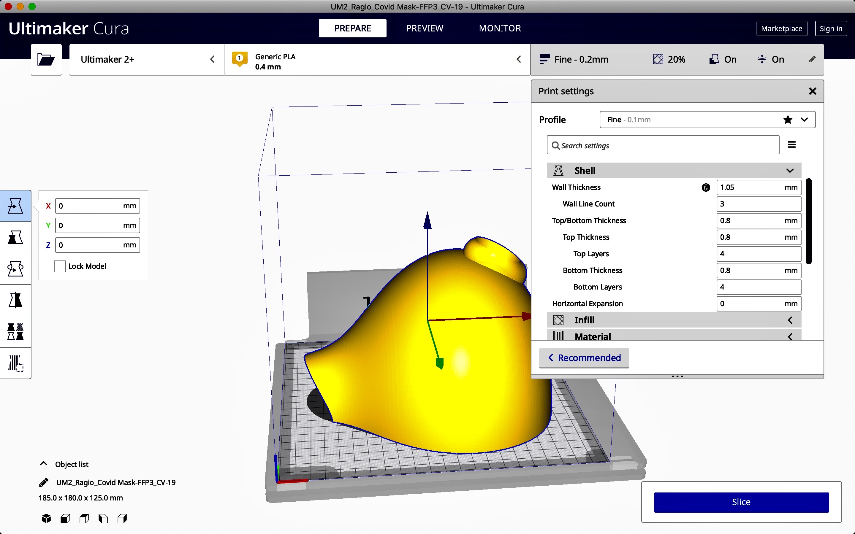
Ultimaker Cura
The parameters have been set. I can go to the verification phase with a preview using the Ultimaker Cura software: in this way I can observe the quality of the final print and the different steps for the realization.
|
|
- MASK STL
SOME THOUGHTS
Can the object you designed also be manufactured using other subtractive techniques?
By having a larger surface, cutting it out and then subtracting the excess parts. This mask is a volume created as a loft, therefore as a sum of surfaces.
It would be difficult but also more time-consuming to make a simple volume (like a sphere) and pass a surface that cuts it. Then subtract the part that is not of interest.
The parameters I use to print the mask are:
- PROFILE: normal
- WALL THICKNESS: 1.05mm
- WALL LINE COUNT 3
- TOP/BOTTOM THICKNESS 0.8mm
- TOP THICKNESS 4
- BOTTOM THICKNESS 0.8mm
- BOTTOM LAYERS 4
- INFILL _LINE_
- DENSITY FILLING 10%
- SUPPORT I put the "tic" and I put a support in contact with the plate
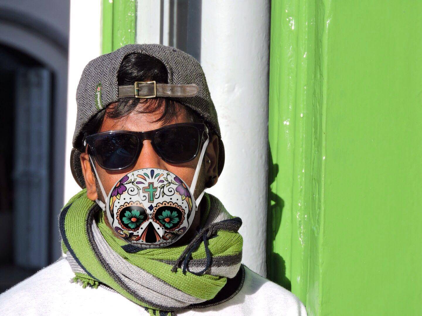
Did you test the mask? Have you worn it for testing? What is your impression of using 3d printing to make this project?
Yes, I have worn the mask to test it and what I can say is that it is not like the ones we normally use. There's no air coming through, except from the "mouthpiece" in front of it.
It must be said, however, that the mask was designed specifically so that the mouthpiece in front of the mask would actually act as a filter for anything that could harm us, whether it's work or an epidemic situation (like this one).
Thinking of it for the future, of course, the filter would be removable so that we could put a filter on it that was suitable for the use we wanted to make of it.
Prepare the object you have scanned to print, add it to Cura and test it. Comment more on the results of the scanning software. Are they good? Bad? What could be corrected to get better results? Add information about your thoughts.
Initially, as we were in the quarantine period due to COVID_19 I used an app on my phone to scan that object and it was very time consuming as a process. (see above how I did the scanning).
In Fab we took out a scanner but unfortunately there was no more software update from the parent company and the scan didn't work. So unfortunately I wasn't able to print out the scan I had done.
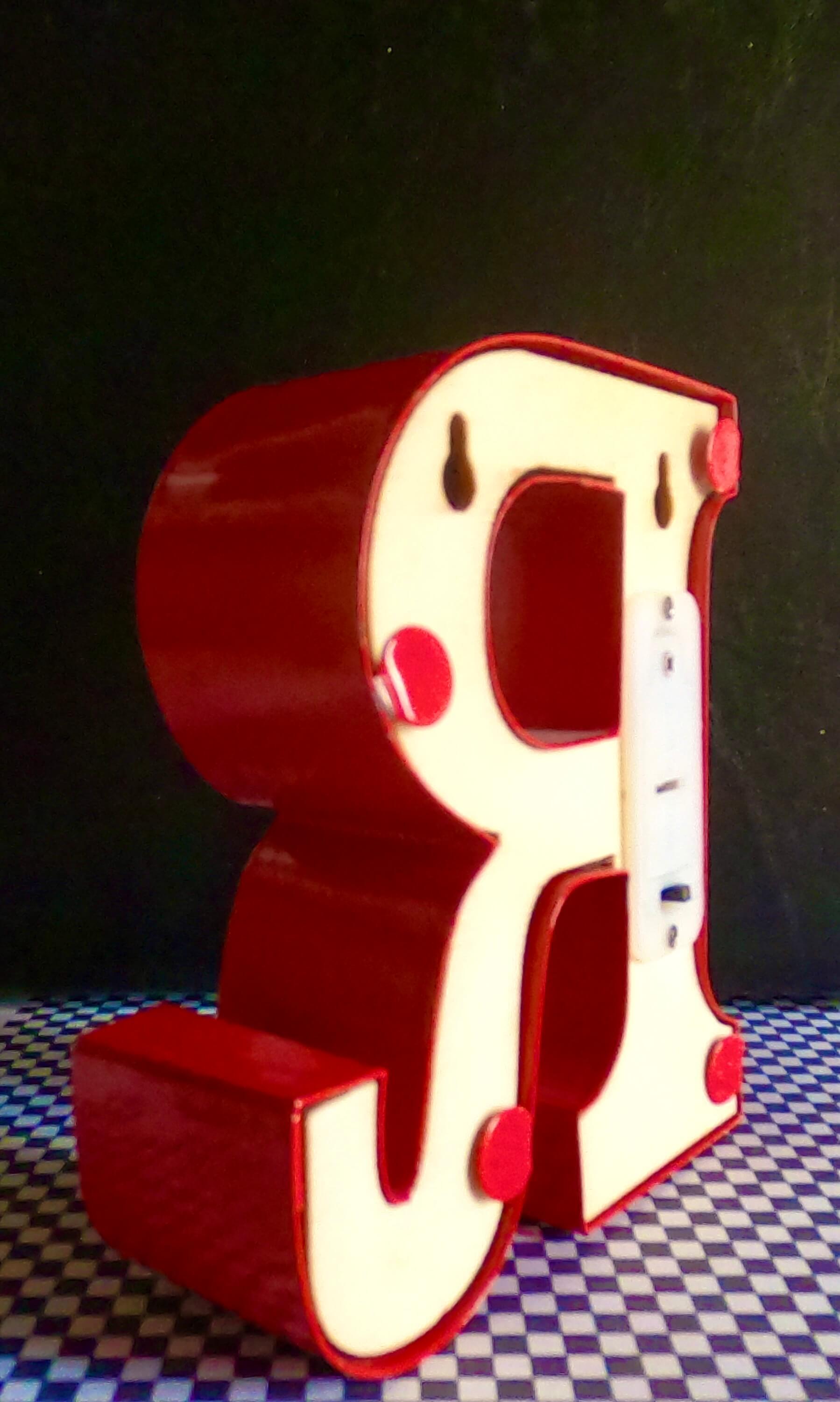
I had made the scan with the application, but as you can see from the photos above, it didn't come out very well, so printing it in 3D would not have been very interesting and easy and I would have wasted only material.
GROUP ASSIGNMENT
Test the design rules for your 3D printer(s);
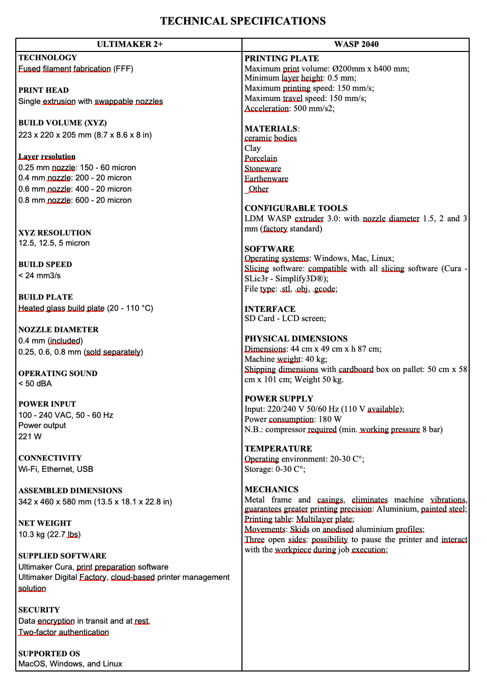
- Ultimaker 2+
- Delta Wasp 2040
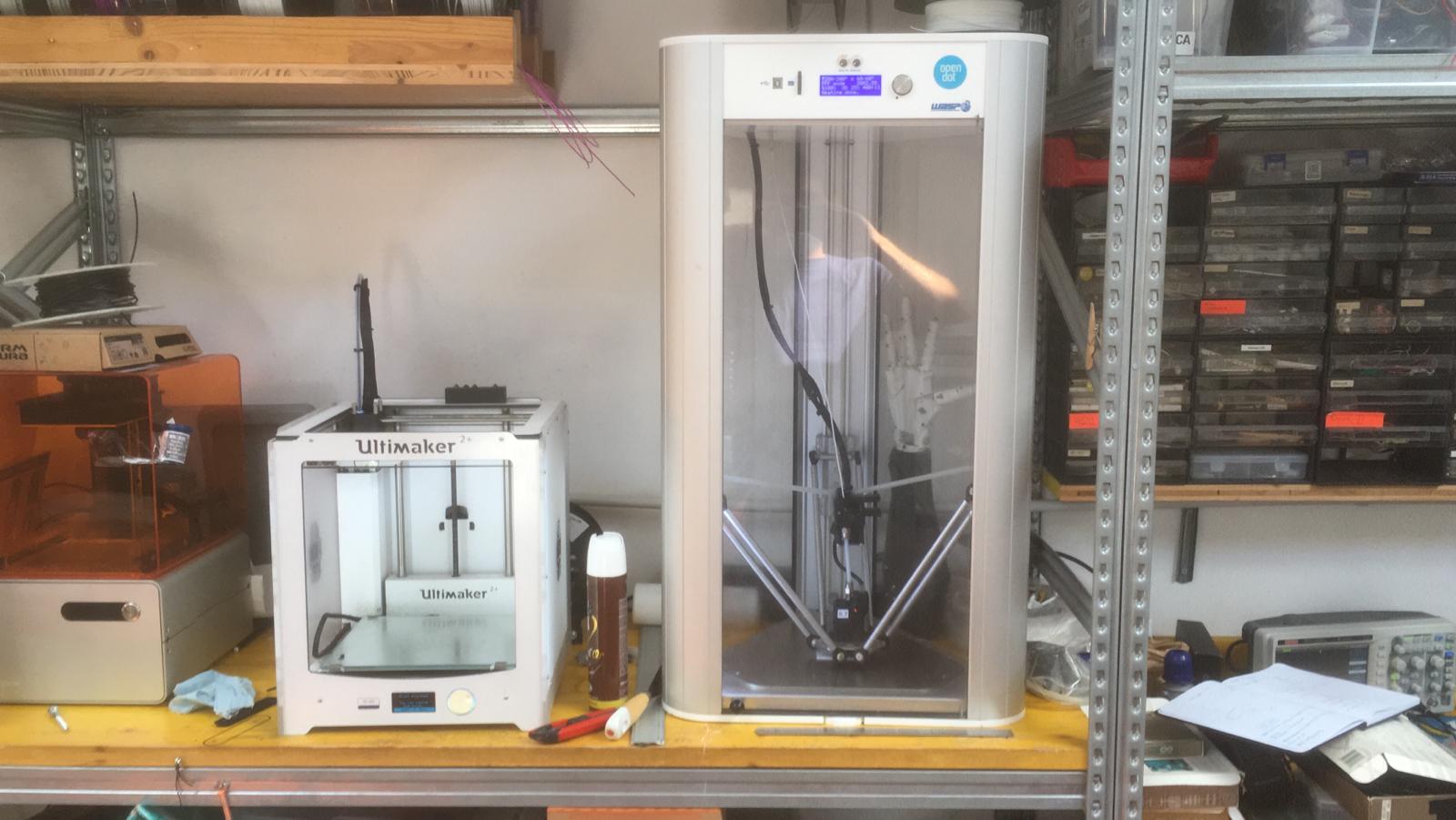
- the Ultimaker moves on 2 axes, while the WASP moves on 3 axes;
- if you want to change the nozzle on the Ultimaker you can change the noozle individually, while on the WASP you have to change the whole body attached to the axes;
the Ultimaker works with 2.85mm filament while the WASP works with 1.75mm filament.
To do this there is a site called THINGIVERSE where you can find examples and projects already done and published that we can download.
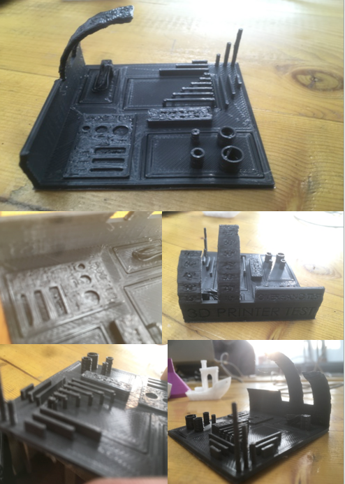
From this site I downloaded the PRINT TEST so that I could better understand how the 3D printer works.
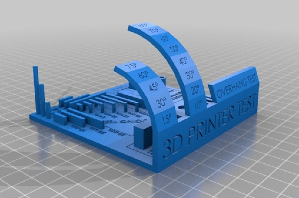
- overhangs at different angles
- bridges at different distances
- holes of various measures
- pipes of various diameters
- towers and walls
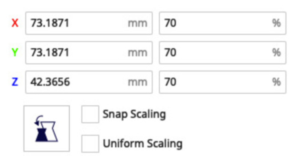
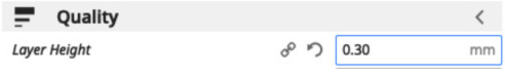
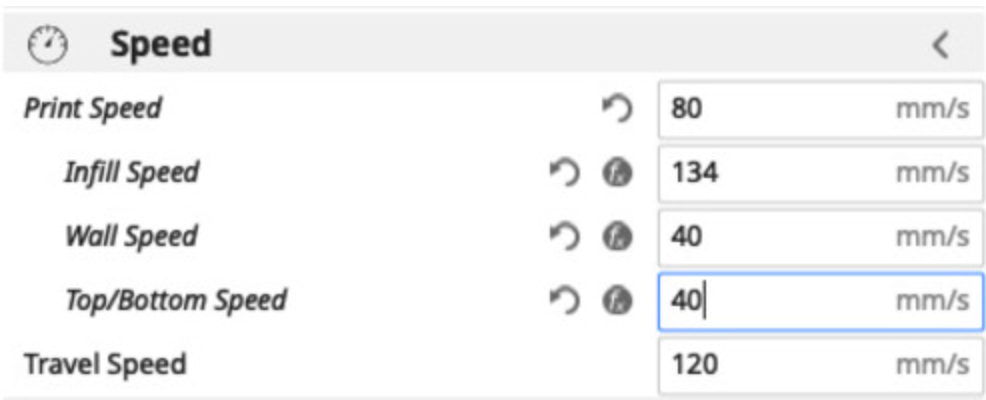
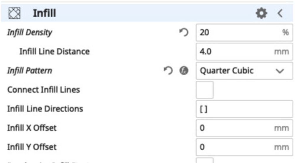
In order to save time I chose a series of options on Ultimaker Cura designed to finish the model quicker:
Once the scan is finished, the software analyzes all the data: the data are photos taken in different angles that it then puts together to scan the object and shows, turning on itself, the 3D model. In case there are parts that are not very correct, they can be "adjusted" by further scanning the object but in a different position. After checking that everything is correct, you can export it in different formats, I decided to export it in GIF format.
|
|
|
|

|

|
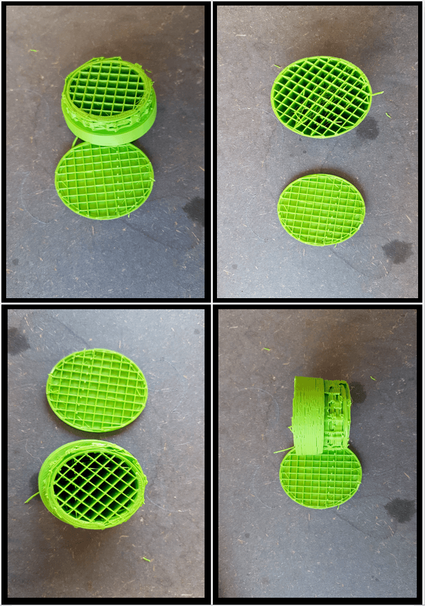
Even with such settings:
- Overhangs were printed with no problems up untill 55°
- Bridges, walls and towers did not present problems
- The diameters were respected, with the sole difference of small filament residues in the larger ones
- Circular holes did not present problems
- Elliptic holes tended to “close up” at the extremities of the smaller ones
- The typography did not came out properly (mainly because of the downscaling)
- The unsupported bracket fully failed
To see the printing process go to WEEK_5 in my repository under "PRACTICE" and