Networking and Communications
ASSIGNMENT
Individual Assignemnt
Design and build a wired &/or wireless network connecting at least two processors
Group assignment
Send a message between two projects
Introduction
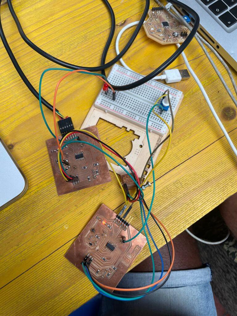
By always using the boards I have made WEEK_4 I make my boards communicate with each other and with my PC.
To do this I need:
- My two boards
- My programmer
- One BreakBoard
- Jumpers
- Led
- Potentiometer
- 330ohm res
By always using the boards I have made WEEK_4 I make my boards communicate with each other and with my PC.
|
|
WHAT IT IS i2C ?
is a communication protocol between two Microcontrollers
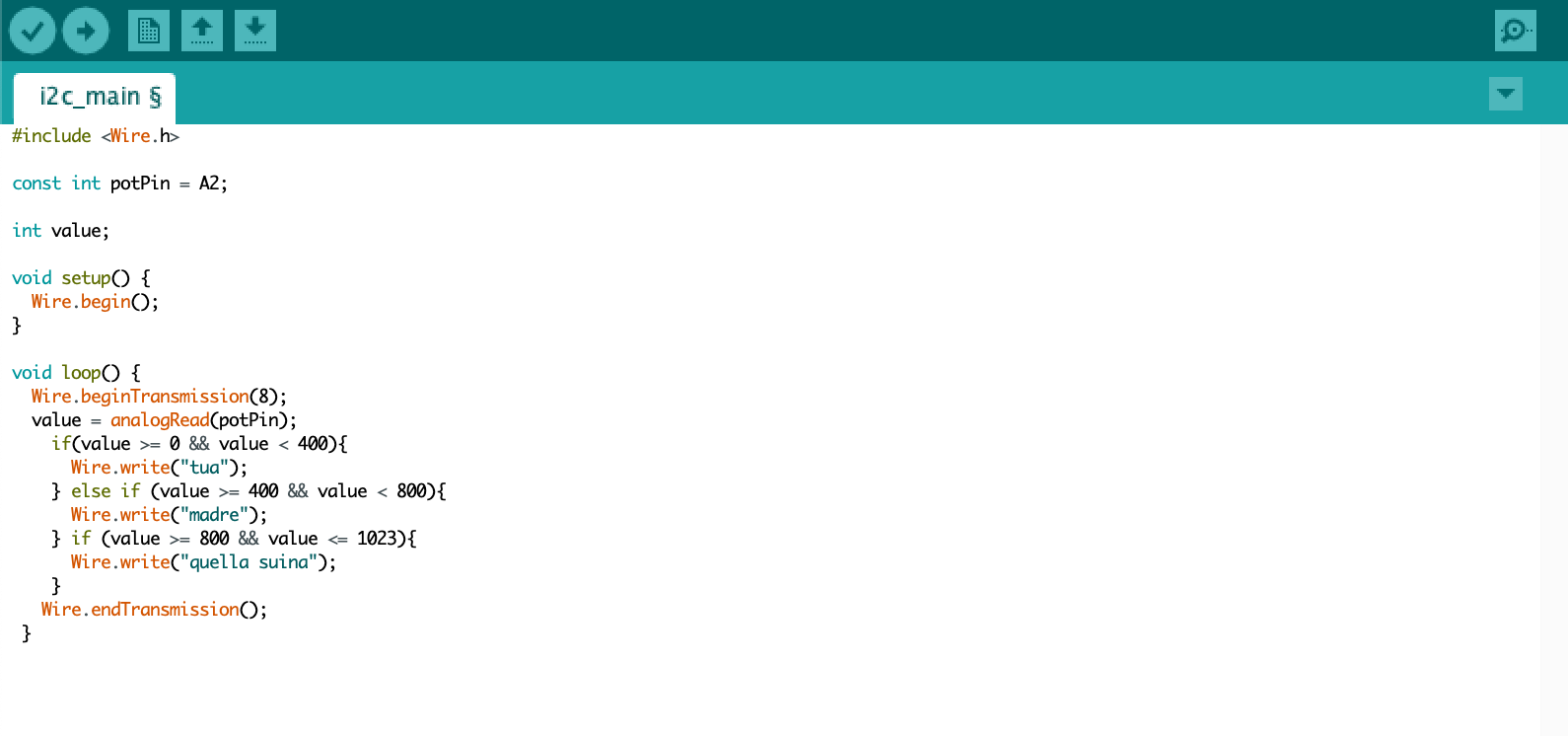
WHAT I DID WITH i2C_Main BOARD
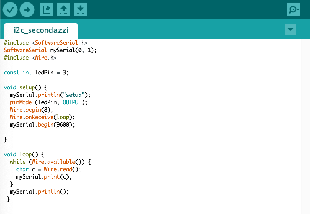
On a board I have divided a value of the potentiometer into 3 bands depending on these bands was read by the potentiometer sent a wire message to my secondary board (i2C_SECONDAZZI) that spoke through serial communication to my computer the string received.
FILE
- i2C_SECONDAZZI
- BOARD
- SCHEMATIC
where did I find the information I needed to understand all this?
In order to understand how to make the two boards work and how to make them communicate with each other, I read some online explanations found on the sparkfun website(link)
Here are some of the parts that I think are most important:
I chose to use the Inter-Integrated Circuit (I2C) protocol, which allows multiple digital "peripheral" integrated circuits ("chips") to communicate with one or more "controller" chips.
- like the Serial Peripheral Interface (SPI), is intended exclusively for short-distance communication within a single device.
- like asynchronous serial interfaces (such as RS-232 or UART), it requires only two signal cables to exchange information
- but do not have the limitations of RS-232 and SPI
RS-232 serial
- they are asynchronous (no clock data is transmitted), and the devices using them must also have clocks close to the same frequency and not vary to avoid communication errors;
- require additional hardware: the UART at both ends is relatively complex to implement accurately in software, and this affects data rates;
- are inherently suitable for optimal communication between two and only two devices.
transmission speed is relatively low;
SPI
- require a larger number of pins;
- the large number of connections for each device can make signal routing more difficult in situations of restricted PCB layout.;
- SPI only allows one controller on the bus;
I2C - the best of both worlds
- I2C requires only two wires, like asynchronous serial, but those two wires can support up to 1008 peripheral devices;
- unlike SPI, I2C can support a multi-controller system;
- one extra bit of metadata must be transmitted (the "ACK/NACK" bit);
- the hardware required to implement I2C is more complex than SPI, but less so than asynchronous serial;
- it can be implemented very simply in software;
I2C at hardware level
- Signals;
- Each I2C bus consists of two signals: SCL and SDA;
- SCL is the clock signal and SDA is the data signal;
- The clock signal is always generated by the current bus controller; some peripheral devices may force the clock low at times to delay the controller from sending more data (or to take longer to prepare the data before the controller attempts to synchronise it). This is called "clock stretching";
- Unlike UART or SPI connections, I2C bus drivers are "open drain". which means that they can lower the corresponding signal line, but cannot drive it up. Therefore, there can be no conflict on the bus where one device tries to drive the line up while another tries to drive it down, eliminating the risk of driver damage or excessive power dissipation in the system. Each signal line has a pull-up resistor on it, to restore the signal high when no device is asserting it low;
Logical signal levels
- Because the devices on the bus do not actually drive the signals high, I2C allows some flexibility in connecting devices with different I/O voltages;
- In general, in a system where one device is at a higher voltage than another, it may be possible to connect the two devices via I2C without any level-shifting circuitry between them;
- The trick is to connect the pull-up resistors to the lower of the two voltages. This only works in some cases, where the lower of the two system voltages exceeds the higher-level input voltage of the higher voltage system, e.g. a 5 V Arduino and a 3.3 V accelerometer. Depending on the design of the Arduino or I2C, it is recommended to use a logic level converter to be consistent and avoid damaging any devices on the busl;
- If the voltage difference between the two systems is too large (e.g. 5 V and 2.5 V), a simple I2C level shift card can be used. This dedicated level-shift card also includes an enable line, and can be used to disable communications to selected devices. This is useful in cases where more than one device with the same address needs to be connected to a single controller: Wii Nunchucks are an example of this;
- Unlike UART or SPI connections, I2C bus drivers are "open drain". which means that they can lower the corresponding signal line, but cannot drive it up. Therefore, there can be no conflict on the bus where one device tries to drive the line up while another tries to drive it down, eliminating the risk of driver damage or excessive power dissipation in the system. Each signal line has a pull-up resistor on it, to restore the signal high when no device is asserting it low;
- There are also bi-directional logic level converters that can be used;
Protocol
Communication via I2C is more complex than a UART or SPI solution. Signalling must respect a certain protocol for the devices on the bus in order for I2C communications to be recognised as valid. Fortunately, most devices take care of these aspects, allowing you to concentrate on the data you wish to exchange.
Data frames
- After the address frame has been sent, data can begin to be transmitted. The controller will simply continue to generate clock pulses at regular intervals and the data will be placed on SDA by the controller or peripheral, depending on whether the R/W bit indicates a read or write operation. The number of data frames is arbitrary and most peripheral devices will automatically increment the internal register, meaning that subsequent reads or writes will come from the next register in line;
- Repeated boot conditions;
- Sometimes it is important that a controller can exchange several messages at once, without other controllers on the bus interfering;
- For this reason the repeated start condition has been defined;
- To perform a repeated boot, SDA is allowed to rise while SCL is low, SCL is allowed to rise and then SDA is lowered again while SCL is high;
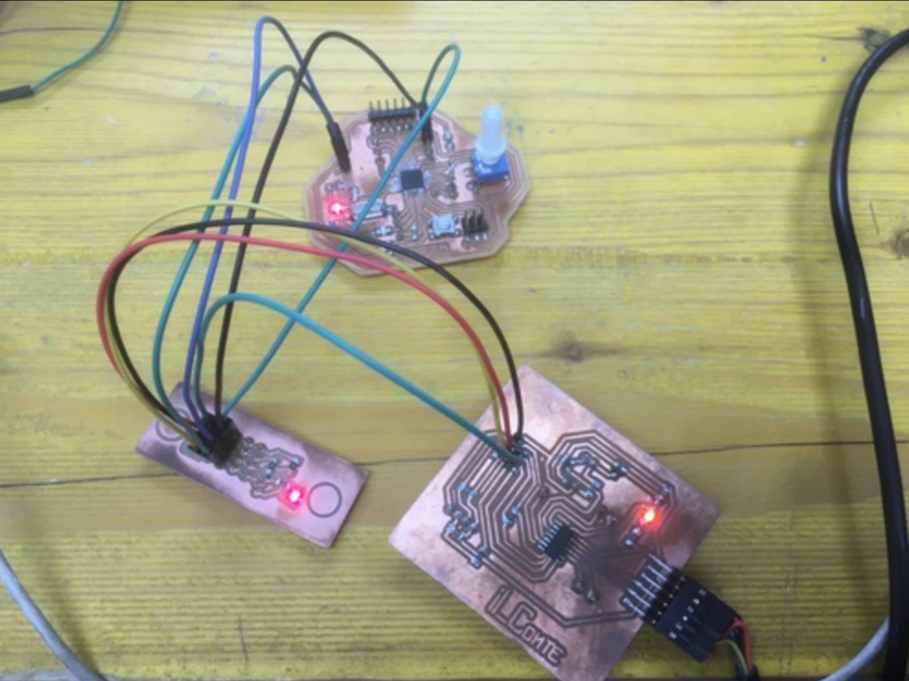
GROUP ASSIGNMENT
As group assignment for this week we wrote two new sketches in order to have one of my boards and one of Filippo‘s boards to network in i2c.
His board would be the secondary, mine the main one. The secondary board receives values from the main board and communicates them via serial communication to my laptop. The main board would read it’s potentiometre value and send it to the other board.
FILE