A10 - Input Devices
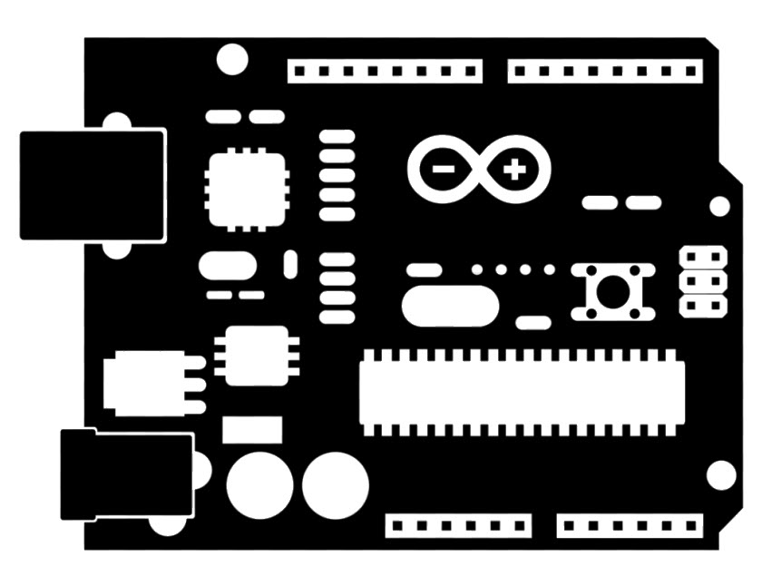
Because I don´t have access to the Fab Lab in México City due to the COVID, I´m still not been able to construct my PCB board, that´s because I´m going to use a Arduino Board to test the Input Devices.
This definitions are extracted are extracted an modified from the Arduino section of the book "Algorithms for Visual Design" - Using the Processing Language from the Autor Kostas Terzidis
Physical Computing
Physical Computing is a term used to denote the use of physical devices to carry out computational processes.
- Kostas Terzidis / Algorithms for Visual Design

Sensors
Sensors are devices that capture information on the environment and measure or sence it. One general clasification of sensors is if they are analog or digital.
#### Analog Analog sensors return variations of "On or Off" states, as in a button if it is pressed or not.
I find a very interesting history of the icon of "On and Off". The symbol represents the two states of the current flow or the básic logic states, in binary "O" means negative or not recieving current and "1" that representas positive or that current it´s flowing.
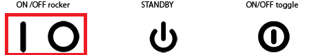
Origin of the icon "On - Off"
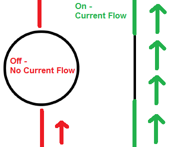
"On - Off" diagram of current energy flow
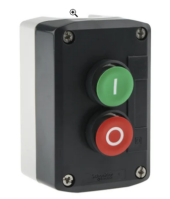
"On - Off" button
Digital
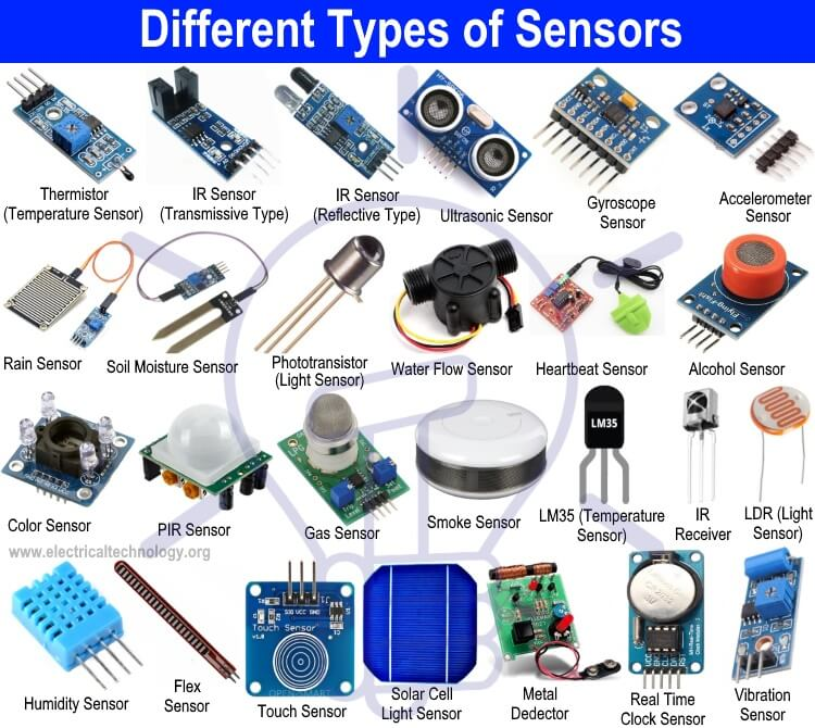
Digital sensors return a series of variations or spectrum of data as a spectrum of options as a the value of a dial positions.
This is some examples of sensors.
Actuators
 Actuators are devices that produce an action in the environment, like a LED that lights, a Servo motor that Spins or a speaker that makes sound.
                   Types of Actuators
  Electric Linear
  Electric Rotary
  Fluid Power Linear
  Fluid Power Rotary
  Linear Chain Actuators
  Manual Linear
  Manual Rotary

Microcontroller
The microcontroller board is a computing device that performs logical or analytical operations as well allows the "Input" or "Output" of information captured by the sensors or actuators.
The basics of Electric Circuits
Electricity is the flow of electrons in a medium like copper or tin, the direction in witch the electrons flow are by convention the positive direction or pole on a motor. The "electrons" carry the charges and the protons carries the positive charges in the nucleus of an atom.
Current is defined as the number of electrons that passes trough a medium per second. I is the convention symbol and it´s measured in amperes.
1 amp = 6.28 x 10¹⁸ electrons per seconds.
Because its common to utilize large figures of numbers is common to use mA or milliamperes.
1 mA = 1/1,000 amp
Voltage is the potential to transport constant electrons trough a medium, the conventional symbol is V and it´s measured in volts.
A resistor is a device that slow down the flow of the electrons, the conventional symbol is "R" and its measured in ohms, the Greek letter for ohm is the omega letter Ω. In battery-based electrical circuits the quantities are usually very small and it´s very common to use kΩ (1,000 ohms) or MΩ (1,000,000 ohms).
The resistors can be identified by a color system and order of the three strips on their body beginning with the gold stripe on the right side.
![Type of Sensors] (2021-04-07.assets/resistor.jpg)
The "Ohms Law" is the relationship between the current, voltage and resistance.
Ohm´s Law
*V = I * R* or *I = V/R* or *R = V/I*
This means that the product of the current and resistance is equal to the voltage, as the resistance increase or decrees, the current increases or decreases at the same time.
A Capacitor is a device that stores the electrons in the flow of a circuit. It´s measured in farads and the convention symbol it´s F. In battery-based electrical circuits the quantities are usually very large and it´s very common to use Ω (1,000 ohms) or MΩ (1,000,000 ohms).
We can think of it as a tank of electrons, that helps stabilize the current flow or count the time that it takes to fill.
Time = Capacity * Resistance
Arduino as Neil said is a Open Source, Physicals Computer workflow that uses a programming language based on C++, a set of hardware or software libraries, and a set of different controller boards with different applications.
The firs thing was to download and install the Arduino Software and check if it the Arduino board was working properly with a simple LED to check if a LED Blinks. I connect directly the LED to the Ground Pin and to the 13° pin of the Digital Output of the Arduino Uno board, and upload the "Blink" Arduino example file.
This is the basic "Blink" code that comes in the Arduino examples files.
Basic Blink
Fire Sensor
LED Button - Color
Smoke Sensor
Checklist
Input Devices
The second half of the Fab Academy program is designed to build on the previous weeks. You will be synthesizing information and implementing skills that you were introduced to in the first half of the programme and encouraged to integrate these into your final project proposal.
Group assignment Probe an input device(s)'s analog and digital signals Document your work (in a group or individually)
Individual assignment Measure something: add a sensor to a microcontroller board that you have designed and read it. Learning outcomes
- [ ] Demonstrate workflows used in sensing something with input device(s) and MCU board
Have you?
- [ ] Linked to the group assignment page
- [ ] Documented what you learned from interfacing an input device(s) to microcontroller and how the physical property relates to the measured results
- [ ] Documented your design and fabrication process or linked to previous examples.
- [ ] Explained the programming process/es you used
- [ ] Explained problems and how you fixed them
- [ ] Included original design files and source code
- [ ] Included a ‘hero shot/video’ of your board
FAQ What does "probe" mean? Answer: A test probe is a physical device used to connect electronic test equipment to a device under test (DUT). To probe means to measure, observe or monitor signals with test probes.
Is the satsha kit/fabduino I fabricated considered a valid board for this assignment? Answer: Fabricating an unmodified board is considered as electronics production. It doesn't count towards any design skill. You must make some significant changes to the original satsha kit/fabduino, for the board to be considered your own design.
Can I use a breadboard and/or jump wires to interface my input device(s) Answer: No. You can't use a breadboard. If you use wires, they must be soldered or connected with connectors.