A7 - Computer Controlled Machining
A 7.2- Make (design+mill+assemble) something big
Desk Station (Multiple Propose and Position Desk)
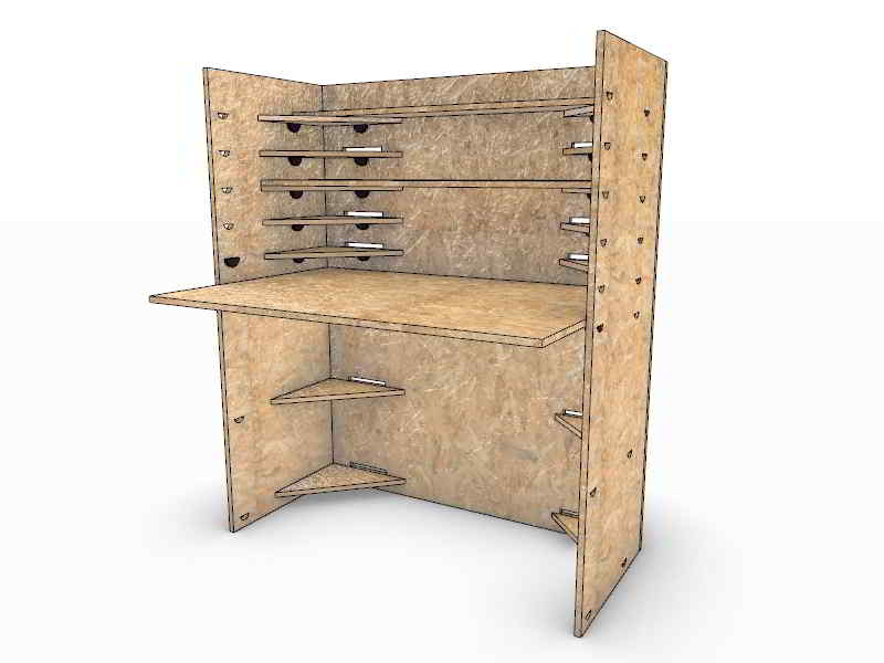
Render
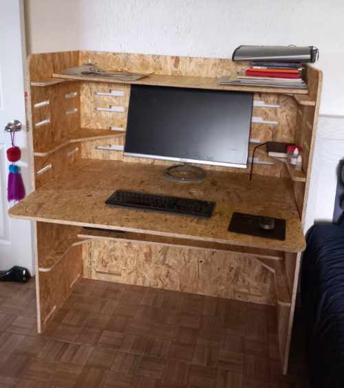
Final Product
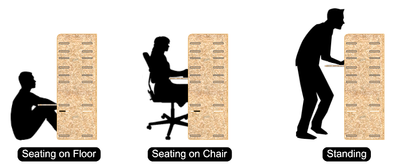
I designed a Multy-Position Desk that allows the user to work in different positions, you can use it seating in the floor, seating in a chair or standing. I hope the help my back because I spend many hours seating in front of the computer, building or fixing something.
I began with the measurements of the main areas I like to work. I specify the main work area for a Laptop or machine that I´m going to work on, I also measure a place for storage, a zone for a mouse or Wacom, a place to put your book for reading, and two drawing or writing areas.

The result its a small Flat Pack Modular Desk that you can stack side by side depending on what your working on.
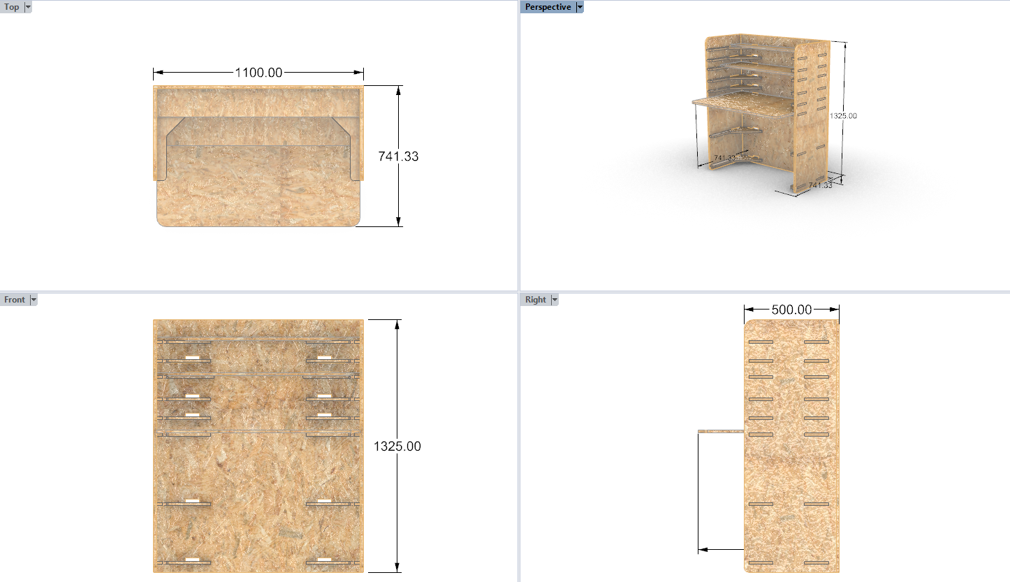
Orthogonal Views
Explosive

Nested Pieces
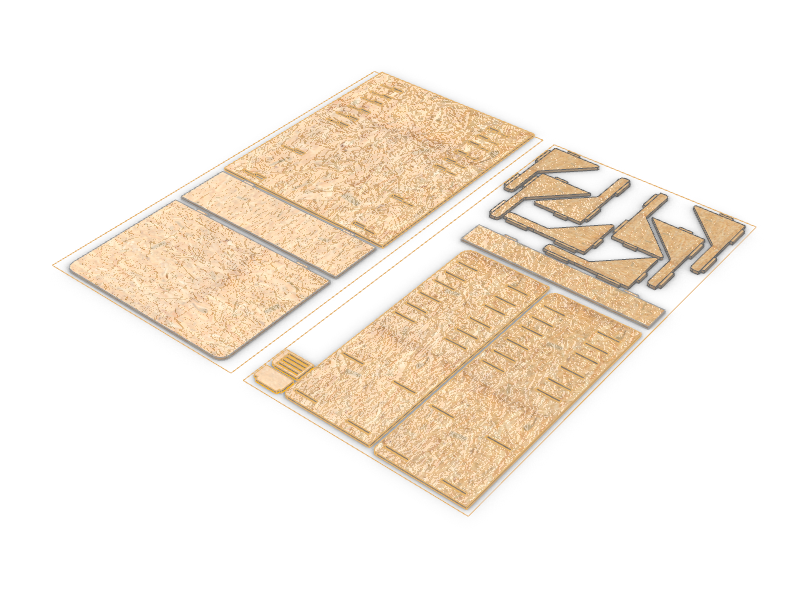
The Cutting Process
I´m using a OSB 15 mm board.
For my box stock I use 2400 x 1440 x 16 mm.
I use a 1/8" Flat End Mill. Each for cutting, in Z axis the cutting step was 3 mm so I have to make it pass 3 times
After a year I was able to send my files to the CNC machines at the FabLab.
The first thing is to start the CNC Machine and wait for it to get warm.
Homing
Before homing the machine I follow this small check list:
-
Check were are the emergency switches.
-
The cutting surface has to be clean.
-
All the surrounding of the machine has to be clear.
After checking that all was clear I procced to Home the machine with the F9 function command in the control of the router.
Then I assign the sacrifice material height with the F10 (CHECAR) function command
And finally I send the layer to the global Home with the F13 (CHECAR) function command
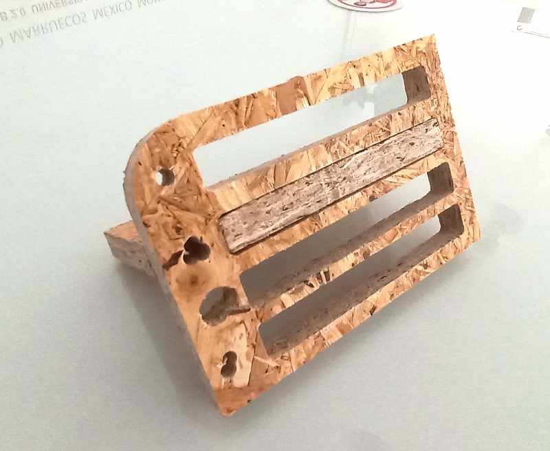
Test Joints Tolerance
First I send a test file with small joint test so I could decide what tolerance is the best for the fits before cutting all the pieces, and a specific layer with the offset tolerance according to de test.
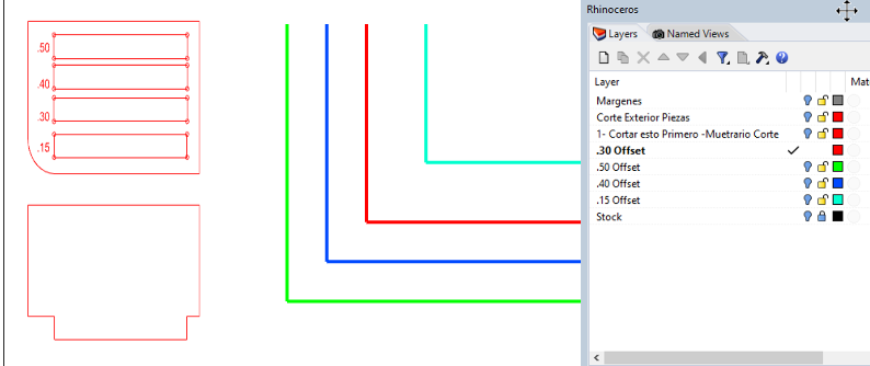
After exporting in Rhino the DWG file I import it to ENGRAVE??? for generating the GCode.
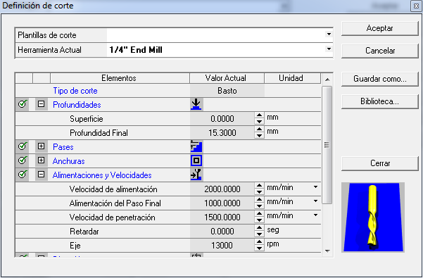
I have to choose the proper setting according to the data Sheet of the CNC Machine with the recommendations for OBS cutting.
Entry Speed is the first layer velocity, if it´s to high can hurt the superior layers of the material.
Cut Speed - 2000 RPM
Last Layer Speed - The speed of the last layer cut helps maintain the pieces in their place.
Type of cutting operations
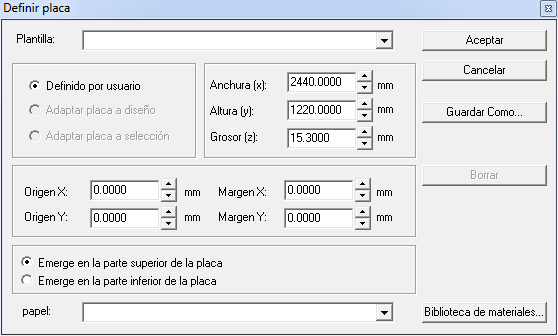
Assign the material stock dimensions and height.

I select the end mill size speeds and velocities.
At the beginning I use a 1/4" End Mill, with a 5000 mm/min Feed Speed, 3500 Penetration Speed and 1300 RPM. But the sound of the cut doesn´t sound nice, it start cranking, so I decided to slow down the Feed Speed.
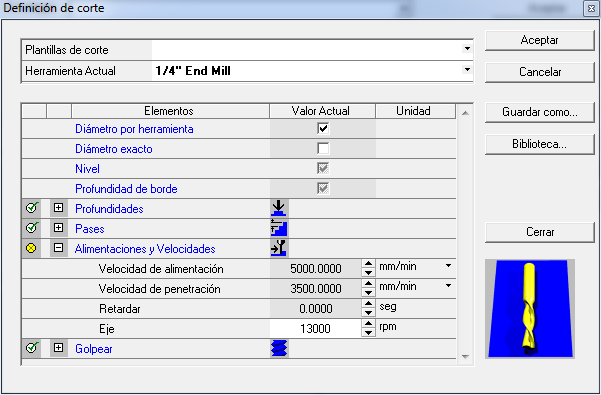
I change the Feed Speed to 2000 and worked very well.
After arranging the pieces in horizontal position I have to assign each type of cutting process depending on their shape or function.
The external cuts are called males were the spindle travels outside the cutting line.
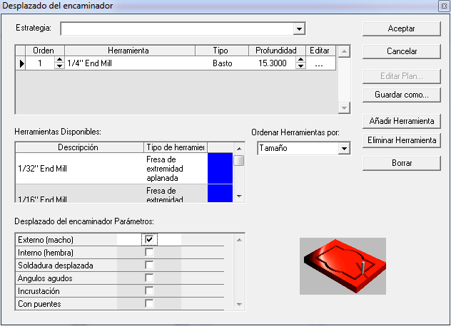
The internal cuts are called females were the spindle travels inside the cutting line.
I send the first test to 5000 Rpm but it was very hard and the cut began to generate big (astillas), sound very cranky and the superficial quality was´n good. I stop the test and change the speed to 3000 Rpm, after changing the speed the cut the cutting noise sound smoot and stable.
After I finish the assembly test, I check that a tolerance of 0.3 mm works fine to make the right fits into the joins.
I activate the layer according to 0.3 tolerance, arrange the shapes into the material sheet and send the cut trough Ethernet to the router.
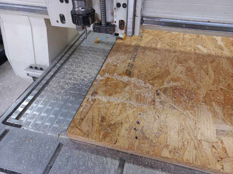
I activate the cutting from the CNC machine hang control.
From time to time u have to move the supporting clamps because the some of the cutting lines were just in the edge of the material.
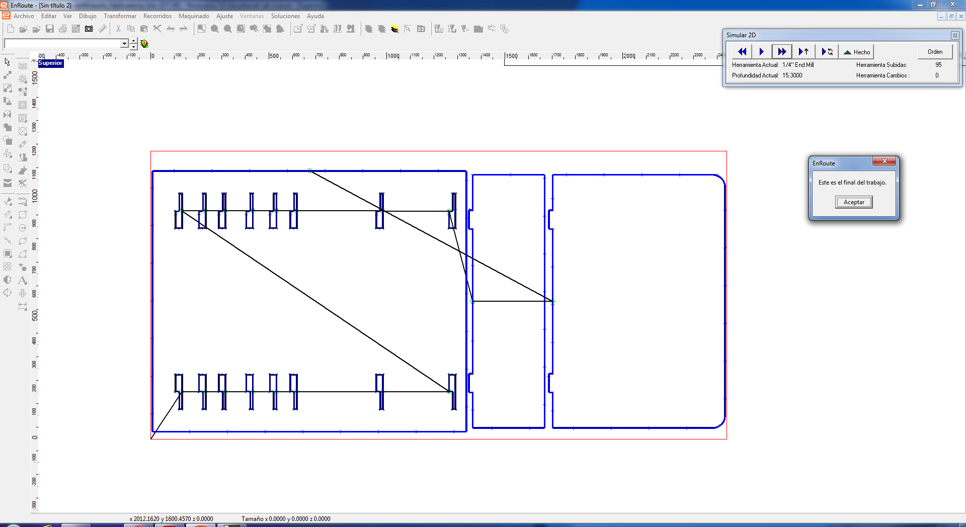
When all set, I simulate the toolpaths.
Fabrication
I stopped the cut and slowdown the Feed Speed from 5000 to 2000 RPM.
Test Joint from 1, 2, 3 and 4 mm, the best fit was 2 mm
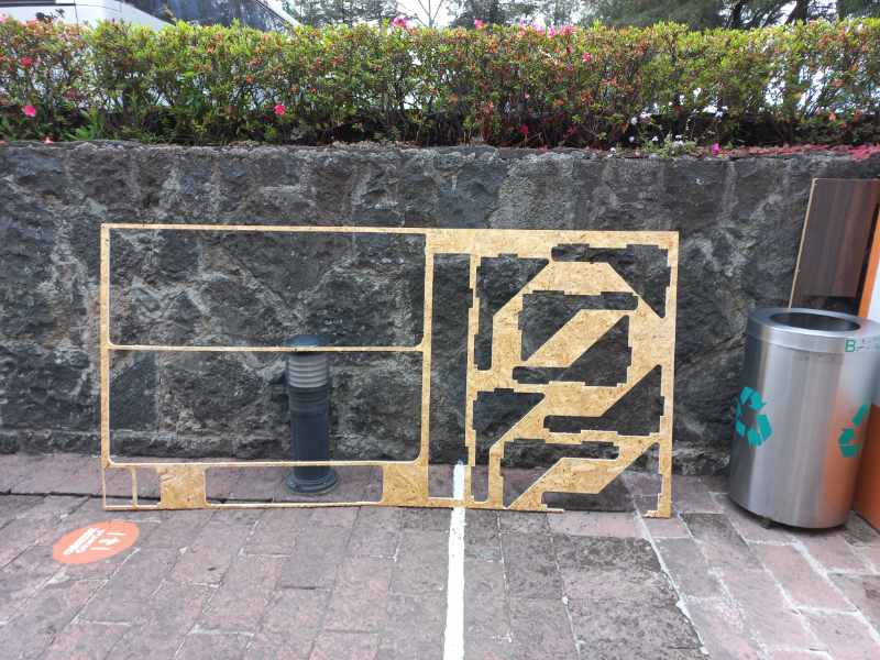
Leftovers
RhinoCam Tool Path Simulation
Checklist
- [ ] Linked to the group assignment page
- [ ] Documented how you designed your object (something big)
- [ ] Documented how you made your CAM-toolpath
- [ ] Documented how you made something BIG (setting up the machine, using fixings, testing joints, adjusting feeds and speeds, depth of cut etc.)
- [ ] Described problems and how you fixed them
- [ ] Included your design files and hero shot photos of final object