Intro:
The process for electronic production.
The process for electronic production.
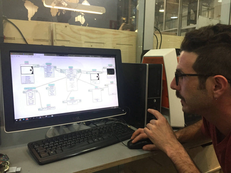
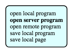
A little explanation about how to set the Mods platform.
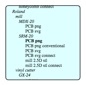
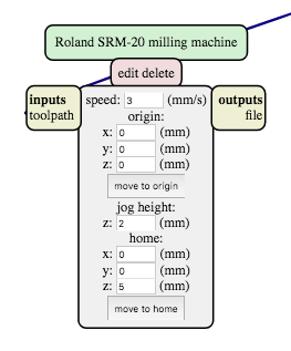
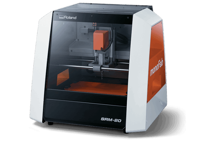
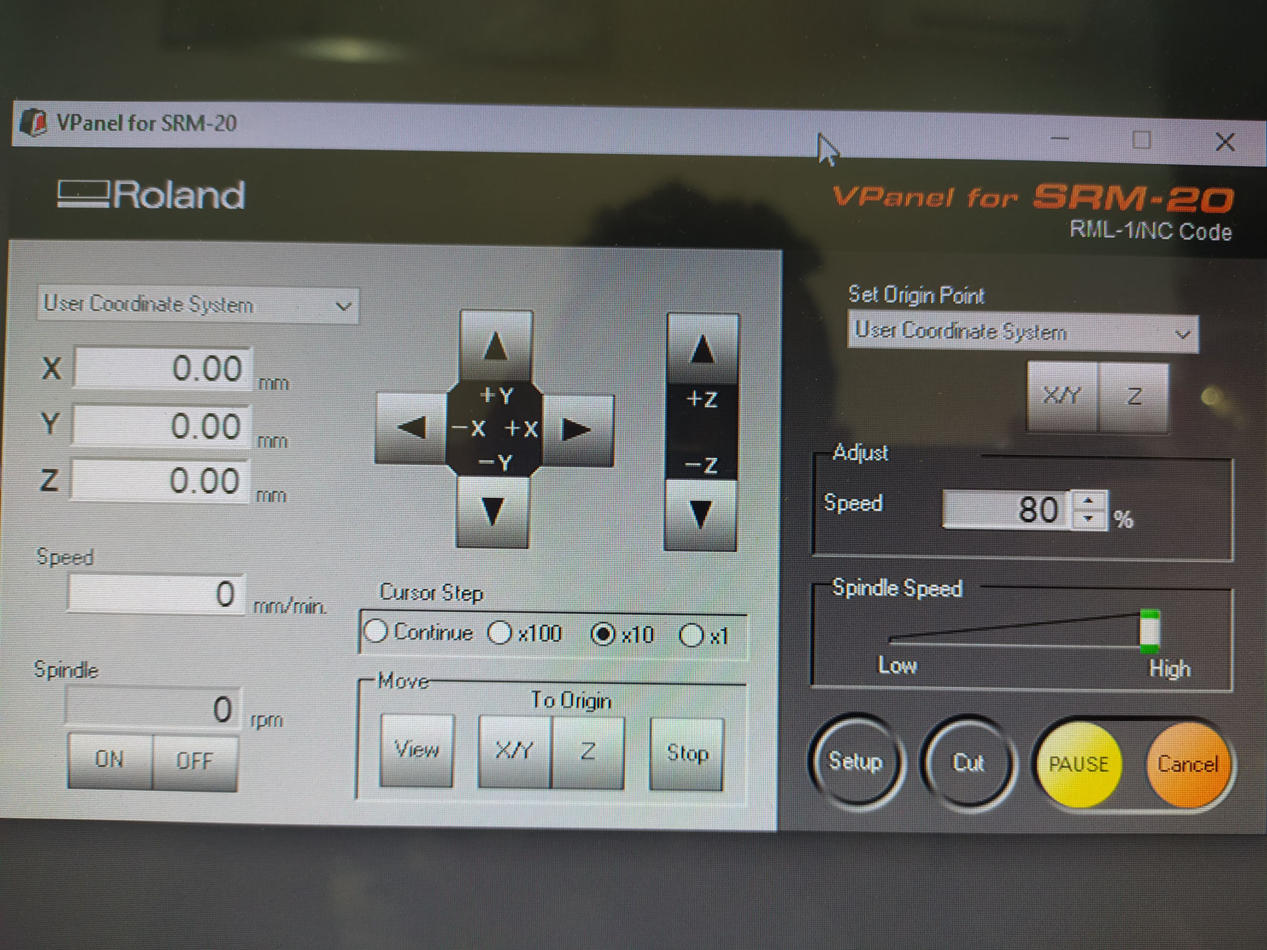
Instructions and tips for the use of the Roland SRM-20.
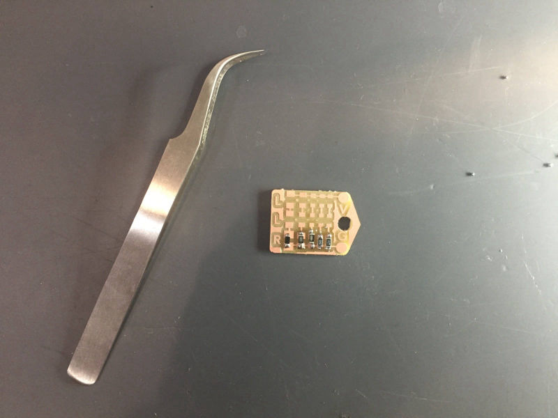
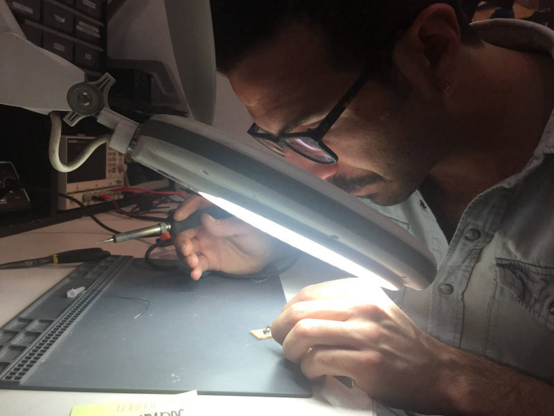
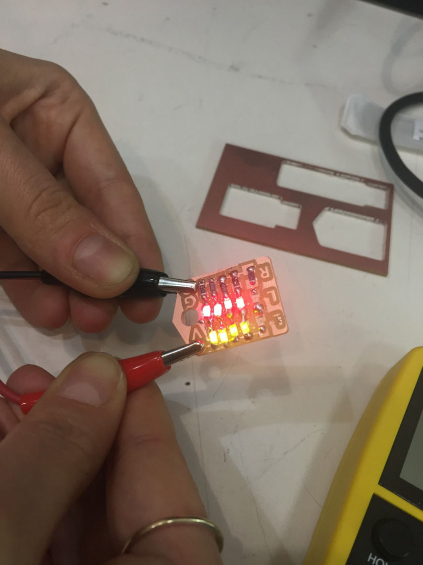
Soldering Exercise.
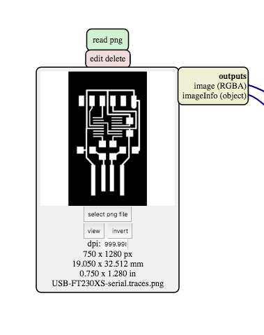
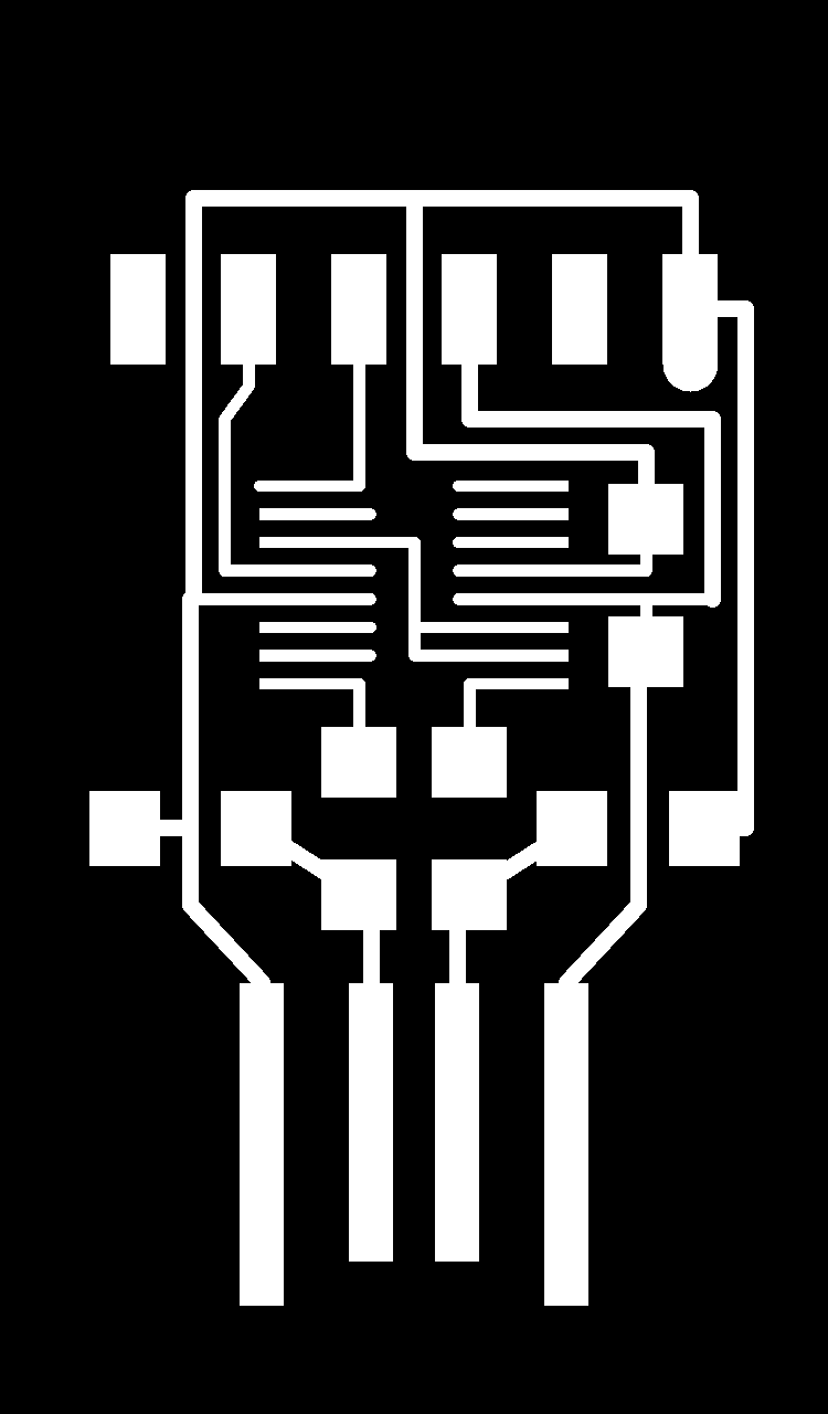
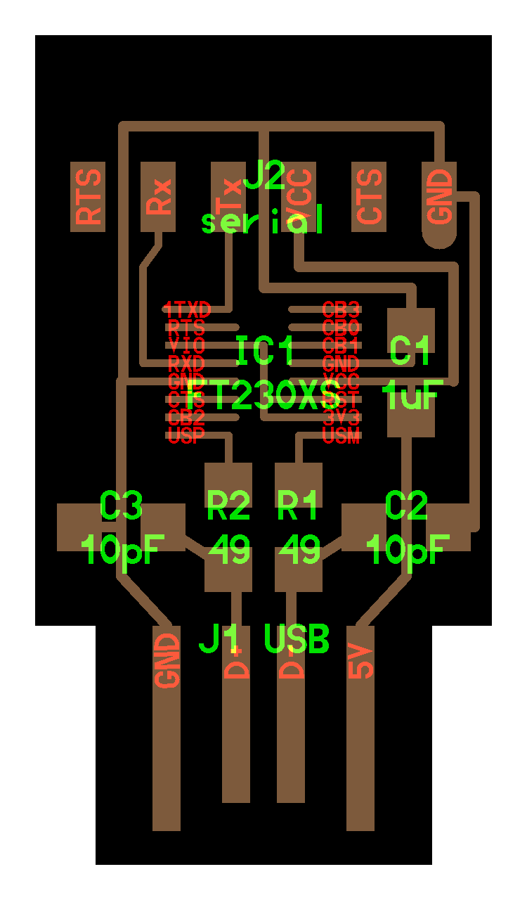
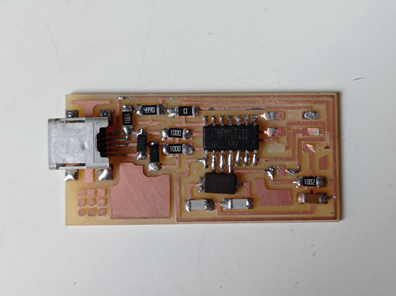
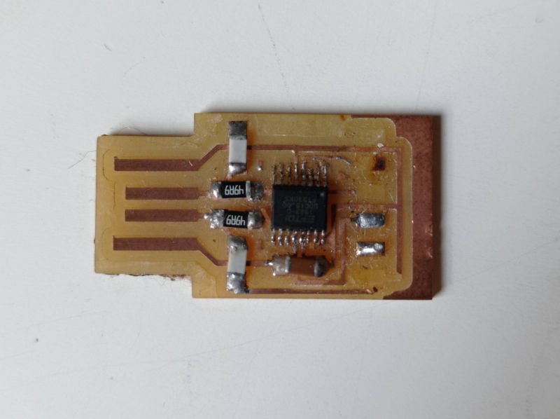
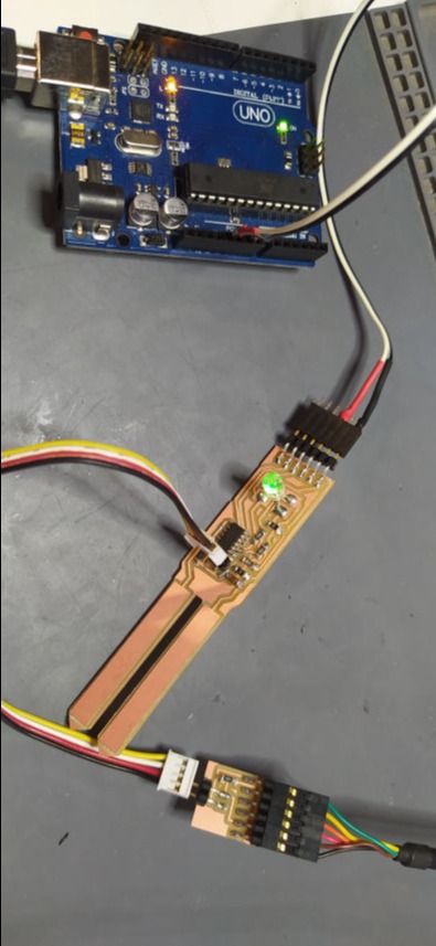
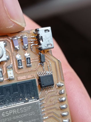
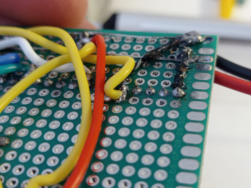
Usb to FTFI soldering.
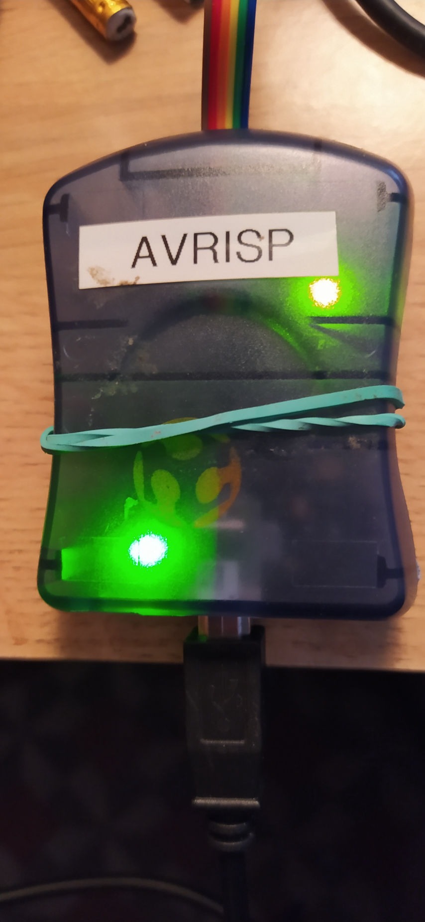
Some other programmers I built.
Some tips I learned for a better soldering.
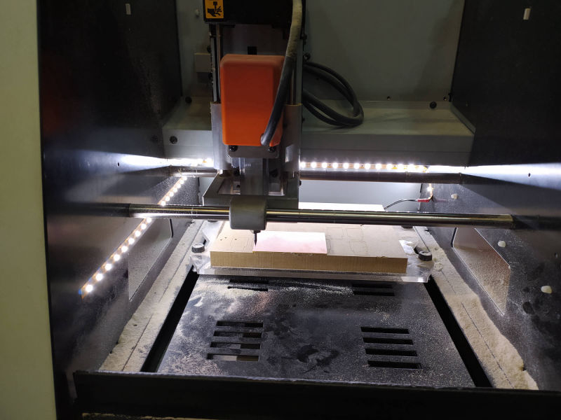
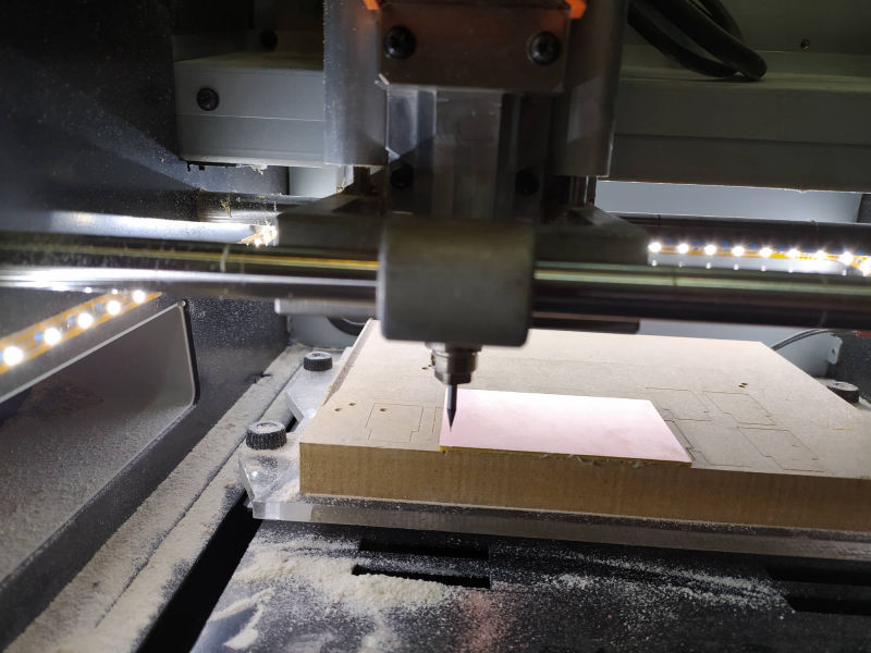
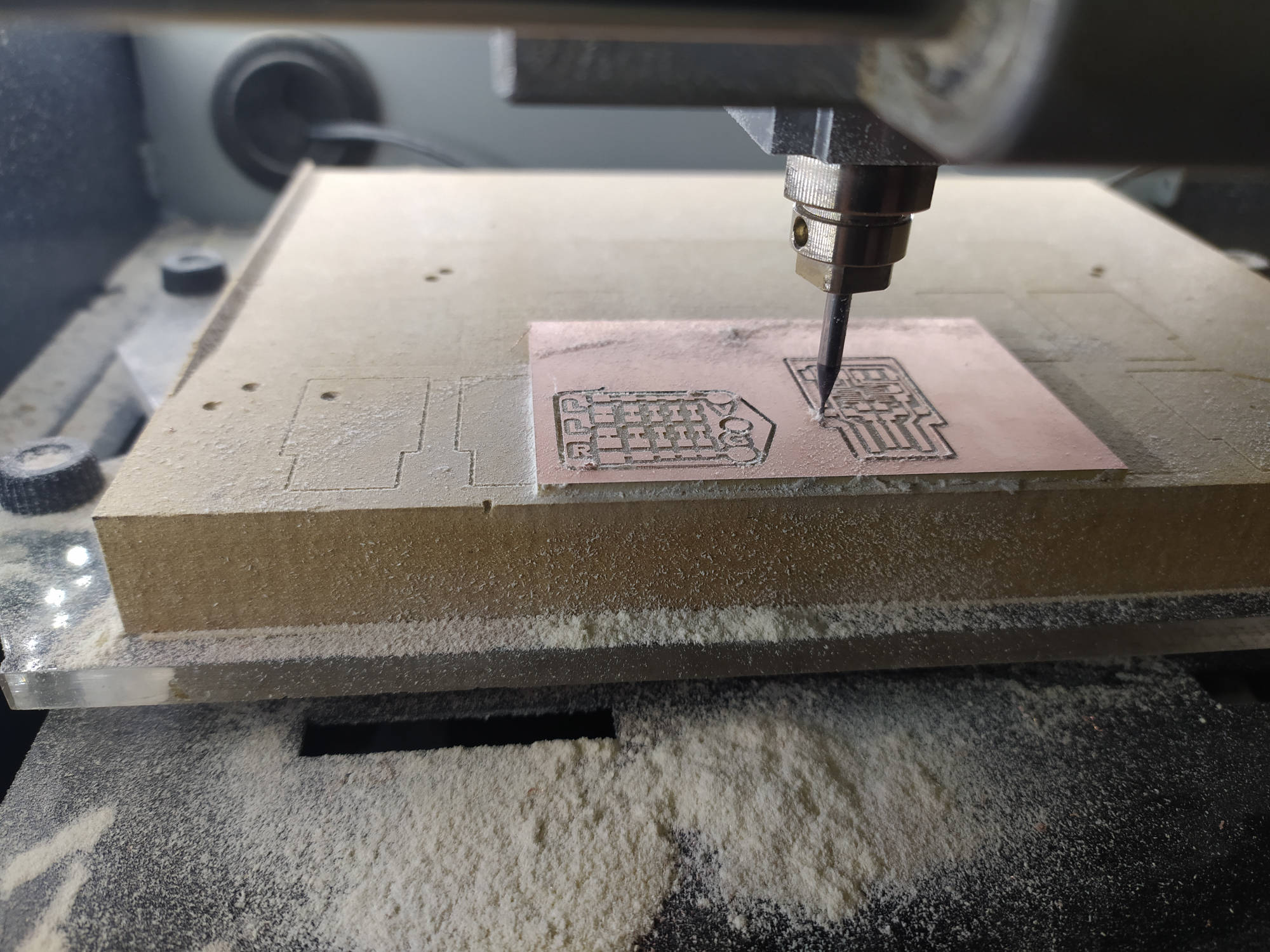
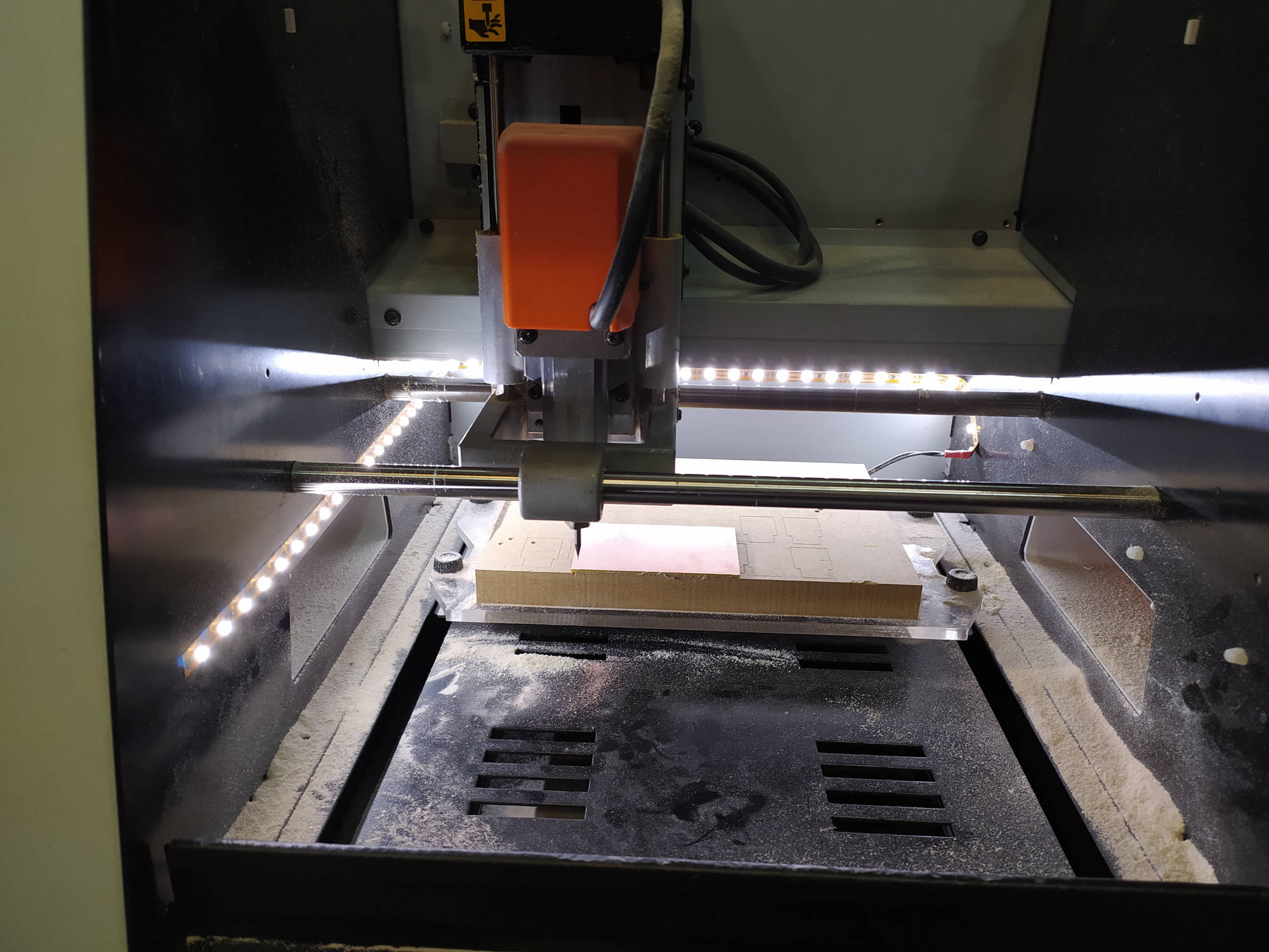
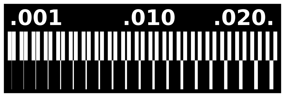
Testing the machine and end mill accuracy.
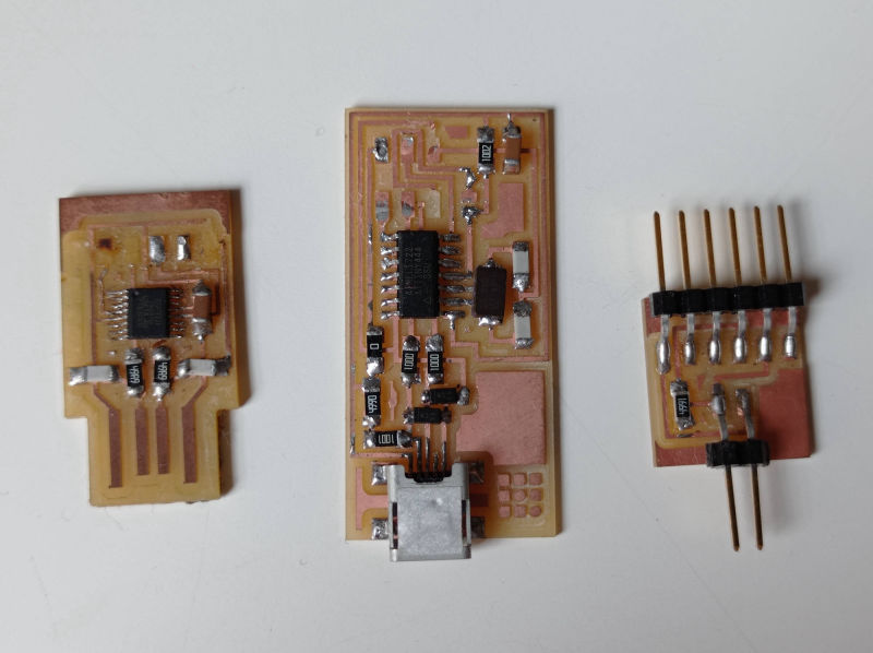
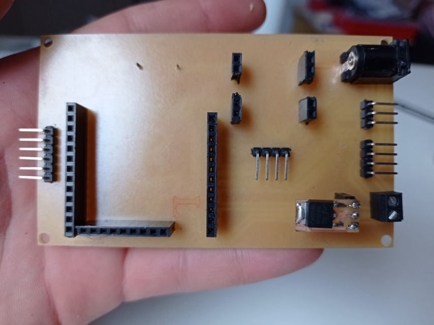
This week we were learning electronic production. Not so much about designing the circuits, but more about cutting them in the milling machine and soldering them. We created a LED BADGE as a soldering exercise and a USB to FTDI PCB board's.
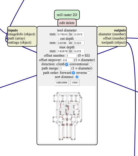
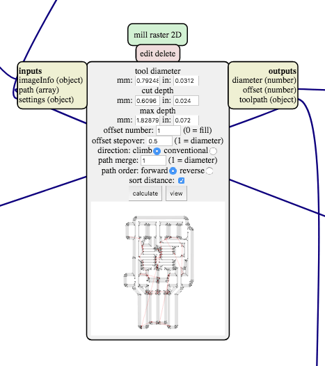
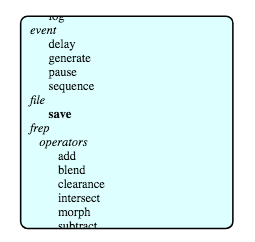
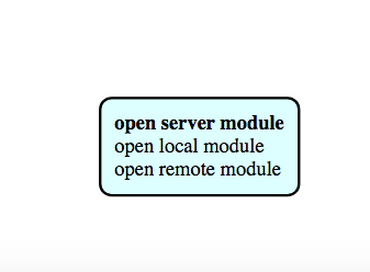
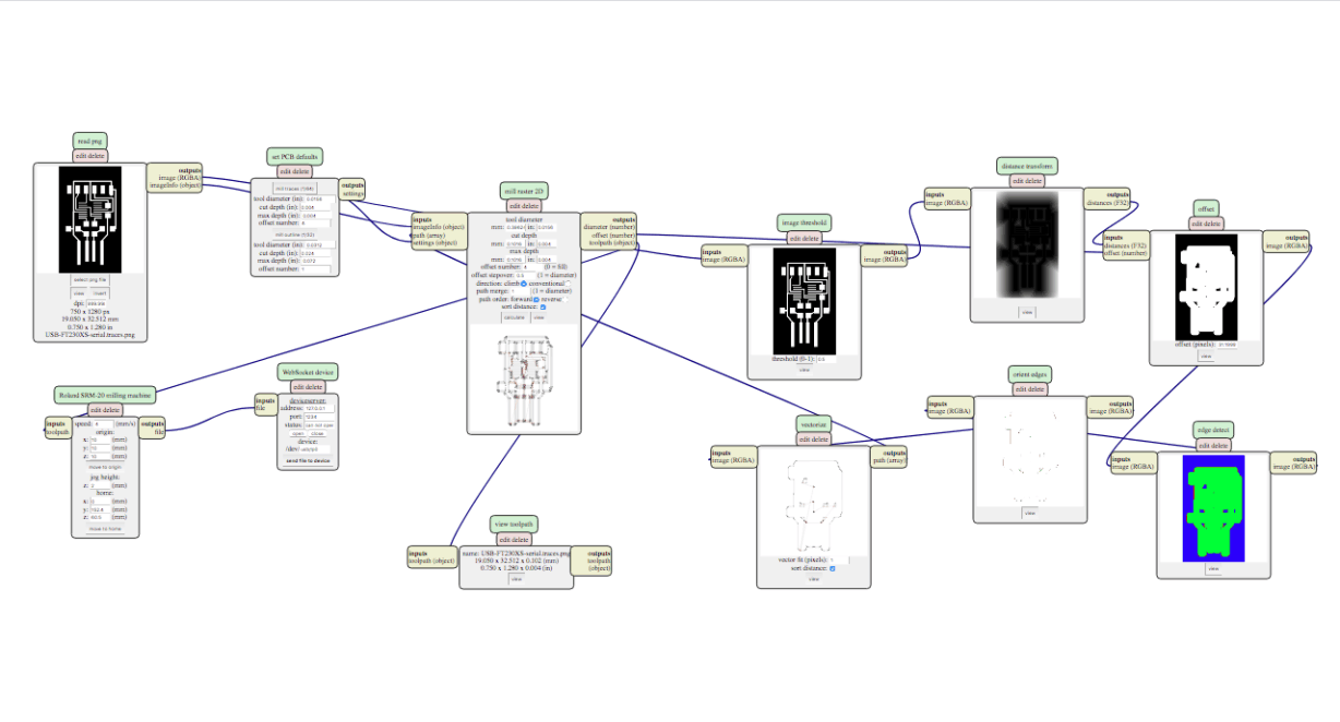
We Milled them in a SRM-20 milling machine, and for that, the first we had to do, was to prepare the files in the MIT MODS platform or Fabmodules.
I must say that I soldered the FTDI module and my partner soldered the LED BADGE (hehehhe)
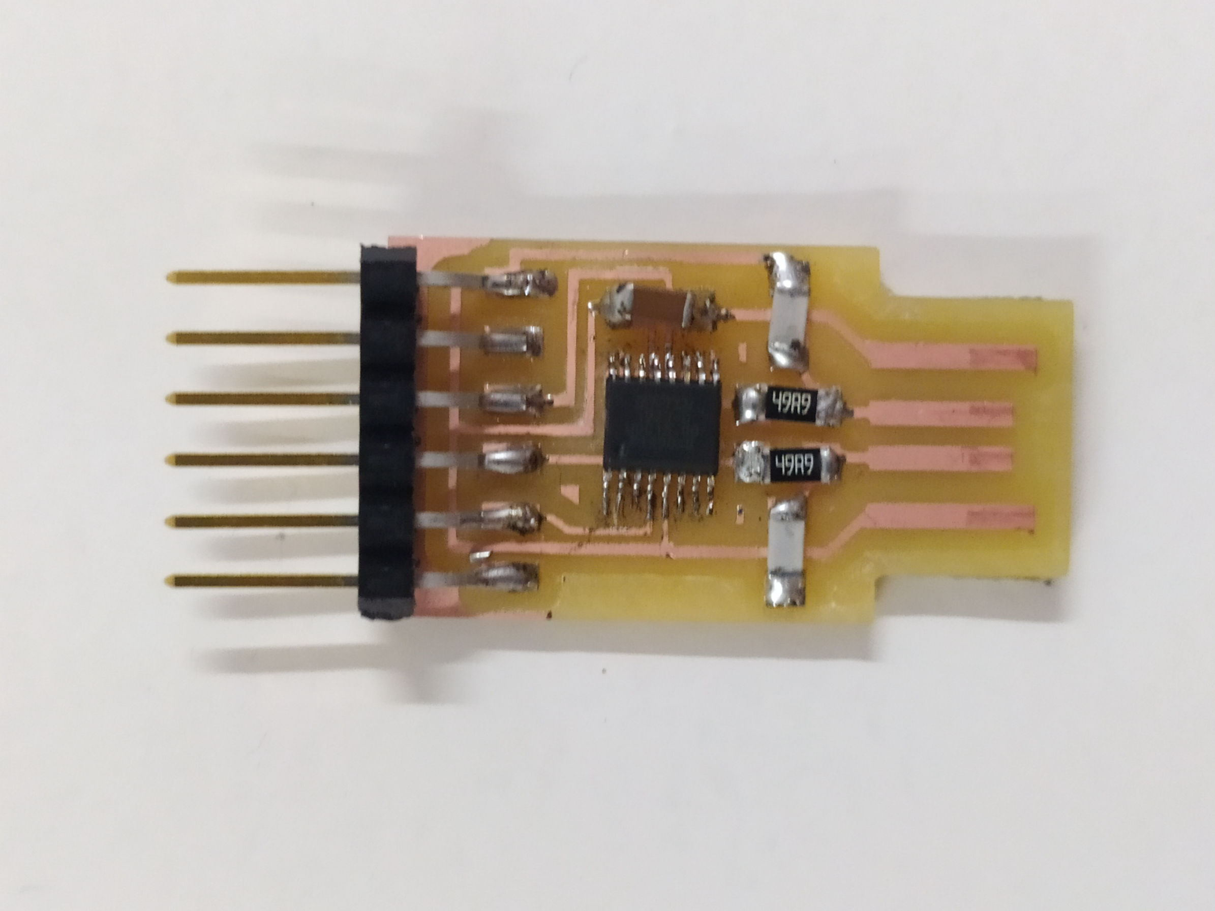
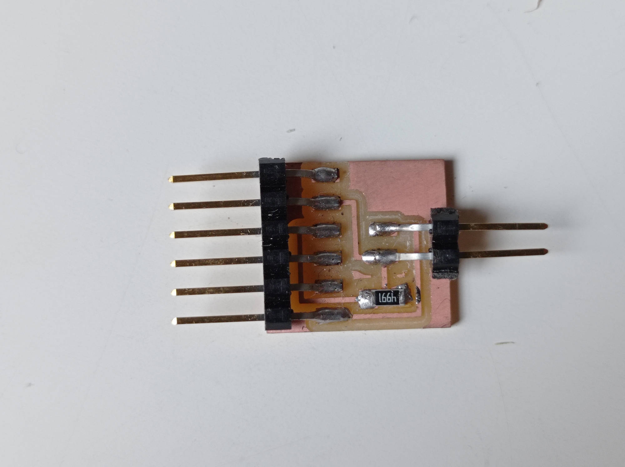
USB to FTDI
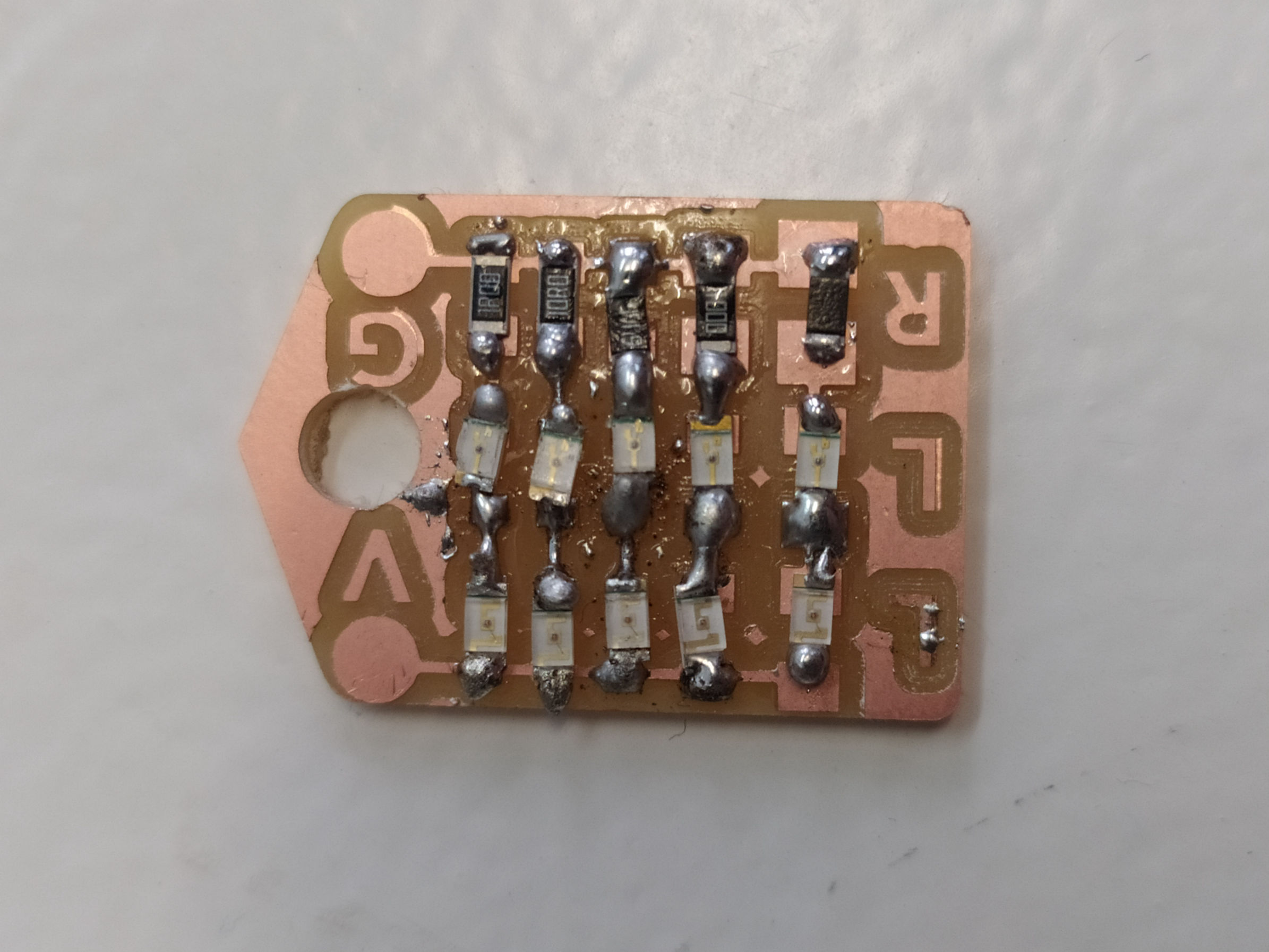
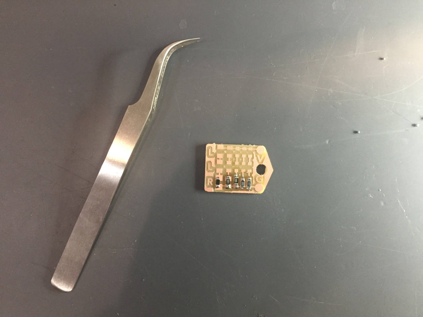
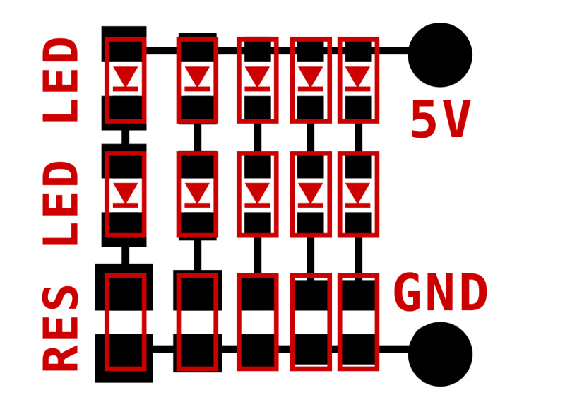
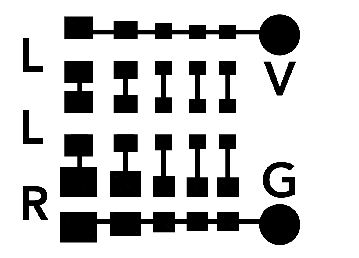
LED BADGE
We use this board as an initial soldering practice, before switching to the USB to FTDI, which has more complicated components such as the microcontroller.
For this we had to use 10 LEDS, and we decided to use 5 red and 5 green to have variety. We also decided to use different types of resistors such as 200 OHMs, 100 OHMs, 49.9 OHMs, 10 OHMs and 1 OHMs, to see the difference generated by them.
SOURCE: Learn Adafruit
There are two ways to program an AVR microcontroller. One is to reprogram the entire chip using an AVR programmer. The other is to use a bootloader that is pre-programmed onto the chip that allows the chip to re-program itself. An AVR programmer is more powerful: you can really mess with anything on the chip and the entire 32K of memory is available. Using the bootloader is safer: there's no way to mess with the fuse settings (which could brick the chip) but you only get 30K of memory since 2K is used by the bootloader. Not a big deal, but if you are working on a big project which requires tons of flash space, you may need it.
AVR programmers are more powerful in that you can program any AVR, even blank ones from the factory. But that also means you have a pretty good chance of 'bricking' the chip!
FTDI adapters can send any serial data back and forth including updating AVRs with a bootloader on them. But you need to get that bootloader on there first, which basically requires an AVR programmer.
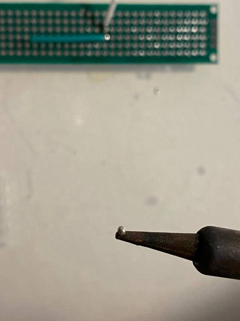
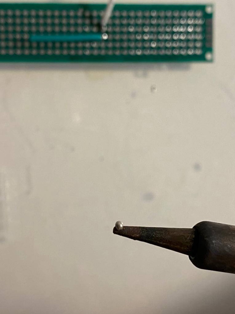
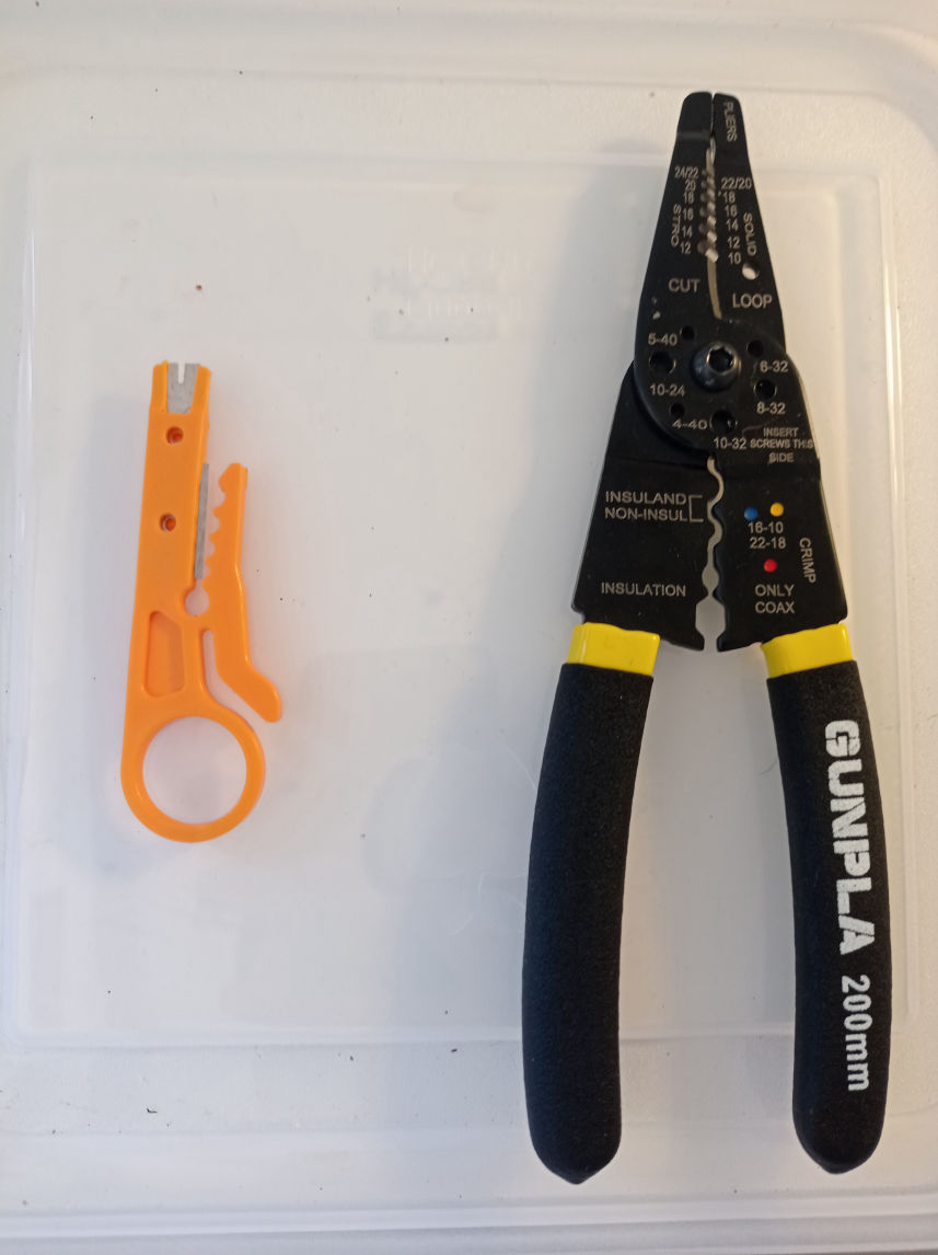
Solder from smaller to bigger!
It is always better to start soldering the smaller, more complicated parts, and the go with the bigger, easier, faster parts.
So for example, if you have an FTDI or MicroUSB, you should better start with those, test them with a multimeter to see if they are not in short and that they are properly connected, and then continue with the rest.
Another good tip in this small parts is to first solder one leg and check that everything is in position, before soldering the rest. It is better if you also clean your tip for each leg you solder.
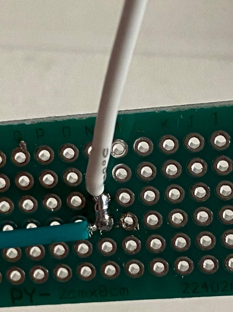
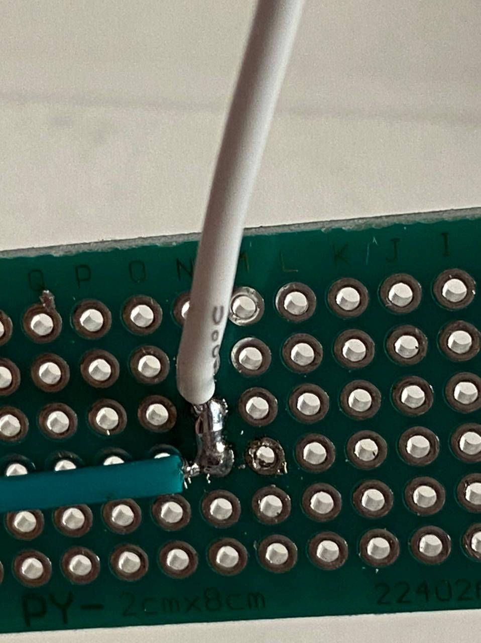
Another good tip, as long as you can choose, is to use trougholes instead of SMD pins (my preference), because they will grab harder from the PCB and last longer. But a better tip than that, is to solder your pins backwards whenever you can. For that sometimes you might even need to design it all backwards, but it worths it a lot, since that is going to help you a lot to solder your pins properly to the copper part, because if not, you will have to manage to get the soldering tip under the plastic female pinholes and you will probably burn them and also because they hold much harder.
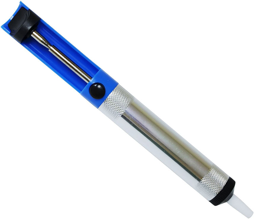
Soldering Sucker
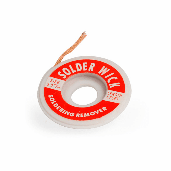
Soldering Wick
(Desoldering Wire)
Some other problems you might have are:
EXCESS SOLDERING:
Which can be easily removed with a Solder Sucker or a Solder Wick. The soldering Sucker will help you remove overall excess by sucking the soldering when you charge it and press the button. While the soldering Wick needs you to add some soldering first over the wick, then put it over the part you want to desolder or clean, and press it with the tip of the iron so that it absorbes the excess of soldering.
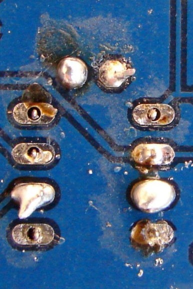
COLD SOLDERING:
Your solder should end up shinny, because if not it might not have melted correctly and it will not grab so strong. This can also be caused by using a bad quality soldering, which melts pretty bad.
(Image Source ADAFRUIT)
COLD SOLDERING
SHINNY SOLDERING
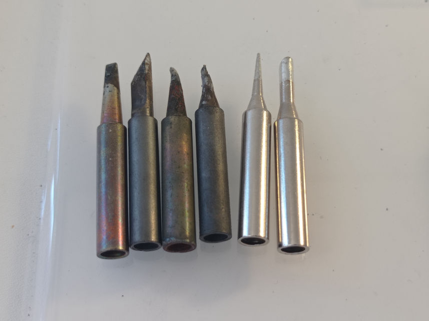
Aluminium Tips
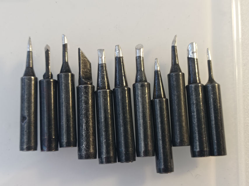
Iron tips
Cheap vs Good
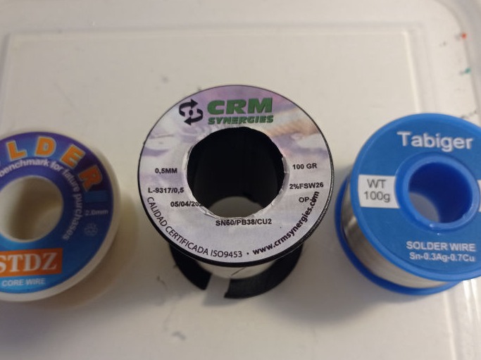
Chino's / The Love of my life soldering wire / Amazon
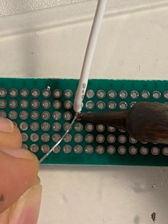
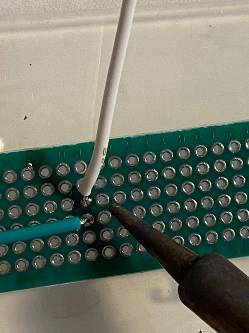
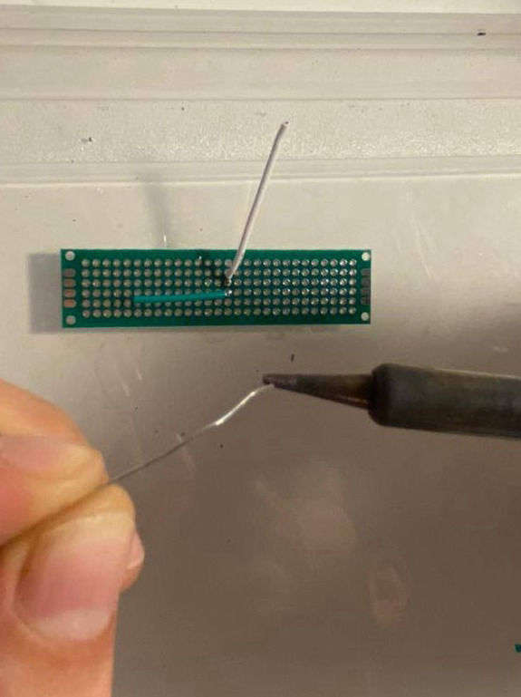
To solder, what I do is to touch the metallic/copper contact part of the board while touching also a little bit of the wire, so that they both heat up, and then, in the other side, I touch it with the soldering wire and it easily melts.
I have been trying with different temperatures for soldering, and I think that for my soldering iron and soldering wire, between 350º and 400º is pretty good.
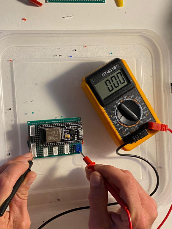
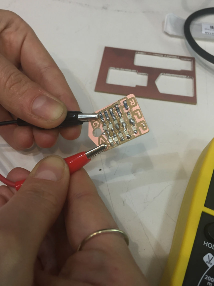
Test as you solder:
It is better to test every connection after making it, before continuing to the next one, because with that you will find the problems early and debug them faster than testing all connections after you have already soldered everything... and sometimes, when you soldered everything, it makes it more difficult to desolder small components or the ones that are very close to each other.

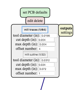
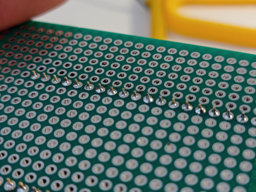
I had to do 3 different tests because the bed was not properly calibrated or the PCB was not sticked well to the bed, so in the first pass, the machine left a lot of material. I also made a mistake the first time I created the file in mods because I let the offset in 4, what gives only one pass around the traces an leaves a lot of material.

In the second test, I forced the Z axis home to be 0.10mm lower than the real home, and changed the offset of the file to -1 (for it to clean a lot more material). But the problem this time was that I forced the Z way to much, so this time it removed a lot of material from the PCB. Usually when I force the Z axis, I lower the machine Speed to 80%, I run the spindle and start lowering in small amounts until I see it starts peeling some cooper and white PCB material. Then I set it, and after that I lift it about 100 steps and then turn off the spindle (not before lifting it).

So for my third try, I did it by forcing the Z home only 0.03mm and with -1 offset, so this time it removed it correctly, but anyway it did not do a smooth trace, probably because of my end mill or the amount of force, so it looks a bit rusty.

Made with Mobirise theme