Fab Academy 3

Computer-Controlled Cutting

INDEX:

Here you will find an Index with links to easily navigate through the section content.

1

Laser Cutting:

What is Laser Cutting and how it works.

2

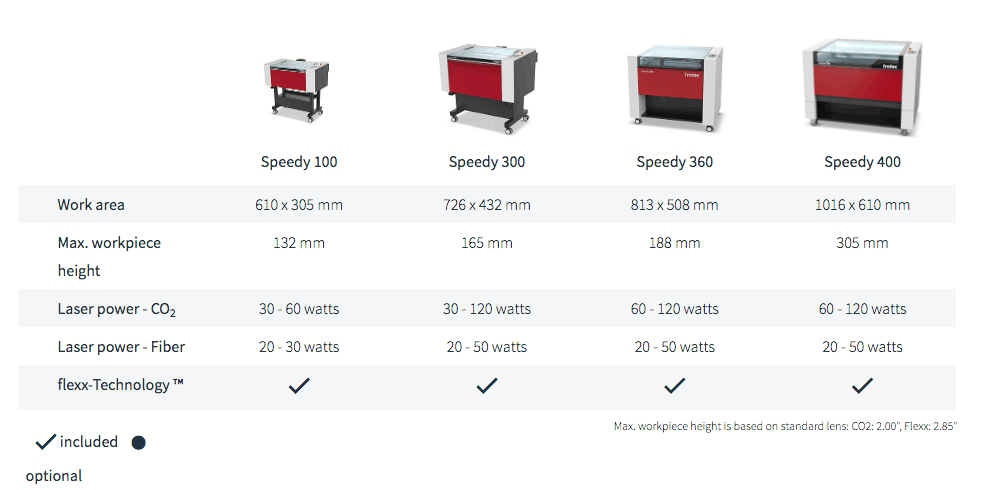
Types of laser cutting machines:

Different types of Laser Cutting Machines and some of their specifications.

- CO2
- Neodymium (Nd-YAG):
- Fiber

4

Laser Calibration and Testing:

Here is the explanation of how to calibrate the laser cutter and some test I did.

- Laser Testing.
- Flexible Kerf Testing.

5

Parametric toys design:

A brief description of the parametric design process.

7

Reflections and Considerations:

Final reflections and considerations about this week.

1 - Laser Cutting:

What is Laser Cutting and how it works.

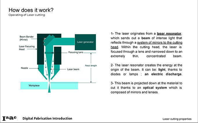
Laser cutting is a technology that uses a high-power laser, that is directed through mirrors to end up in an optic lens that focuses it and generates a laser beam to cut materials. It moves in Y and X axis, and has also the possibility to move the bed Z axis to help you focus it on the material. It is Computer Numerical Controlled through a G-Code of the pattern to be cut, melt, vaporize away, raster or engraved onto the material, leaving an edge with a high-quality surface finish. Industrial laser cutters are used to cut flat-sheet material as well as structural and piping materials. I could say that laser cutting machines works similar to when you play with the sun and a magnifying lens to burn a piece of paper... in a simplified way.
Mobirise

2 - Types of laser cutting machines:

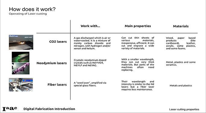
Laser cutting machines can be divided into three, based on the type of laser they use.  FabLab BCN Wiki

CO2 Laser cutter machines:

Process: A gas discharged which is air or water-cooled. It is a mixture of mainly carbon dioxide and nitrogen, with hydrogen and/or xenon and helium. The CO2 laser transmission medium is air, which travels in a straight line and changes its transmission direction by a mirror. It is susceptible to the external environment and may require the maintenance of these mirrors, thus slightly increasing the cost of use.

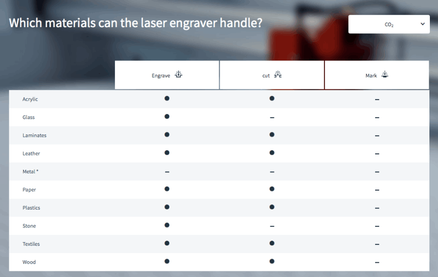
Main properties: Can cut thin sheets of various materials, inexpensive, efficient. It can cut and engrave a wide variety of materials.

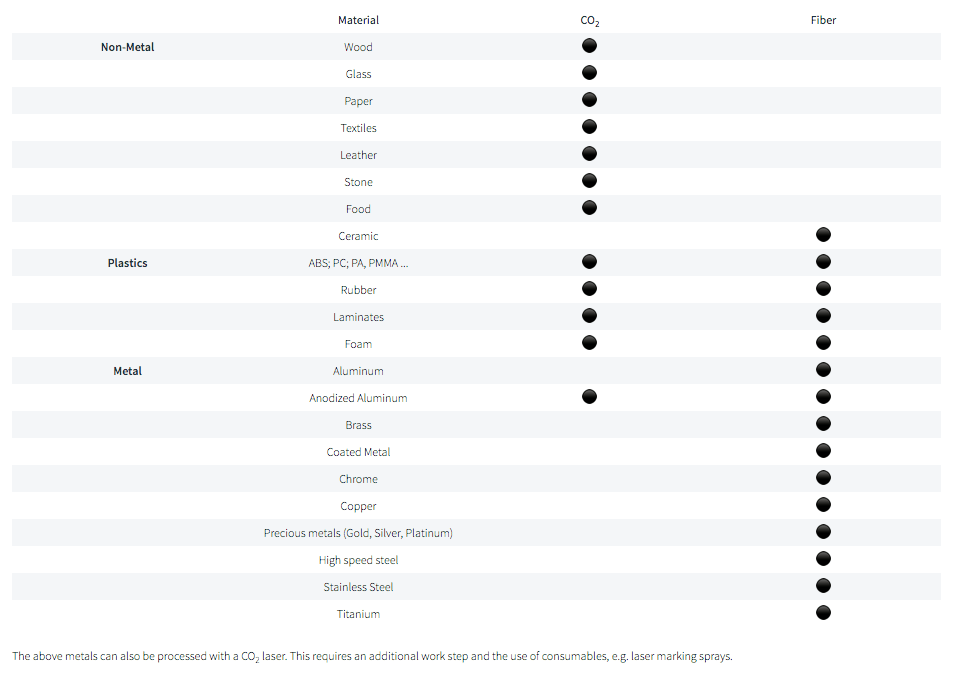
Materials: Wood, paper-based products (like cardboard), leather, acrylic, some plastics, and some foams.

Neodymium laser cutter machines (Nd-YAG):

Process: YAG laser definition: Neodymium-doped Yttrium Aluminum Garnet (Nd-YAG) laser is a solid-state laser in which Nd: YAG is used as a laser medium. These lasers operate in both pulsed and continuous mode. Nd: YAG laser generates laser light commonly in the near-infrared region of the spectrum at 1064 nanometers (nm).

Main properties: With a smaller wavelength, they can cut very thick materials. But parts of the machines often need replacing.

Materials: Metal, plastics and some ceramics.

Fiber Laser cutter machines:

Process: A “seed laser”, amplified via special glass fibers. The transmission medium of the fiber laser is an optical fiber, and the light beam is enclosed in the optical fiber and “curve propagation” is not affected by the external environment.

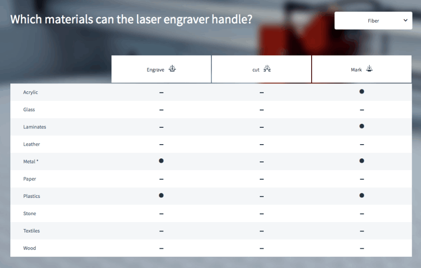
Main properties: Their wavelength and intensity are similar to the Nd-YAG lasers but a fiber laser requires less maintenance.

Materials: Metals and plastics.
Mobirise
Mobirise
Mobirise

Co2

Fiber

3 - How to Laser-Cut:

Here is a tutorial I created to Laser-Cut in the Trotec 500/1000:

Machine and Lab setting:


  1. Check that the ventilation is On before turning on the machine. The burning of materials like acrylic could generate some toxic gases, and also contaminates the mirror so it wont work as expected.
  2. Turn on the machine with the lid closed and wait for the bed (Z axis) to go down until it stops in the bottom. Then raise the bed again until it´s about 200 mm from the tip of the nozzle.
  3. Add the material and check that it is not lifting in the corners. If it is bending up, maybe you could solve it by turning it around. Remember that the upper side, is going to be the side that will be raster. You can also add some paper tape to prevent it from lifting.
  4. Calibrate the machine with the tool, by hanging it from the nozzle and manually moving the Z axis up slowly until the calibration tool falls, right after slightly touching the material. In that exact point, you will have your machine calibrated.

Setting File in Rhino:


  1. You can create previously the file in Illustrator or Inkspace, and export it as a DXF. Then open it in Rhino, in the computer connected to the machine.
  2. Generate a rectangle the size of the machine to check if your file fits on the cutting space, check that the file you want to cut fits in the rectangle, and erase the rectangle:
    - 1000 x 600 mm / Trotec 400.
    - 600 x 400 mm / Trotec 100.

            ***if you don't erase the rectangle, the Trotec software is going to recognize it             as an enormous image and it is going to give you wrong time estimations.
  3. Check that you have separated the layers in colors, depending of the actions you are going to do, and the order in which you want them to happen:
    - Raster, inner cuts, outer cuts... (Black, Red, Blue, Green...

           ***If you are having trouble changing the colors of the materials you are going to              need to first Explode, Join and Make 2D the material before modifying it.
  4. Send the file to print (CTRL+P) and the Rhino printing setup window will pop-up.
  5. MAKE SURE THAT:
    - Aspect ratio is 1-1
    - When you press Setup, the file is in the corner of the canvas. If not type "MOVE" and select te corner of the canvas and the corner of your file. If you don't type MOVE first, then you will resize the file and that is not what you want.
  6. Press Print. The file will open in the Trotec Job Control, the software that this Trotec laser uses for "pre-cutting".

Trotec Job Control

  1. Click in the button in the lower right corner to connect the software to the machine.
  2. In the Laser machine, move the laser with the jog to the place on the material where you want to start cutting. A crossbow will appear on the software screen, according to where the laser is located.
  3. Drag your file and align it with the laser.
  4. Open The Material Database Window (Ctrl + M).
  5. Select the material you are about to use in the options.
  6. Define the processes for each color of the line traces on the file. (skip, cut, raster)
  7. Define the Power, Speed, and PPI/Hz. Depending on the material you are using and the process wanted in each color. Ask this in your lab and do previews tests to define the intensity you want.
  8. EXAMPLE:    4mm Plywood:           
                             CUT:  P 75 - S 0.5 - Hz1000
  9. Check that the machine is focused,
    with the lid closed,
    the vent is on,
    the material is in the right place and ready to cut.
  10. Check in the software the time, to see if there are no missing parts or strange times. Check the material cutting/rastering settings.
  11. Click play button to send the file to the cut.

4- Laser Calibration:

Mobirise

LASER CALIBRATION:

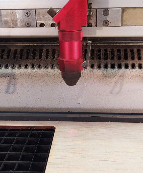
To calibrate the focus of the laser, you need to use a tool that usually comes with the laser (or could be fabricated in acrylic like the one in FabLab Barcelona).

You hang the tool from one side of the laser as it is shown in the picture, and then you start to slowly raise the bed until it softly touches the tool and makes it fall. That will guarantee that your laser is focused.

Other focus problems might come from a dirty lens, and in that case there are special cloths for cleaning it carefully.
5 - Laser Testing:

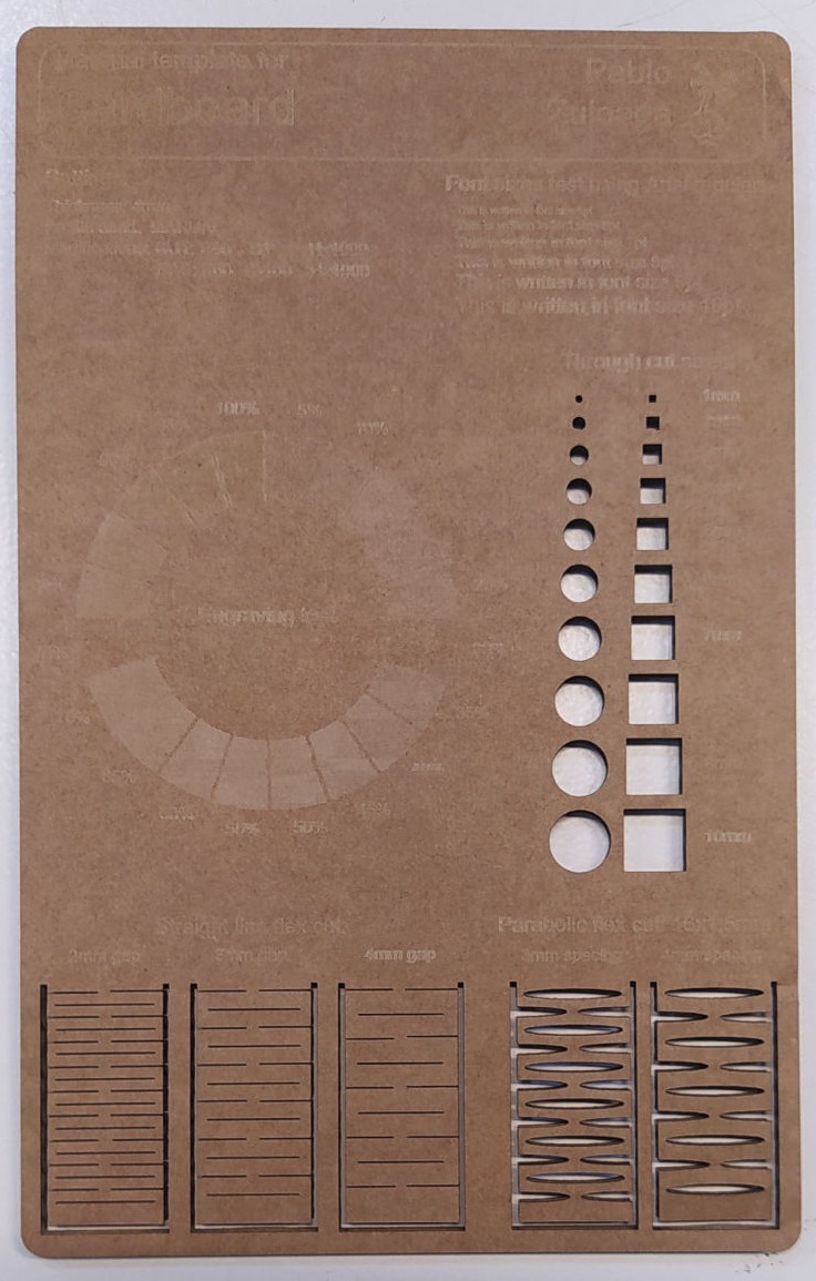
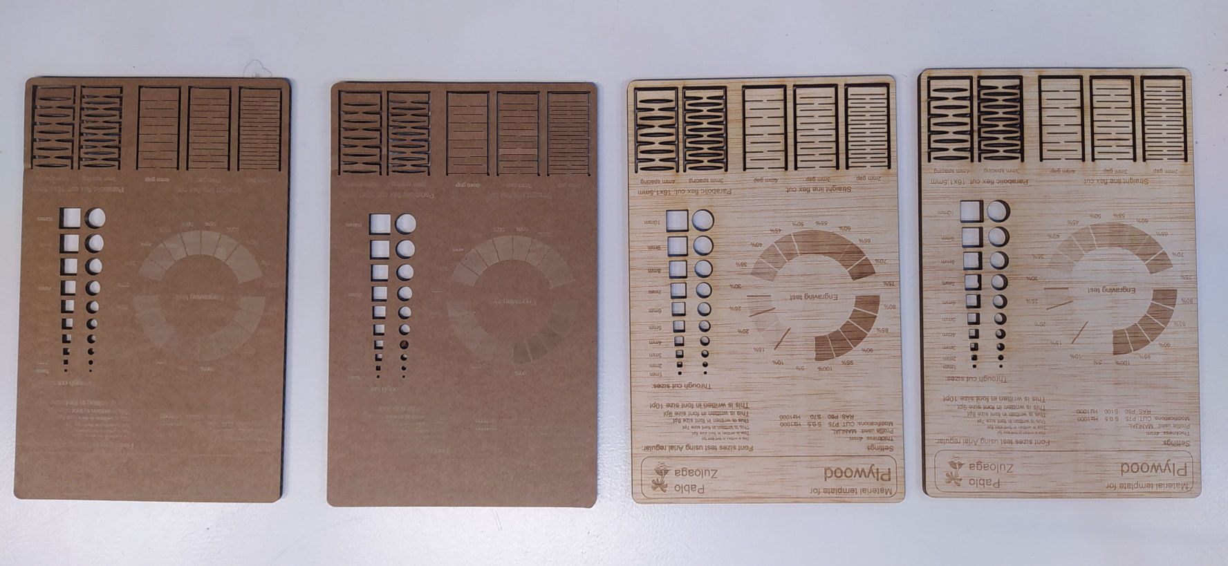
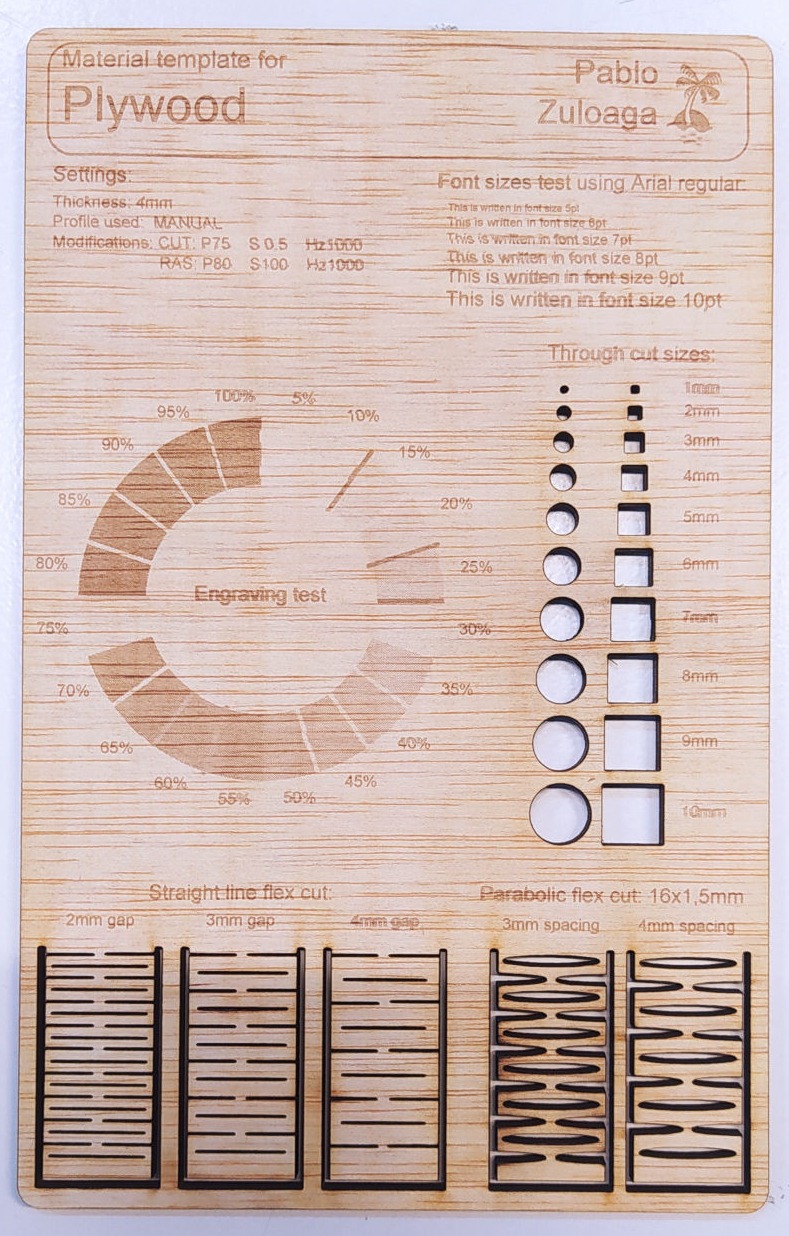
To learn a bit more about how to configure and calibrate the laser, I downloaded this "Laser cutting materiale template by Noloxs" from Thingiverse and adjusted it to create my version with different settings to test with cardboard and plywood.

This works pretty well to have different configurations tests in a lab, so everyone can check them and configure the machine according to the desired finishing they want on an specific material. On each card you can adjust the Power, the Speed and the Hz, and play with them to get different results. So if you have a high power and a slow speed material will probably cut or burn, but if you have a fast speed with high power, or a slow speed with small power, material will probably raster or not burn completely.

Understanding this, will give you a lot of variable options to work with different materials. In the end, the result depends of this three variables plus the type material, the thickness of it and how focused and/or clean the lens is.

After I did this test, I found this webpage with a lot of testing options that also seem to be pretty useful. I have not tried them, but will let the link in here to test them in the future.


Mobirise

6 - Kerf testing:

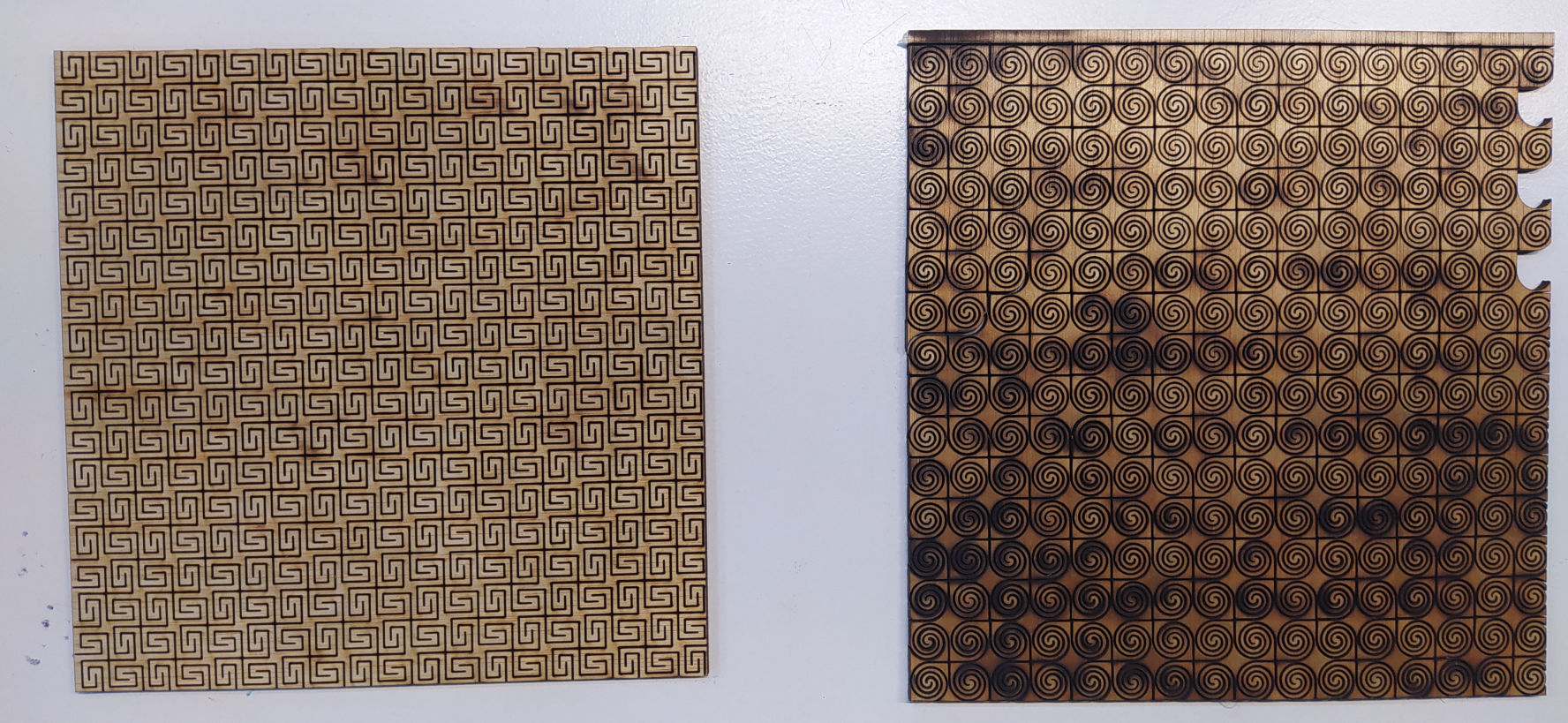
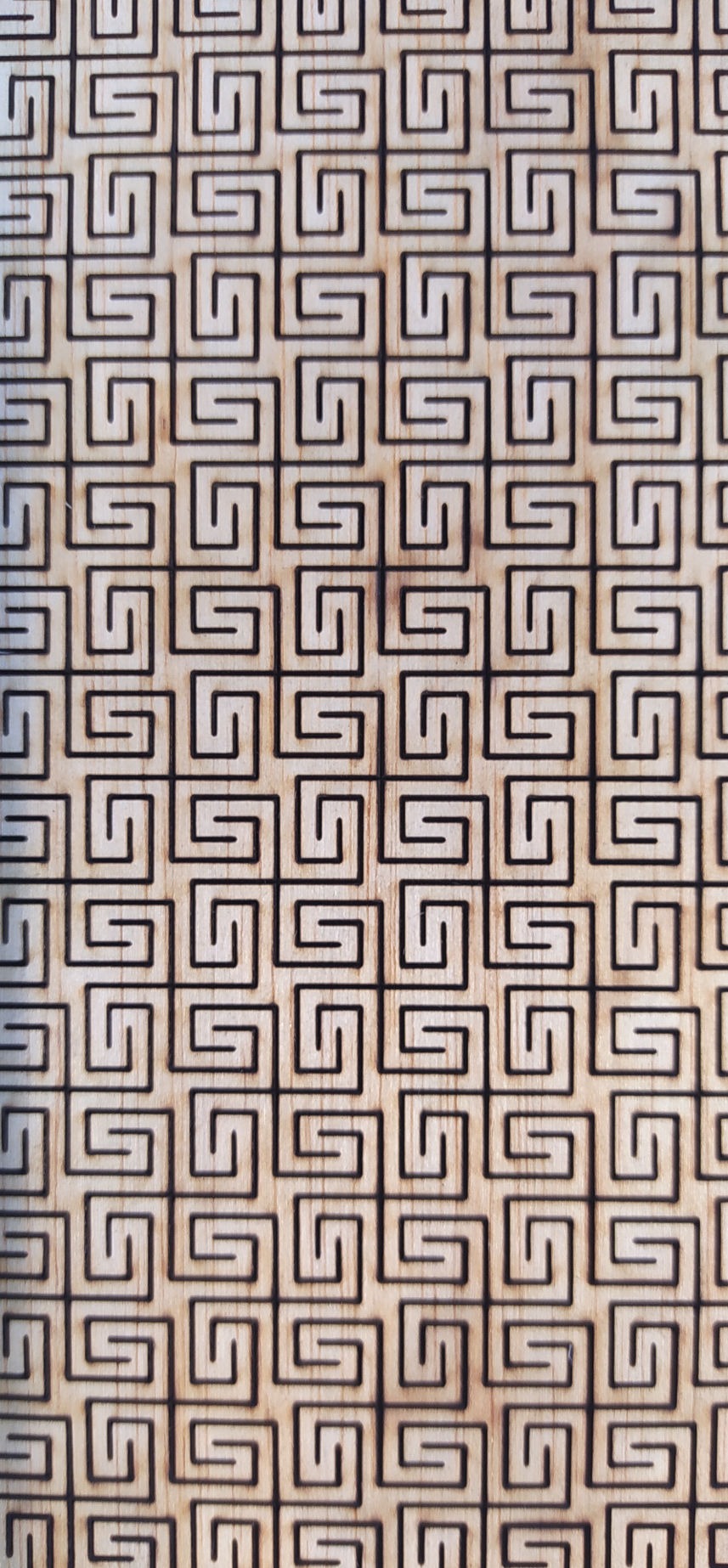
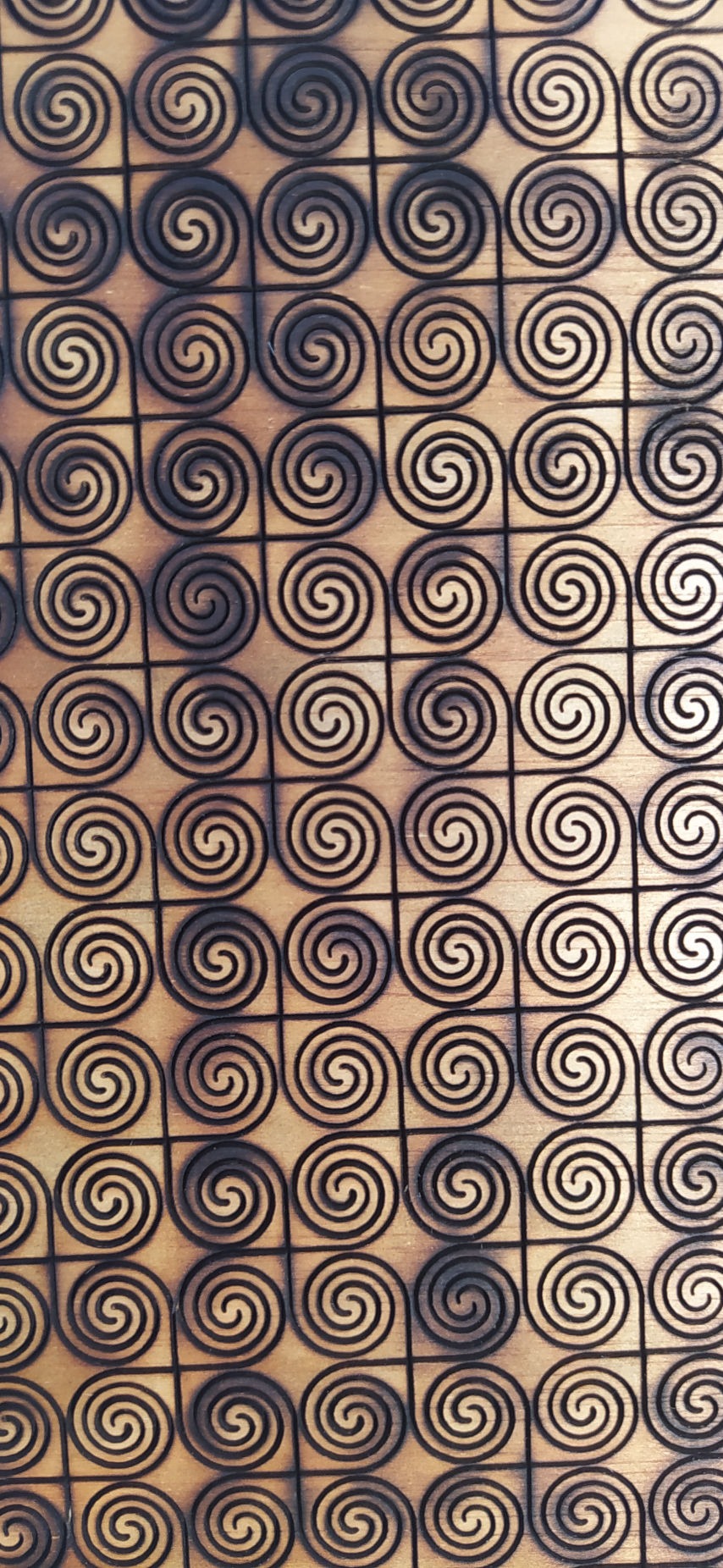
I also downloaded this kerf test from thingiverse to experiment a little bit with flexible cuts and it was pretty interesting how you can get wood to bend depending of the structure made out of the cuts.

The first model (in the left) was downloaded from http://lab.kofaktor.hr/en/portfolio/super-flexible-laser-cut-plywood/ and it actually work pretty well to make the wood flexible, it is just like magic and it also smells pretty good (I love the burn wood smell).

The second pattern (the one in the right), I haven't been able to find the source where I got the file (sorry), but the interesting thing about it was that the pattern was much bigger but I made the mistake of shrinking it so that it fits in a smaller size and that made that the lines where too close, and that generated a lot of material burning because the laser had to pass very close to a past burn.

While writing this documentation and looking for the file, I also found that Trotec has a good review about flexible material kerf test and they also have some test files to donwload, so I will leave the link in here.

Mobirise

7 - Modular Parametric Toys:

Rhino File
Grasshopper File

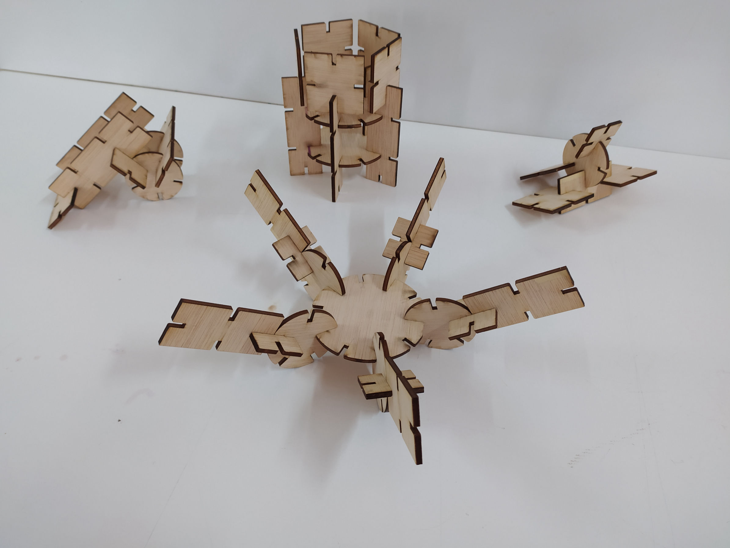
For the parametric desighn assignment, I used Grasshopper and Rhino. The process in the biit complicated, but after a while exploring and tweking it, it was really fun. I learned it from a youtube tutorial and then changed it.

Basically the process is to create the notch to be used, link it to a curve in grashopper and this in turn to an object that is created, in which the parameters can be adjusted. Then decide the position and quantities of this notch in relation to the object, and the number of objects that you want to have in a certain space arranged in the form of a mesh. Then you must bake the file to Rhino and you're ready to export for cutting.

  1. First you have to create on Rhino the kind of notches you want, and for that you should take in count the thickness of the material and also it's rigidness, because it works pretty different in cardboard, wood or even acrylic for example. For this project, after some test, I used common rectangles with a little chanfle on the edges.
  2. In Gasshopper, first create a CURVE. We RIGHT CLICK on it and select SET CURVE from the menu. And we select in Rhino the notch we want to use.
  3. A good practice is to rename the things you add to Grasshoper so you know which is which.
  4. Create a BOUNDING BOX component, we connect the CURVE that has the notch to it in the CONTENT slot (C). RIGHT CLICK on it and select UNION BOX. This maps the geometry of the notch.
  5. Create a DECONSTRUCT BREP component, we connect the BOUNDING BOX  from the upper BOX slot (B) to it in the BREP slot (B).
  6. Create a EVALUATE SURFACE component, we connect the DECONSTRUCT BRE from the upper FACES slot (F) to it in the SURFACE slot (S). This will evaluate the pints in the surface. Add a PANEL PROPERTIES module to select the point in which you want the points to appear. {0.0, 0.5, 0.0}, and then you have to RIGHT CLICK on it and RE-PARAMETRIZE. That defines the UV parameters to be from 0.0 to 1.1
  7. Create a RECTANGLE object, and then add a domain with CONSTRUCT DOMAIN. This will generate an area around the object.
  8. Add a number value and connect it to the DOMAIN START (A) and DOMAIN END (B). After then RIGHT CLICK on the A, CLICK expression to open the expression editor and write -X, so that the values goes from negative X to positive X. Then connect it to the X SIZE slot (X) in the RECTANGLE.
  9. Repeat the instruction number 8 to generate the Y SIZE value. Whit that you will decide the sizes of the sides of the RECTANGLE.
  10. Create a EXPLODE component and connect the RECTANGLE (R) to the CURVE slot (C).
Mobirise

8 - Vinyl Cutting Stickers:

Created in Adobe Illustrator

DXF File

Silhouette Cameo Setting:

For the Vynil Cutting assignment I created the file in Illustrator and the cutted it in the Silhouette Cameo. The have a pretty neat website with tutorials on how to do everything with it.

Basicly, what you have to do is to place the paper or vinyl you want to cut in the cutting mat, unlock the rollers and add the material with the automatic controller by pressing enter.

In the Silhouette software adjust the setting of the size of material you are going to use and make sure your file fits on it.

Check the material settings in the software so that it matches the material you are going to use, the software comes with some pressets and that will also define the depth of the blade and the speed.

Check the calibration of the blade by removing the blade, putting it into the socket and turning it and there you will see the number in the side that tell you the size of the blade. Test in a corner before you send the whole cut because sometimes because maybe it it cutting to little or too much and then it will be dificult to peel or might damage the design.

Send the file to Silhouette to cut, and then after cutting remove the mat from the machine with the unload button and carefully pill the rest to have your cutted file.

NICE TUTORIAL:
https://www.youtube.com/watch?v=g1rNqPsCeFY

NOTE: The file needs to be an DXF file so that it doen´t has conflits with the machine. I tried with Illustrator and didn´t worked. Also have on mind that thiner, smaller designs are more dificult to peel.

Illustrator Design:

To design this file, what I did was taking a picture of a Tatoo I have, then oppen it in Illustrator, design some paths around it to create the vector with a black fill inside, check that the paths where closed, save it and export it.

9 - Reflections
and considerations: 

I really enjoyed this week, mainly because it was quite a challenge for me to use Rhino and also Grasshopper, since although I had once used 3D programs, I had never used these so I had to do a lot of research to understand how everything was done. , but in the end I already did it much more easily. Likewise, he had never used a laser cutting machine either.

I think it is very interesting how doing things in a parametric way works, since it makes it easier for you just to change some instructions, to be able to change your entire design, its size, the joints and others.

I liked this thing about making parametric toys, so much so that I even made them first out of cardboard, where I realized that the joints I had used, although they were very tight, were difficult after disassembling, and then I made them in plywood making new shapes and with other types of simpler unions.

The Laser cutter has turned into one of my favorite machines and I fell very confortable now using it and experimenting with it. I loved to test the flexible wood kerf, and I would like in the future to be able to do more testings around this or with new materials or even biomaterials.

The Vinyl Cutter process, although it is much simpler, I think it can have many utilities such as the one shown in the class of making flexible circuits, making screens for lithography or even 

Voltio

Mobirise web maker - Click now