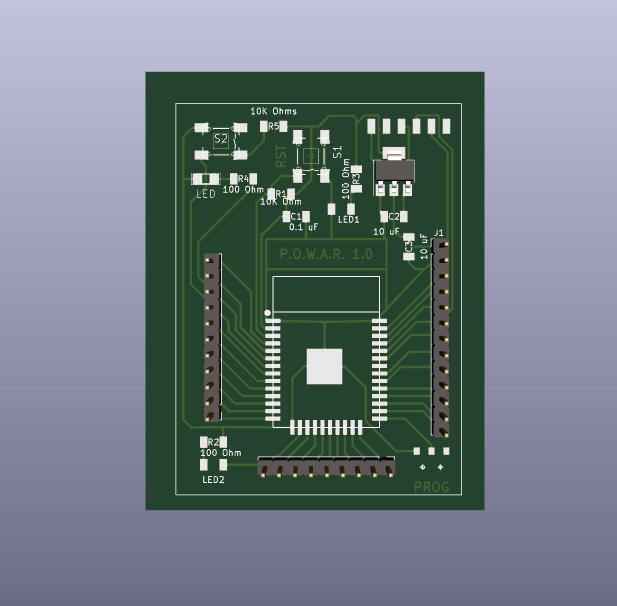
In this week we designed a Barduino, a development board with an ESP32 microcontroller on it that has Bluetooth and WIFi antenas embeded.
For this I used Kicad software and Adobe Photoshop.
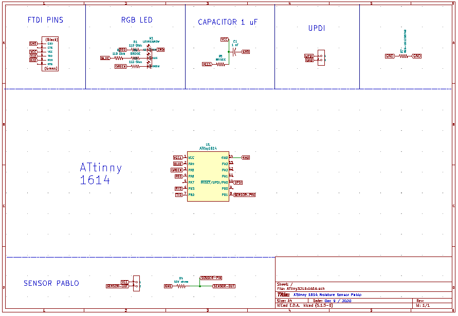
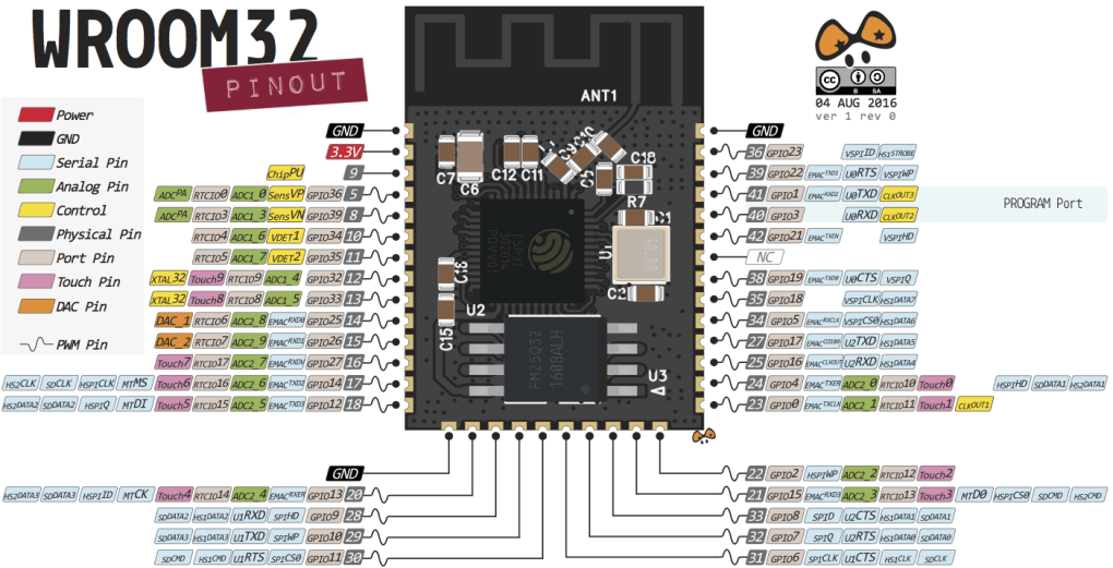
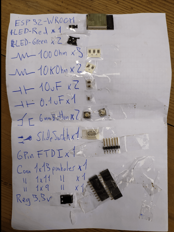
Something very important is to know the pinout of the microcontroller you are using and to check the datasheet of the components to see that you are using the correct resistors, capacitors or to know which pin is what.
KICAD FILES:
The first thing you need to do is to update the library with the components your Lab has.
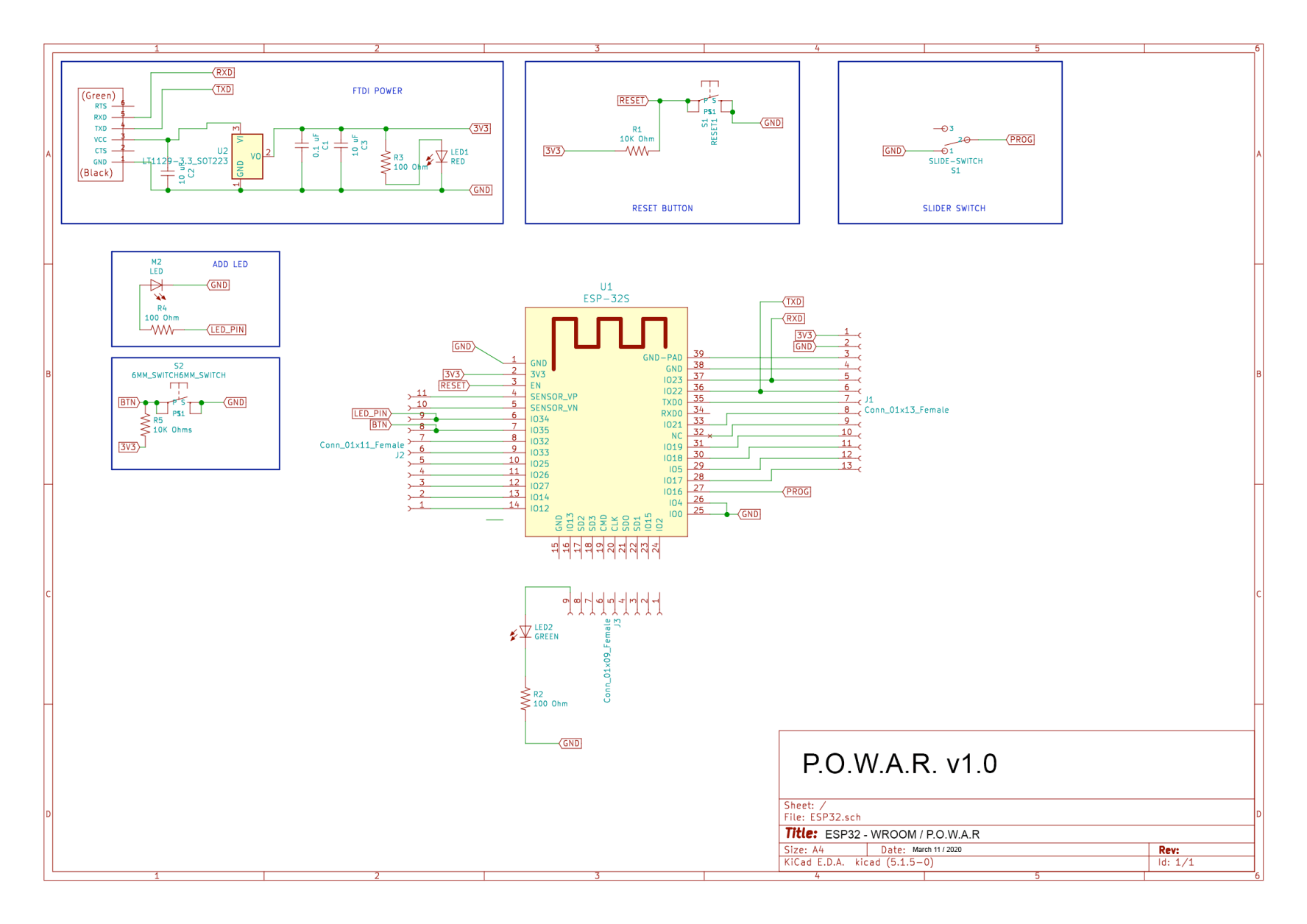
After that you should start designing the Schematics to decide how everything is connected. A good trick is to add tags instead of lines, so you can move them easier and have a cleaner design. This works also very well when a component could be connected to different places, like for example the GND or VOLTAGE.
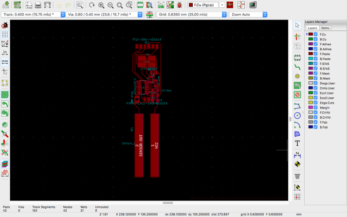
Then you need to generate the Netlist, which connects all the components and opens in the PCB editor... which looks like a mees in the beggining, but after you arrange everything looks pretty nice.
For mine, I tried to twist a little bit Edus design and changed the shape, it was pretty nice that after the process I shared the file with my classmates so some of them copied my alignment. You have to be also councious of the size of your board so that everything fits.
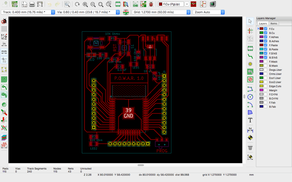

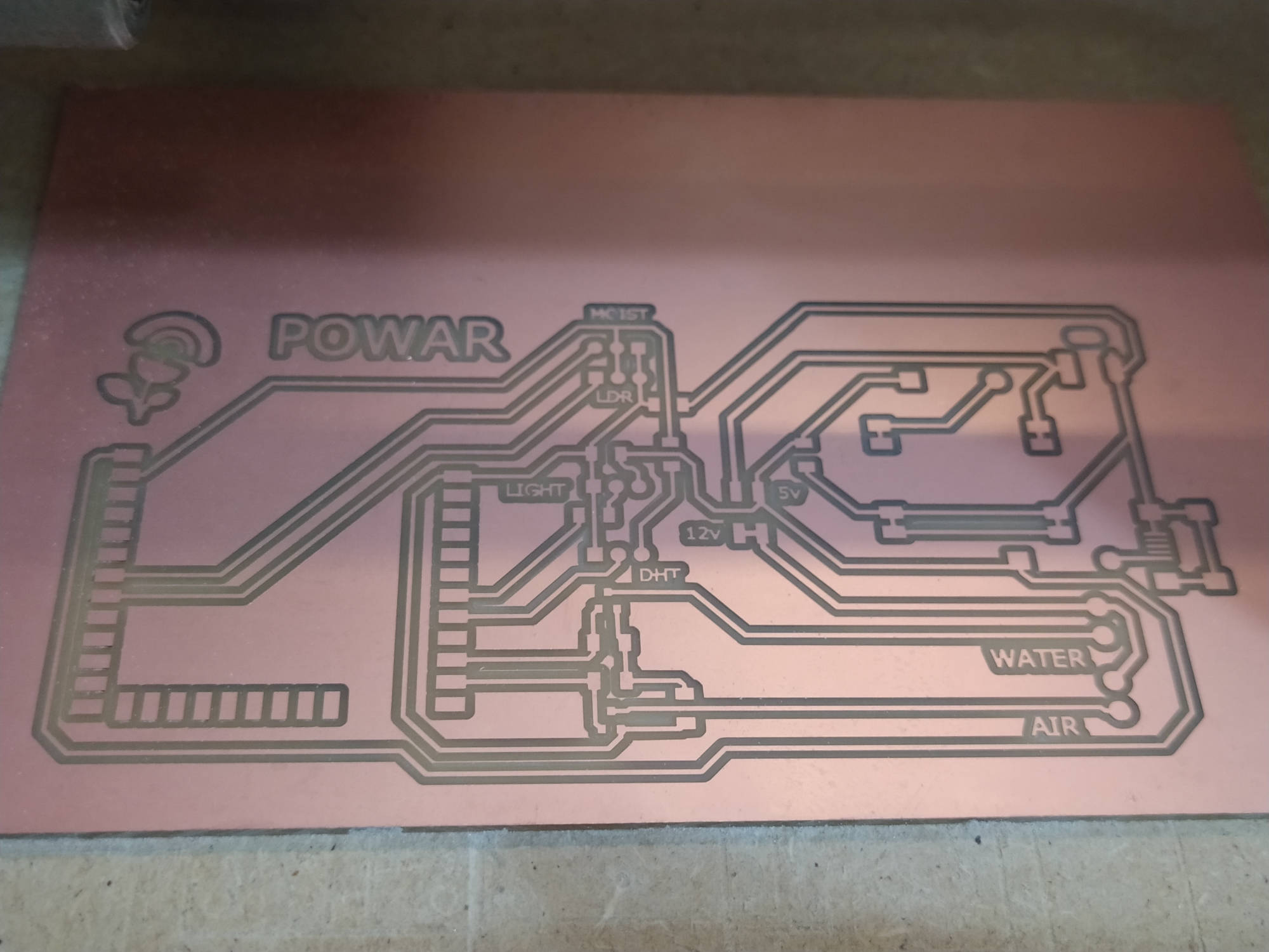
An important thing is to set properly the DESIGN RULES, so that the milling machine is able to properly mill the lines, if this is not properly set, some lines will disappear in mods. The vias Size should be 0.4mm This rules decide the distance of your milling, based on the size of your endmill and the infill.
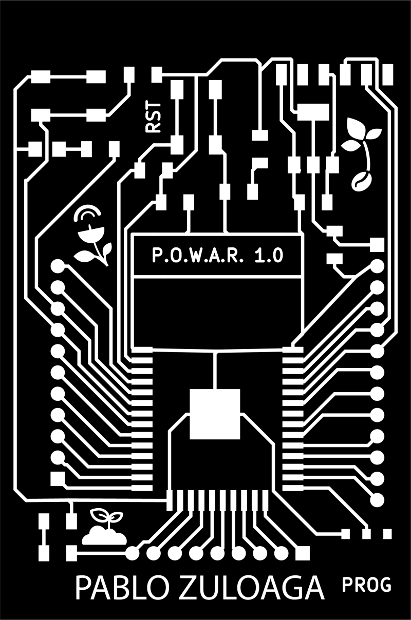
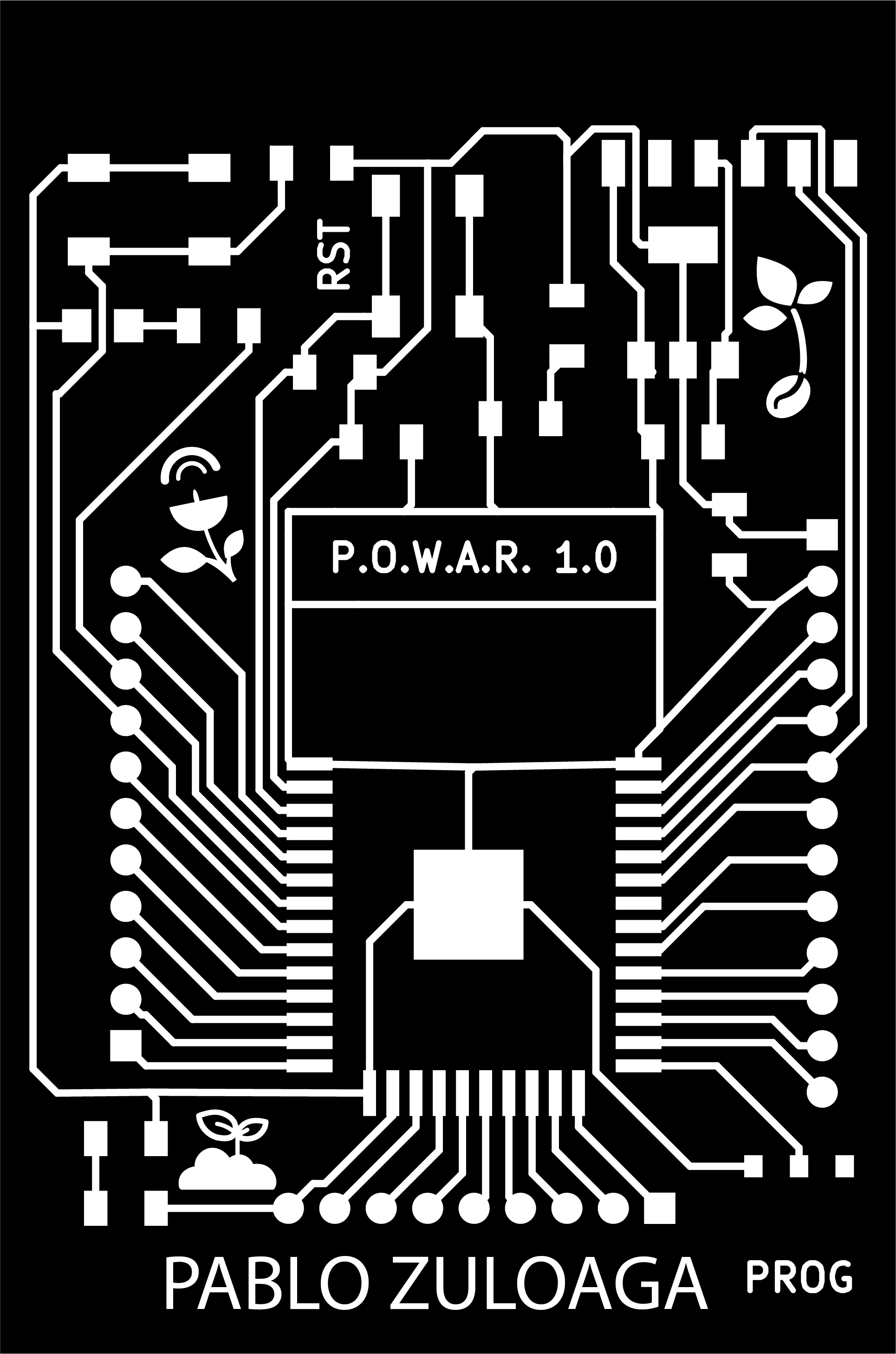
When I was done, I exported it to an PDF file to use it on Illustrator.
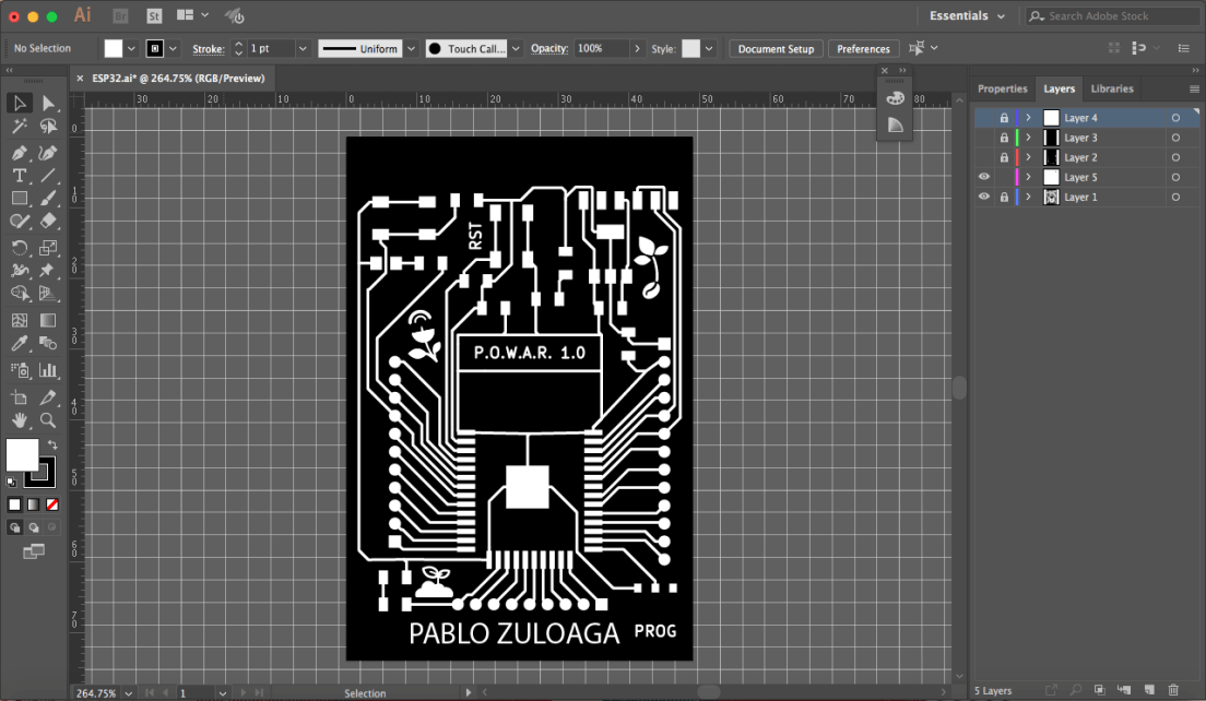
I used adobe Illustrator to generate the files, so I imported the PDF of the different layers. It´s better on PDF than SVG since the SVG has a problem with ilustrator because of the predefined thikness of the line, so you will se a big black circle if you import it. PDF keeps the file as it is. It is important to import it at an 1000dpi resolution.
Then I copied all separated files into a new one to check that all of them fit between them, after that I reduced the layer size to the size of the board and exported it.
ILLUSTRATOR TROUBLESHOOTING SOLVING:
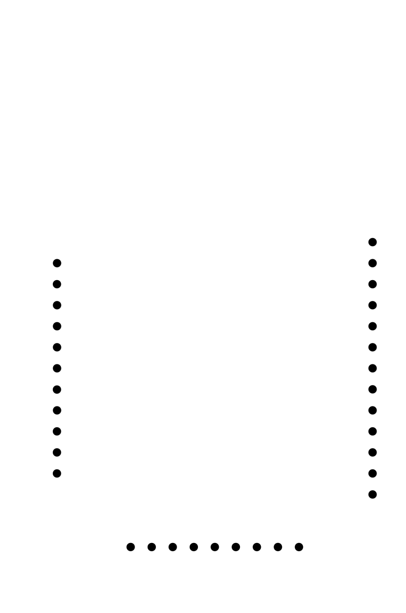
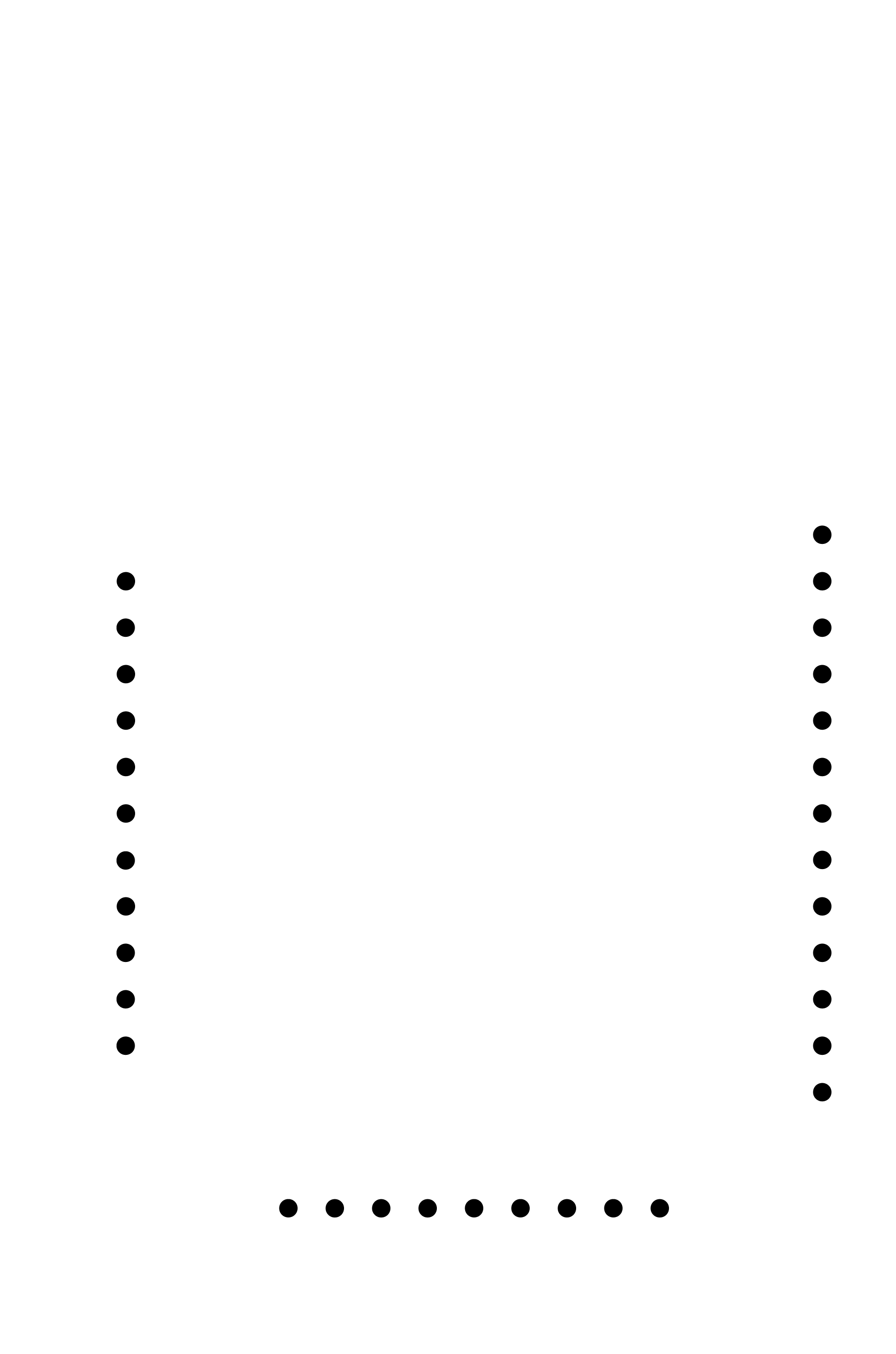
There is a problem when you do it in Illustrator and it is that you will have to generate the milling holes manually, because the PDF comes only with some white circles, so you will have yo measure the size of your pins, and draw some black circles in the middle of the white circles you already have.
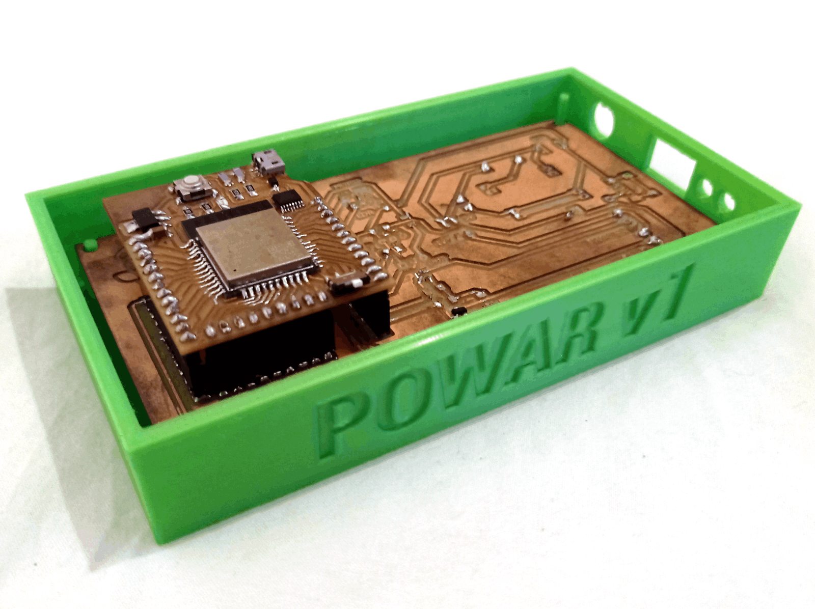
I also personalized my board a little bit by adding some designs to it in illustrator. I didn't generated an outline file, because I used the whole size of the board.
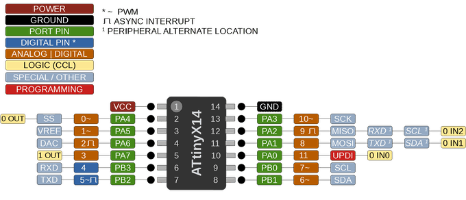

The ATtiny1614/1616/1617 is a member of the tinyAVR 1-series of microcontrollers, using the 8-bit AVR® processor with hardware multiplier, running at up to 20MHz and with 16KB Flash, 2KB of SRAM and 256B of EEPROM in a 14-, 20- and 24-pin package. (14 in this one). The tinyAVR 1-series uses the latest technologies with a flexible and low power architecture including Event System and SleepWalking, accurate analog features and advanced peripherals. Capacitive touch interfaces with proximity sensing and driven shield are supported with the integrated QTouch® peripheral touch controller.


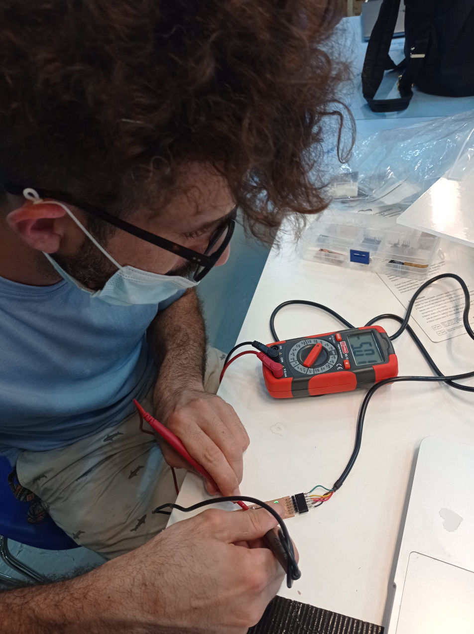
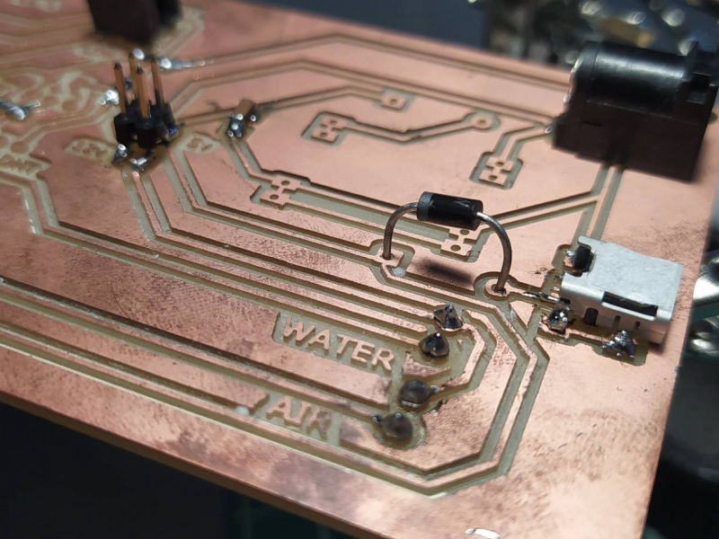
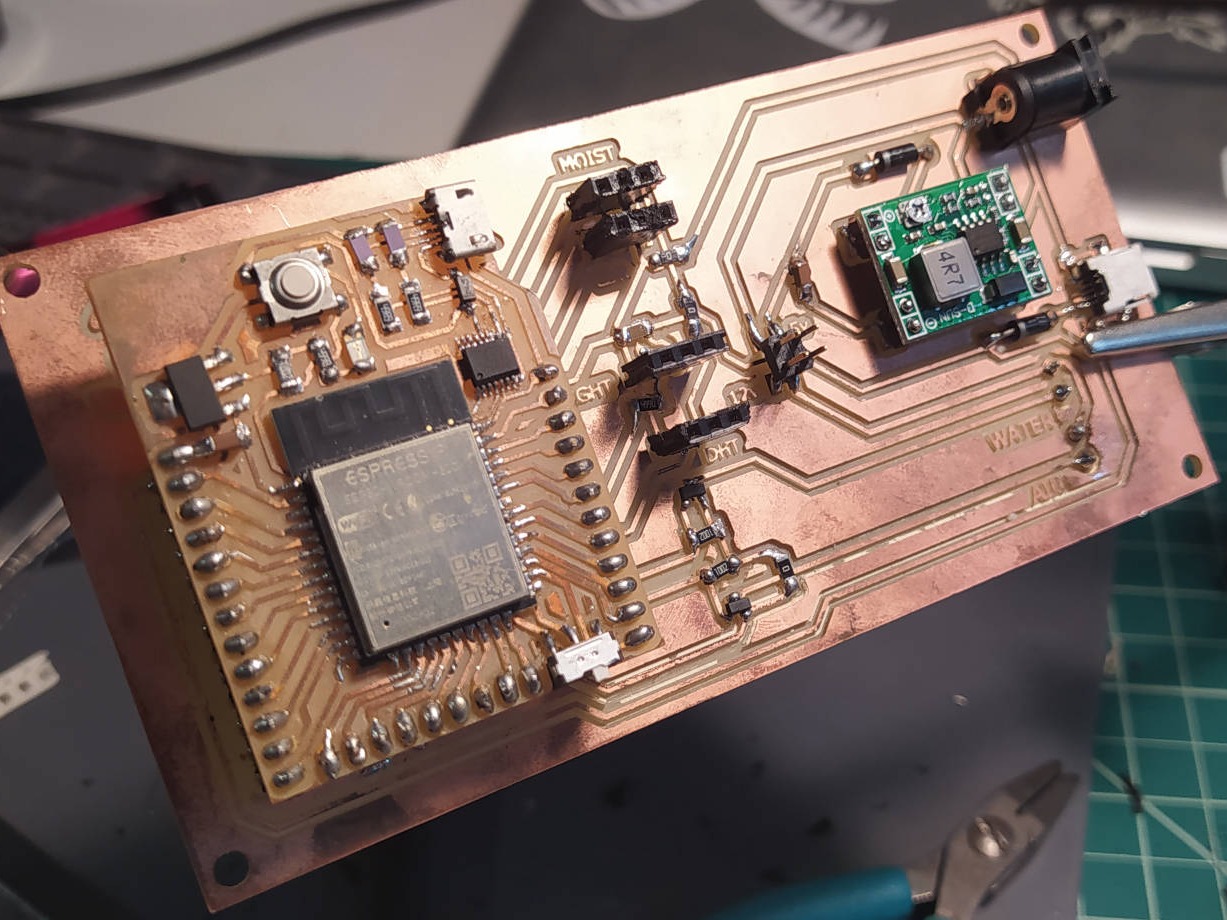
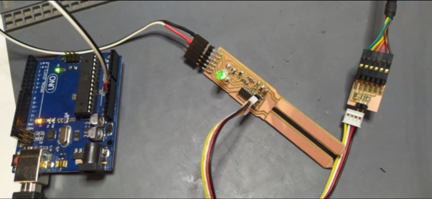
So finally, I tested the working
voltage and it gave me a value of 5.01 v.
For this, I set the multimeter for voltage testing (20v), and used the two tips to connect to the GND and VIN of the chip to check how much I was getting from the FTDI wire that was powering it.
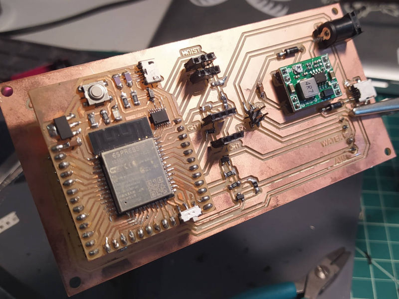
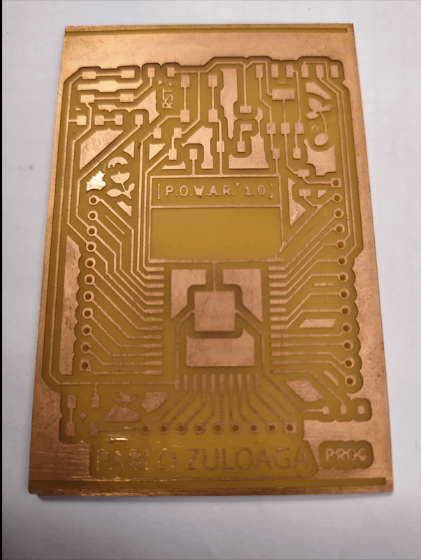
This has been one of the weeks or techniques I have liked the most. I believe that the SRM-20 is one of the machines I feel more confortable with, since I have done so many boards so far for my final project POWAR using different chips, designs and technologies.
I also feel pretty confortable designing the PCB with Kicad, but one of the next things I'll do is to also learn how to design with Autodesk Eagle, and also to prepare a Gerber file for massive production.
I also want to try how the milling process works, with a low-tech machine like the 3018 MiniCNC.

The page was built with Mobirise