Fab Academy 17

Machine Design

The (killer) Tattoo
Machine (gun):

For this week, we need to design a machine with mechanical functions, which means it should use at least some gears in the process, and could also be programmed to be automated. So I started looking in the lab between different gear systems they have used for different stuff, and I found one that I liked because it could be used to create a "Tattoo Machine".

A Tattoo machine basically has a system with a motor, that moves back and forth a piece that holds the needle, so that was the system I was looking for. I already know that it would not be safe to try a tattoo machine on someone, so I will just create it as an speculative object for fun. Maybe I could add some brushed later, and use it as a painting machine instead of a tattoo one.

Since I created all this machine at home, I used the electronics I had, my 3D printer and reused some of the parametric wood pieces for the laser cut assignment to build it.

Mobirise

Gear System:

For my machine, the gear system I used consists of two identical gears that move each other in oposite directions, a gear that will be connected to the motor, ant the two legs that are pushed with a tip that holds them together.

The relation of toque and speed between the two identical gears will always be the same since they have the same amount of teeth and the same diameter, but what will affect the speed or torque will be the relation between the motor gear and one of the identical gears that will be pushed. The identical gears dimensions will affect the amount of movement of the legs and the tip, because it is related to the diameter of the gear, so for a tattoo machine, ideally I would need two small identical gears, but the bearings already take 22mm, plus the double of size of each teeth (two sides), plus the space needed for sturdiness and to attach the legs...

A bigger motor gear will give more speed, but less torque, and a smaller gear will give less speed since it will have less teeth than the bigger in each turn. For a tattoo machine you want everything to be compact so you can handle it easily, but... this machine is made just for fun, not for tattooing anyone... for now...

I found a really interesting documentation about gears in this site:

https://www.precisionmicrodrives.com/content/ab-024-introductory-gear-equations/

Mobirise

Gears:

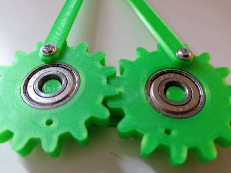
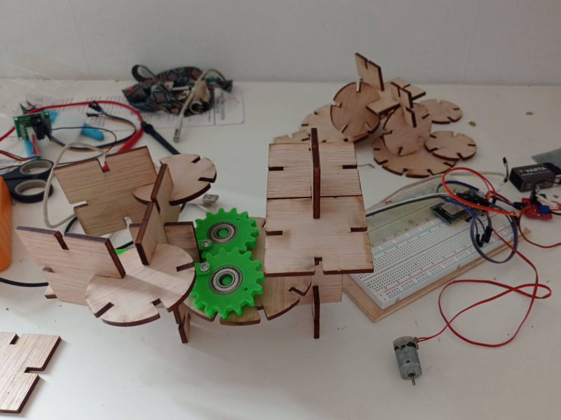
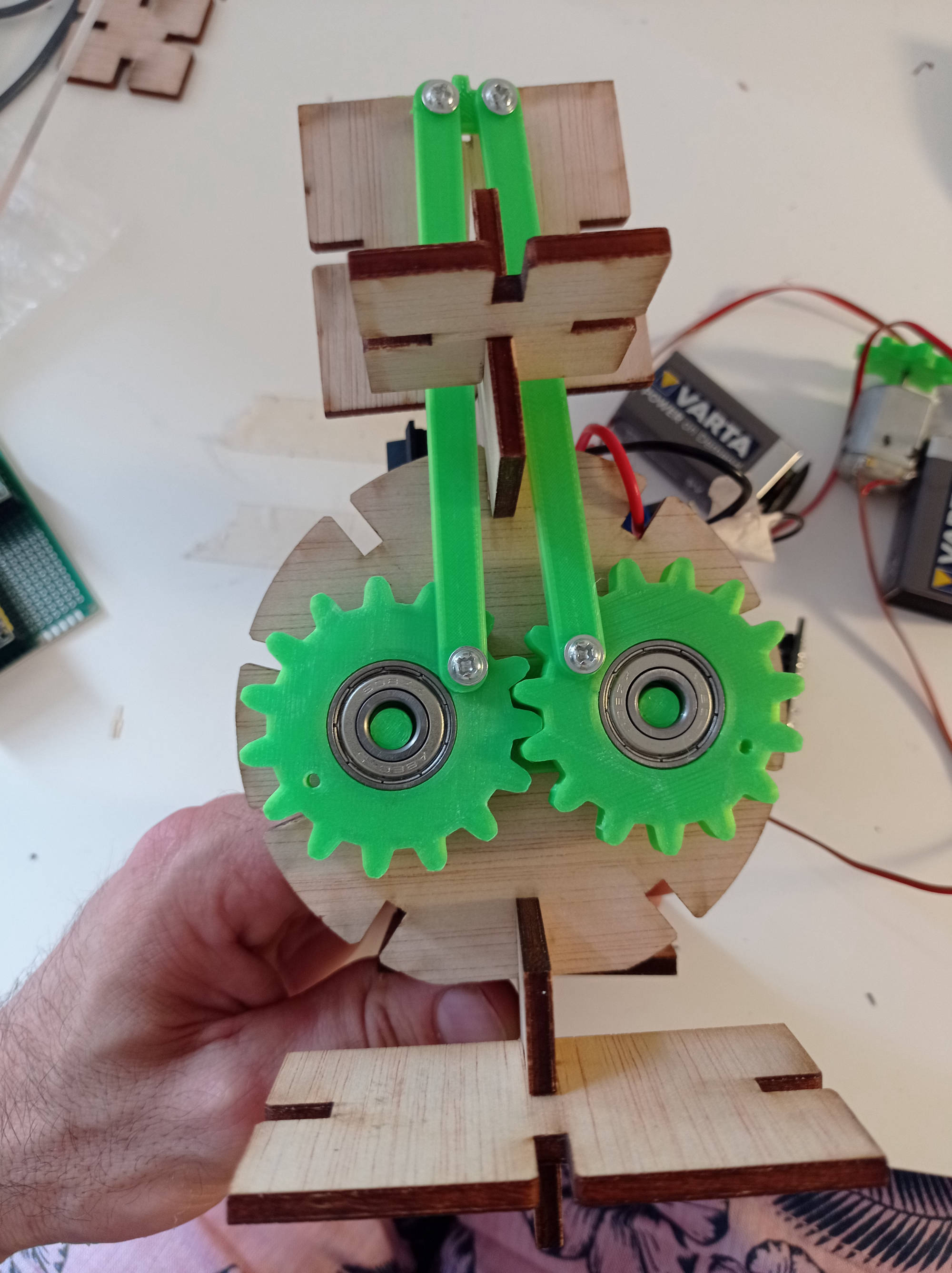
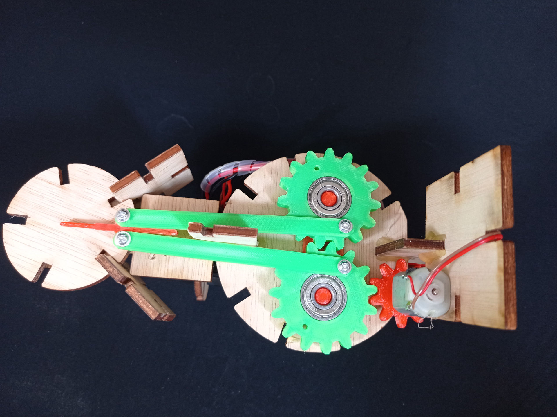
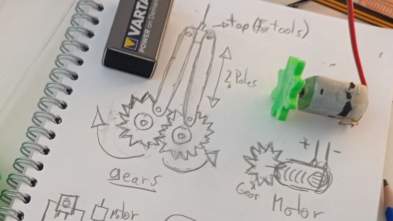
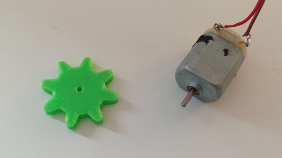
The first thing I did was designing the gears for the machine to print them on a 3D printer. So I followed this easy tutorial on how to create gears, and started designing the 2 main gears taking in count that I would add some bearings inside of them, so I should leave the empty space for them to fit perfectly.

Basically how I created the gear was by designing the shape of the teeth, and the desired distance to the center (radius), then I created a circular pattern with it, and added a circle in the middle and then extruded an joined everything together.

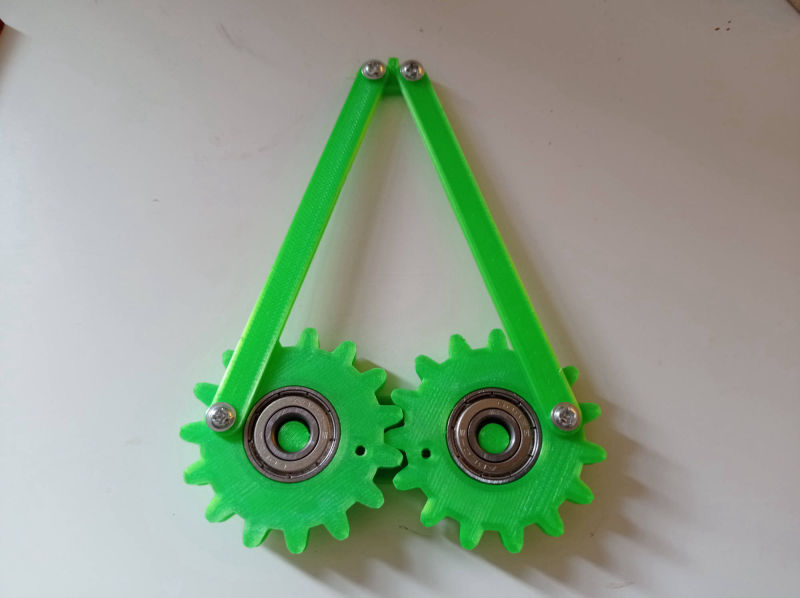
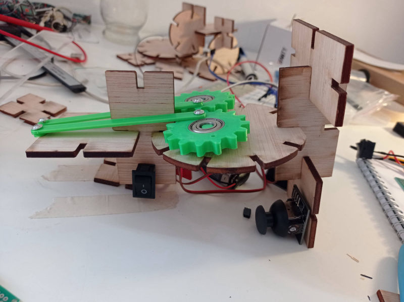
In the beginning I left the bearings a bit loose, so I did the piece that holds them again so they would be very tight, and therefore, the gears will move smoother between them.

BEARINGS DIMENSIONS:

IN DIAM:               8mm
OUT DIAM:          22mm
THICKNESS:      7mm


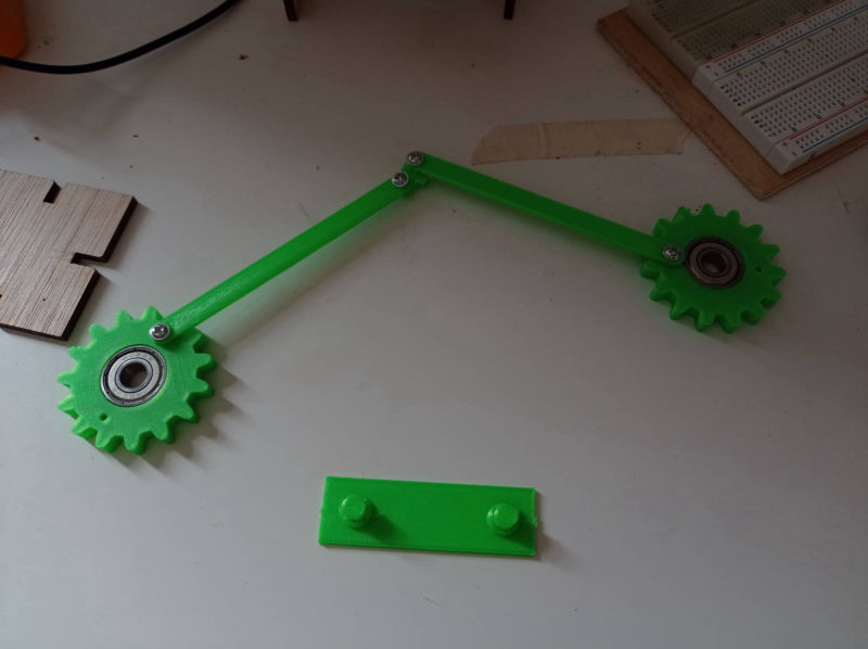
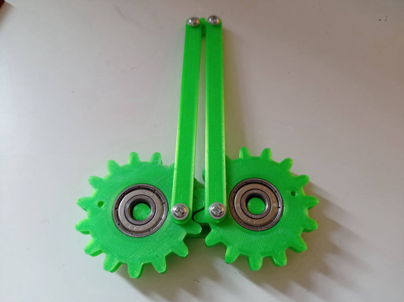
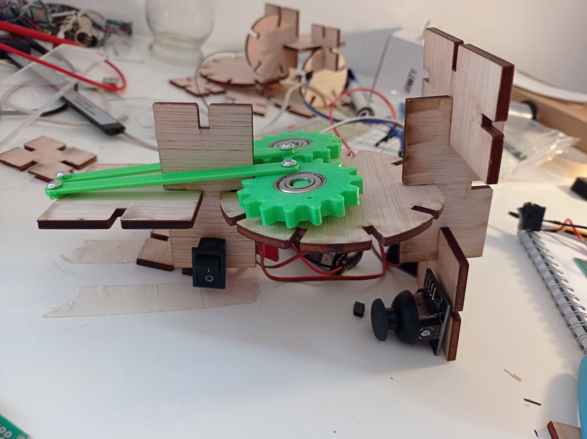
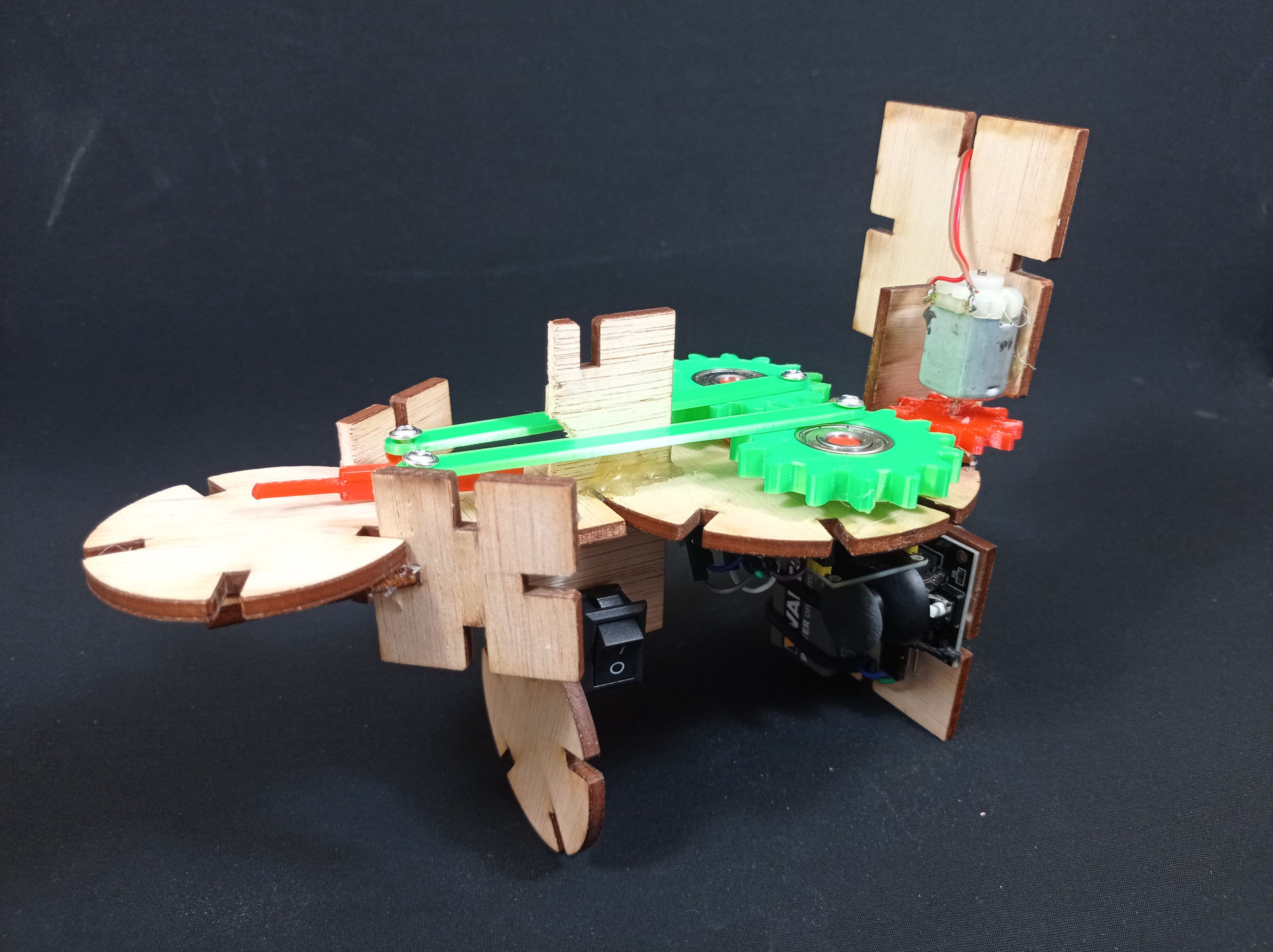
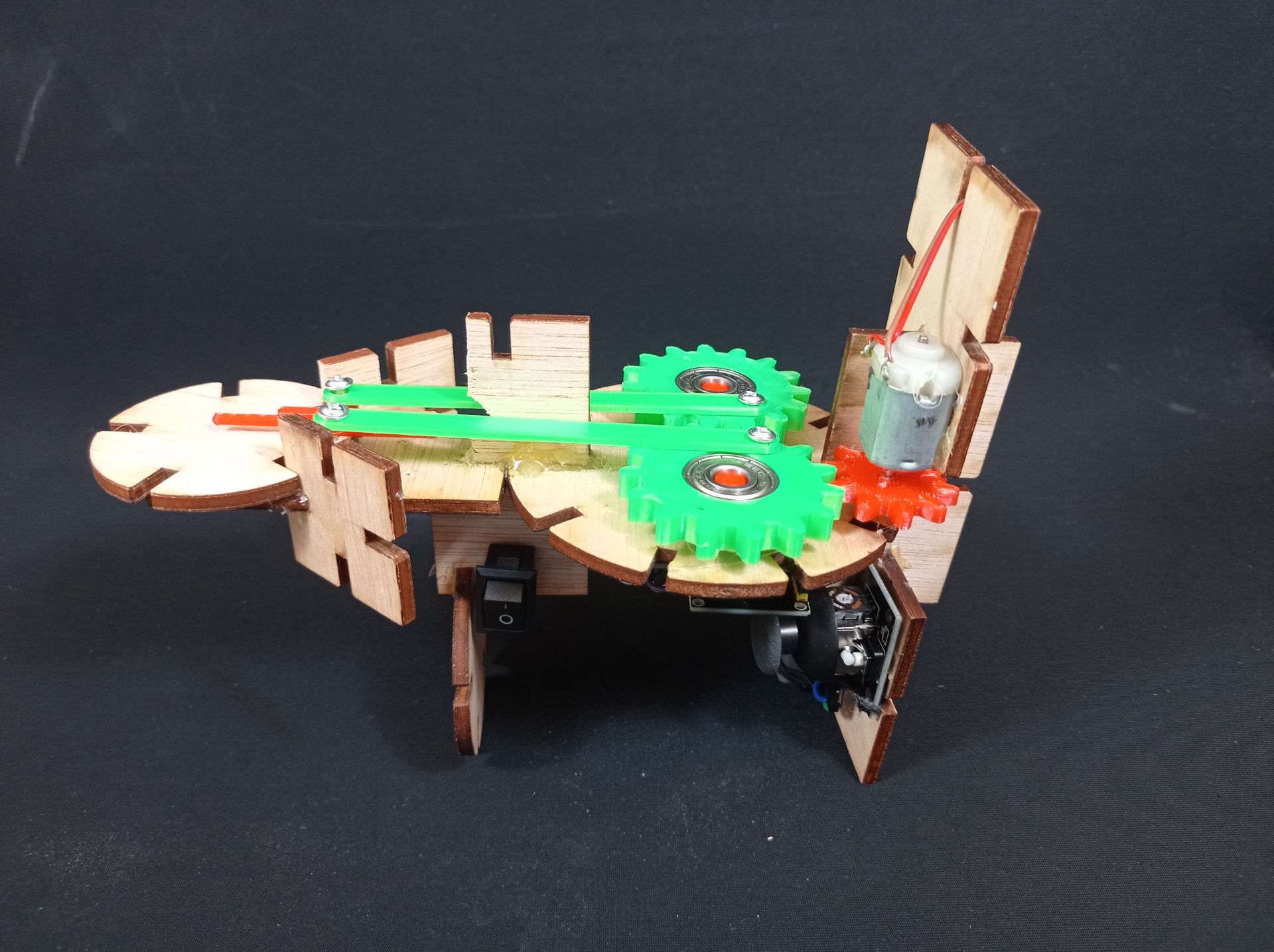
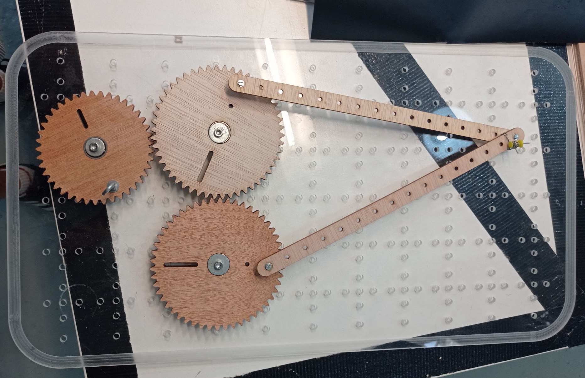
I was also going to need two legs, that would connect the two gears between them, and then a tip to add later another tool (needle, pencil, brush) that would be connected to the end of those legs.

I also designed a rail to keep the tip always on track, but in the end I decided to remove it because it generates a lot of friction. Anyway I will add the STL.


STL FILES:

Tatto_Gears_Base.stl

Tatto_Big_Gear_(x2).stl

Tatto_Small_Gear.stl

Tattoo_Arm_(x2).stl

Tattoo_Tip.stl

Tattoo_Rail.stl

Mobirise

Motor:

For the motor, in the beginning I wanted to use a stepper motor with a controller, but after some experiments, I figured out that the stepper would give me a pretty nice accuracy in measuring the steps and would have a good torque, but it would not have a good speed for the tattooing process. So after some experiments and Stepper Motor tutorials for ESP32, I decided in the end I would use a small DC motor.

Since I wanted to be able to control the speed of it, but the PMW pins of the ESP32 would not give me enough amps, I had to add a mosfet module so I could also have an external 9v Battery as the Power Source.

The DC motor has a very good speed, but now the problem is that it does not has much torque, so I have to be pretty careful of any additional friction that could be generated because that would probably stop the motor, force it or overheat the system.

This means that in a system (without any friction) the relation of speed between the motor and the tattooing tip would be something like this:

MOTOR RPMS:     16.000RPM
MOTOR GEAR:      8 teeth
ARMS GEARS:      15 teeth

16000 RPM * 8 = y * 15
y = (16000*8)/15
y = 8533 RPM

This means that without any friction, the nail will pinch you 8500 times per minute... something like 142 times per second!!!

(But the truth is that it has a lot of friction, so it moves a lot fewer times per second).

Mobirise
ESP8266 12-E Chip Pinout

Mosfet Module:

IRF520 Mosfet

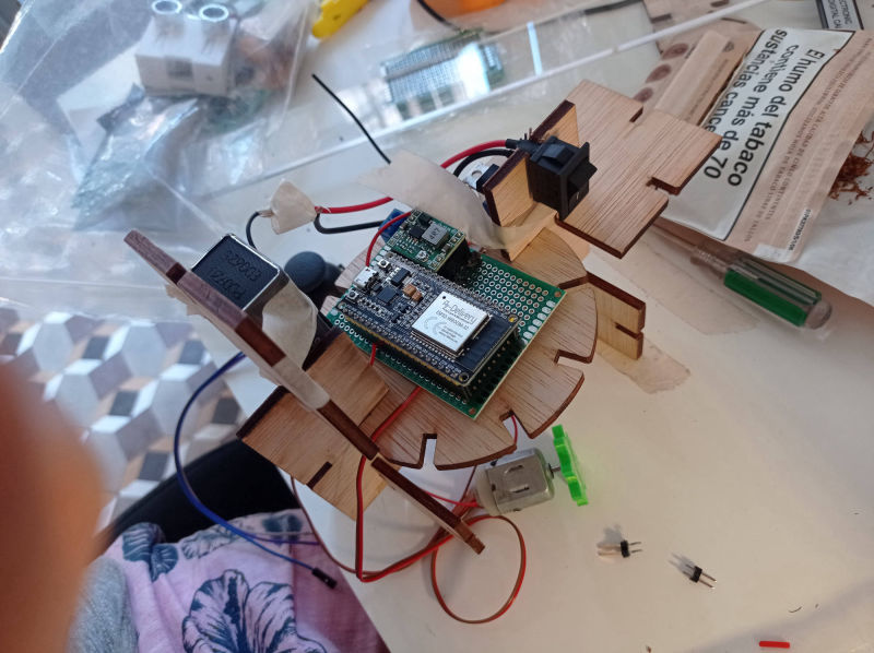
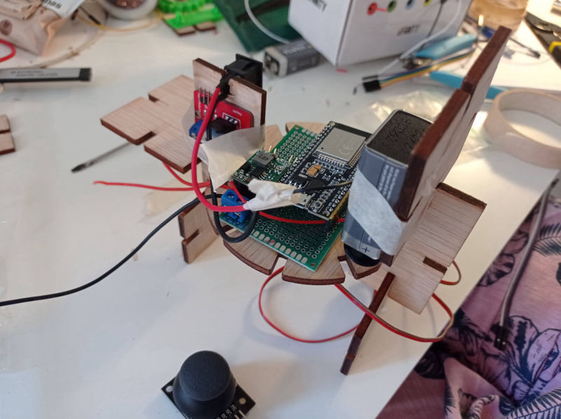
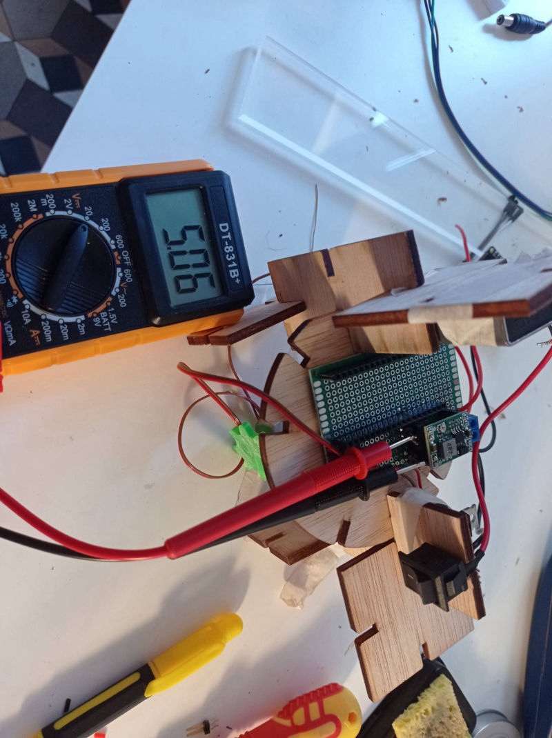
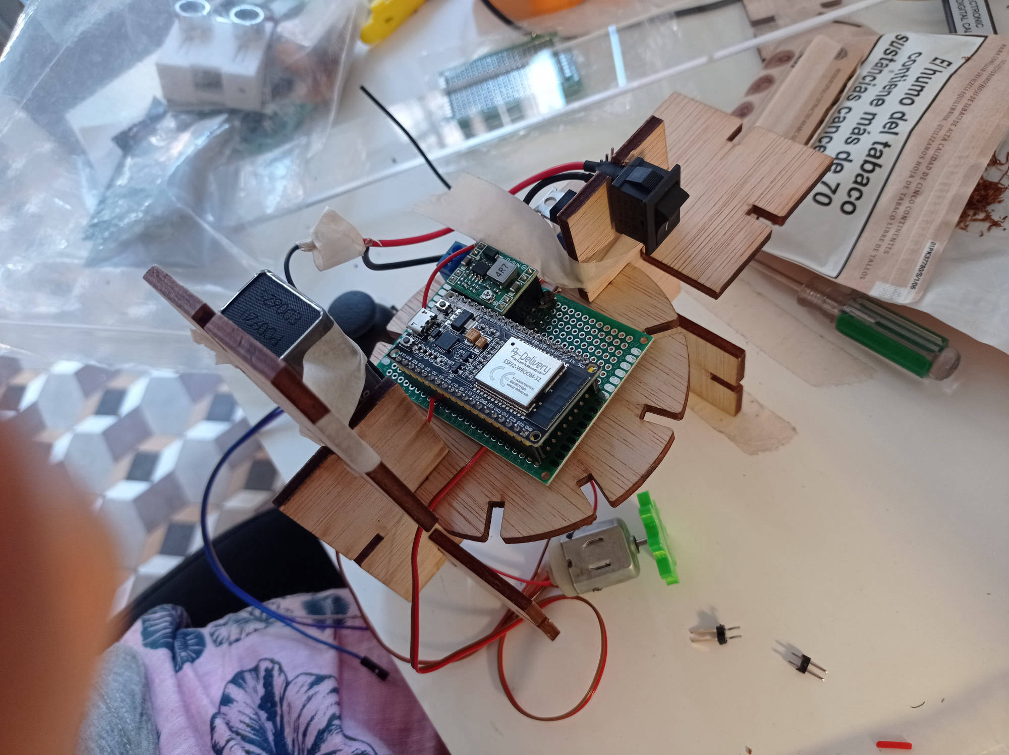
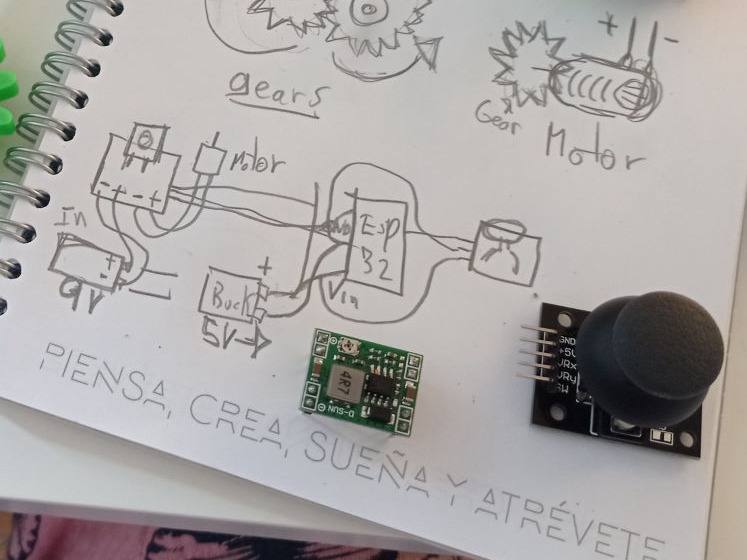
To connect the mosfet to my system, I followed the next schematic, but instead of using a potentiometer, I added a Joystick so that I could control the speed of the motor by moving one of it's axis.

Specifications:

1. Size: 33 x 24 mm.
2. Weight: 10 g.
3. Voltage: 3.3V, 5V.
4. Ports: digital quantity level.
5. Output charging voltage: 0 ~ 24V.
6. Output load current: <5A (1A above need to add heat sink).
7. Platform: Arduino, MCU, ARM, Raspberry Pie

ESP8266 12-E Chip Pinout

Joystick Module:

It is pretty straight forward to use, this one has X, Y and a PRESS BUTTON in case you want to use them, but for what I want, I'm just going to use the X axis pin.

The problem with this Joystick module in my opinion is the sensitivity and the range, because they are not pretty well calibrated, so it is har to "fine control" with them.

For the code, I just got the values from the analog reading of the VRx pin, and map it from 0-255 for PMW in the code which I'll describe later.

Mobirise

Electronic Board:

For this machine, I used an ESP32 commercial dev board, a Buck converter to pass from 9v to 5v to power the board and the electronics, a switch to control the main current that comes from the 9v battery, and a battery connector.

I mounted all of the electronics into a protoboard, and added some female pinheaders to easily connect the ESP32 and the Buck to the board, and some other mail headers to connect the motor and joystick to the board.

Mobirise

The Code:

The code for this was supposed to be very simple... ANALOG READ Joystick, ANALOG WRITE Motor... but the problem is that the ESP32 has no ANALOG WRITE function, because it has ADC pins, so instead I had to use the Duty Cycle and the ledcAttachPin and setup functions instead. Here is a link to the code where I learned how to do it, and my code:


LINK TO CODE:

///////////////////////////////////////////////////////////////
int Motor = 16;
int Joystick = 32;
uint16_t MotorDutyCycle;
const int MotorPWMFreq = 5000;
const int MotorPWMChannel = 0;
const int MotorPWMResolution = 12;
const int MOTOR_MAX_DUTY_CYCLE = (int)(pow(2, MotorPWMResolution) - 1);
const int ADC_RESOLUTION = 4095;

void setup()
{
Serial.begin(115200);
ledcSetup(MotorPWMChannel, MotorPWMFreq, MotorPWMResolution);
ledcAttachPin(Motor, MotorPWMChannel);
}

void loop()
{
int Jspeed;
int Mspeed;
Jspeed = analogRead(Joystick);
// Mspeed =map(Jspeed,0, 1023,0,255);
MotorDutyCycle = Jspeed;
MotorDutyCycle = map(MotorDutyCycle, 0, ADC_RESOLUTION, 0, MOTOR_MAX_DUTY_CYCLE);
ledcWrite(MotorPWMChannel, MotorDutyCycle);
Serial.println("MOTOR: ");
Serial.print(MotorDutyCycle);
Serial.print(" -- ");
Serial.print("\n");
delay(1000);
}
/////////////////////////////////////////////////////////////////////////////

Mobirise

The Assembling:

For the building process, I started thinking that, since it was too big to have the shape of a pen like most common tattoo machines look, I would laugh about the ridiculousness of the machine and wanted it to look more like a gun, where the joystick was something similar to a trigger. 

So I started matching the idea I had with the parametric pieces I had and the elements I would have to mount and the size of them, looking for the better way to build my "killer tattoo machine".

I iterated the design many times and added the components with masking tape in the beginning while I figured out their better position for each one. I measured the wires and tried to leave the least amount of wire as possible to reduce space, and then covered them with a wire holder.

In order to use the machine, you would first need to press the Power Button so that the 9v starts passing to the board and the Mosfet. Then the Buck will receive the 9v and turn them into 5v to power the ESP32 DEV BOARD, the Mosfet and the Joystick. The Joystick and the Mosfet are connected to the board through 3 male pins that go to the VCC, GND and SIG of each one.

The Final
"Killer Tattoo Machine":

I would not say this is the final version, but at least it is for the moment of this documentation. The machine poorly does the work because it has a lot of friction, and therefore it wastes a lot of energy so the 9v batteries don't last much.

I think that with more powerful motors I could be able to add more torque which will make the machine stack less, and maybe in that moment I could also add the rails I designed so that it is always aligned.

During the building process I have spoke about a lot of learnings, but now I'm going to talk about some improvements:

- Joystick: Calibration is pretty bad, so maybe there is another kind of pressure (pulse) button that would let me vary speeds with it.

- Power Supply: As I mentioned before, the 9v battery literally "Sucks"!!! So I will look for a more Powerful source of energy that lasts longer, and that is also rechargeable.

- Motors: For the motor I would try with a higher voltage motor, something like 9v could go well, and also I want to experiment again with the stepper motor, since wight now I need more power than speed.

Voltio

Site was started with Mobirise