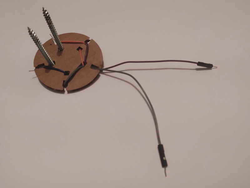
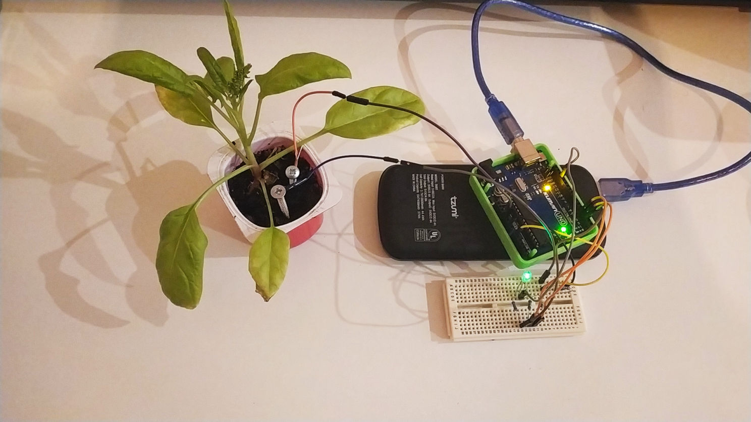
For this project I first tried to program a Soil Moisture Sensor (the one with two sticks) I bought to check the moisture of my plants soil by capacitive conductivity, which means that the amount of water between the two sticks generates certain conducticity which can be measured and then turned into an action.
The kit also comes with another water humidity sensor, that measures the amount of rain or reacts to when the rain falls. You can also use this one to measure the amount of wather inside a bowl, since it also reacts to conductivity, so the more water it has around, the more conductivity it has and therefore, more signal it sends. I dind´t used this one in my experiments anyway.

The first thing I did was to do a serial read to understand the values that it was giving me.
That showed me that the values ocillated from 0 to 430 more or less. 0 when it had no current between the two sticks (no conductivity), 400-430 when it was inside water or fully moistured soil, but there was another value when the soil was almost dry (similar to fingers conductivity) which was between 50 and 100.
SERIAL READ CODE

Since the values were around 400, I diveded them by 4, to turn them into an average percentage, for the Serial.printIn.
I wanted to check 3 values (Dry, Almost Dry, Wet), so I added 3 different color leds to my system (Red, Yellow, Green) with 220 ohms resistors.
I started tweaking the threshold code to set it up, so that each led lighted up when it was between a different threshold value.
I declared the main threshold to be 100, and decided that:
If the DATA was >= than (THRESHOLD + 200), the GREEN LED turns ON.
If the DATA was <= than THRESHOLD, the RED Led turns ON.
If the DATA was > than THRESHOLD and < than the (THRESHOLD + 200), the YELLOW LED turn ON.
And I added a delay to loop this process each 500 milliseconds.
I was having some troubles at he begining because I didn´t know how to have two conditions togheter like in the case of the YELLOW LED, so in some moment two leds where turning on at the same time, but I solved it with an AND code:
else if (data >= (threshold) and (data < threshold + 200))
I was also having troubles with diferenciating the conditions of the three leds, because I was only usinf IF code, but I solved it by adding somo ELSE IF.
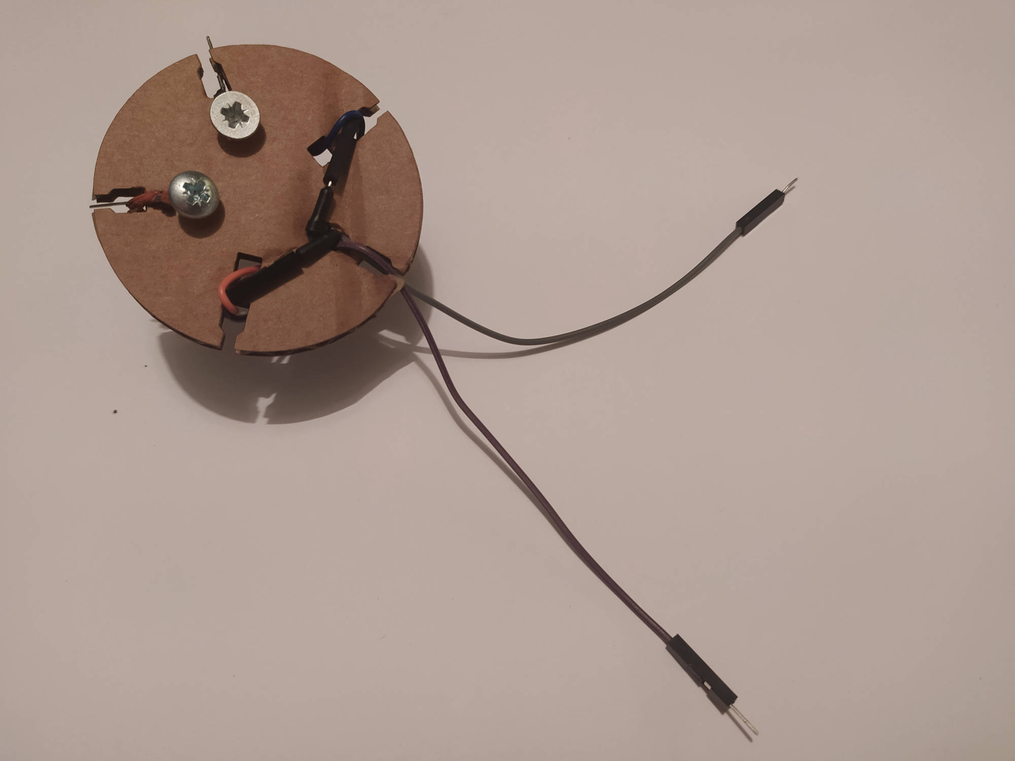
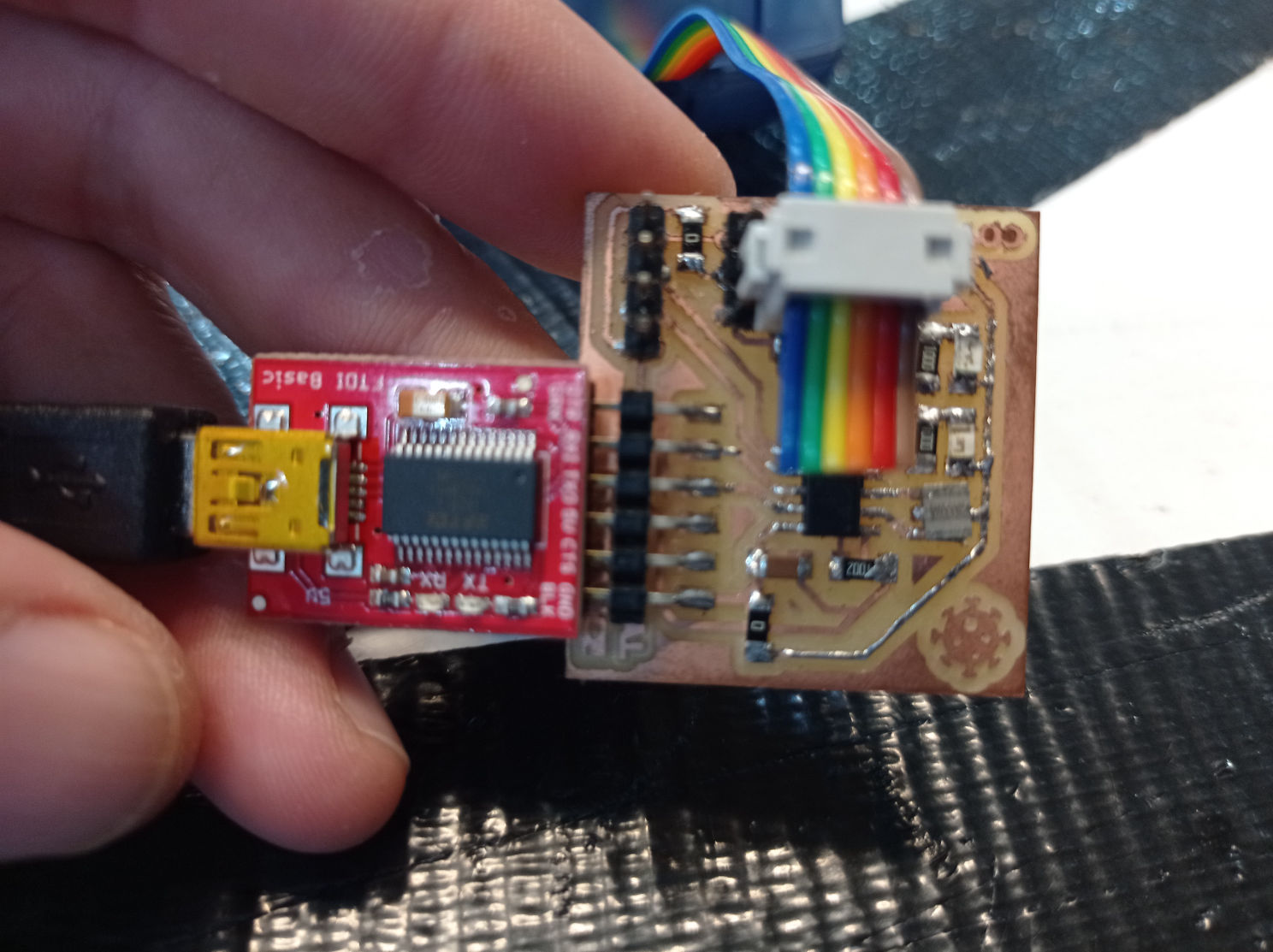
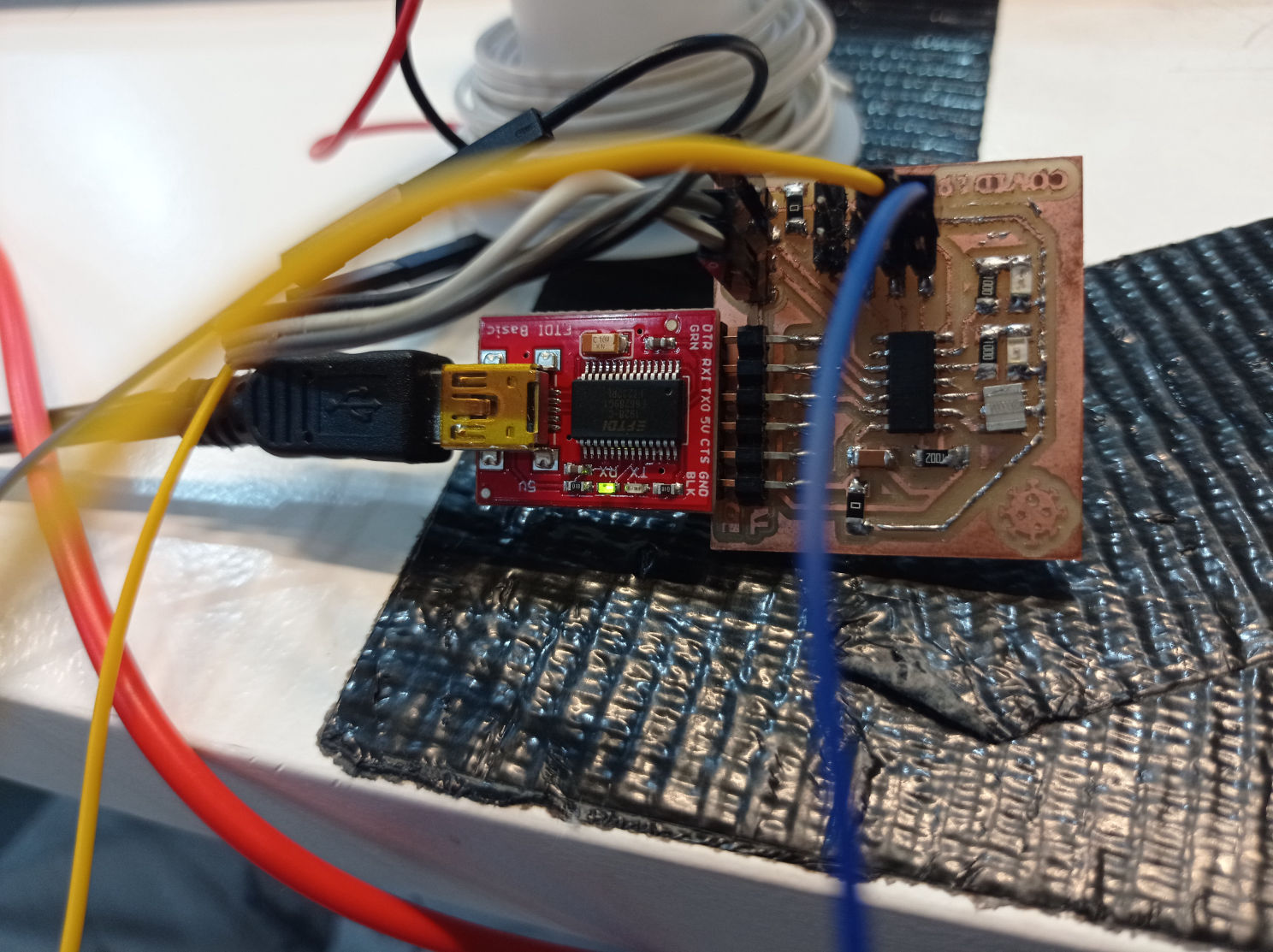
PCB Board Connection
(BOM) Bill Of Materials

3 x 220 ohm Resistors
1 x 10K ohm Resistor
1 x RGB Diffused Common Anode LED
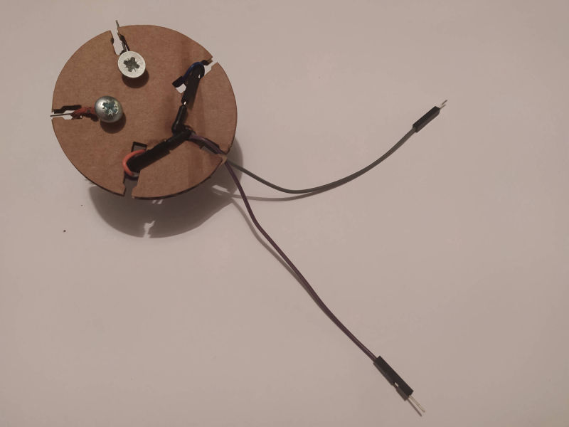
2 Bolts
8 x Male/male jumper wires
1 x Breadboard
1 x Arduino UNO (in this case)
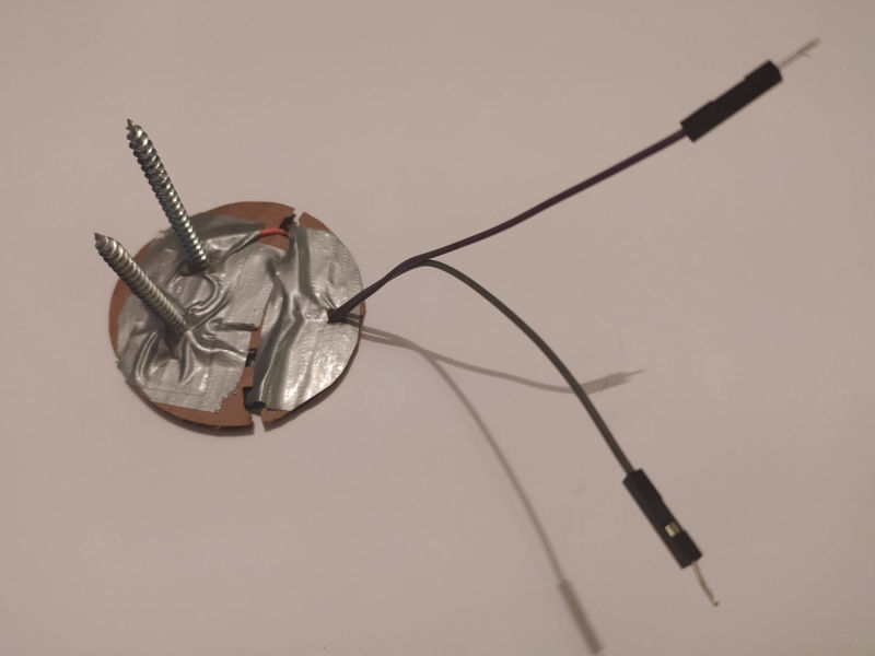
Sensor Optimization (optional)
Tape
Cardboard

The tutorial code differs from the one I used before, because:
- The type of led they use.
- How the translation of data into a percentage is averaged .
- The way they declare the ELSE IF and IF values.
- The way they set the values for TOO WET and TOO DRY.
My main learning from this code was that they declare two thresholds for TOO WET and TOO DRY, and for each led color they use s simplier function for them by just using <= or >= than thresholds. In that way they are able to leave the third LED option without any condition, so it will light with every data inbetween this two assigned conditions.
I really didn´t understood the code percentage operation, and I don´t know where these numbers they multiply and sum come from, so I changed the code
int percent = 2.718282 * 2.718282 * (.008985 * moistVal + 0.207762);
1) Read sensor totally dry (it should be 0)
2) Read sensor inside a water glass. (that should give you the highest reading)
3) Divide highest sensor read number by 100. (In my case it was 870/100 = 8.7)
4) Divide Sensor read in the code by the number you got to have a percentage:
moistVal = analogRead(moistPin);
int percent = moistVal/8.7;
Serial.print(percent);
Serial.println("% Moisture ");
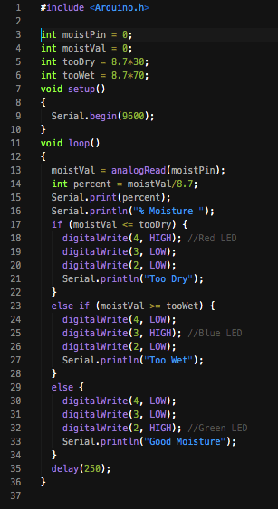
5) I also used the 8.7 I´ve got before, to declare what was to wet or too dry for me, and then multiply it by the percentage I wanted. In my case it is Too Dry if it is below 30% or Too Wet if it is above 70%:
int tooDry = 8.7*30;
int tooWet = 8.7*70;
6) I Also added a fancy Serial.printIn after each read, so that it tells you if it´s too dry, too wet, or good moisture.
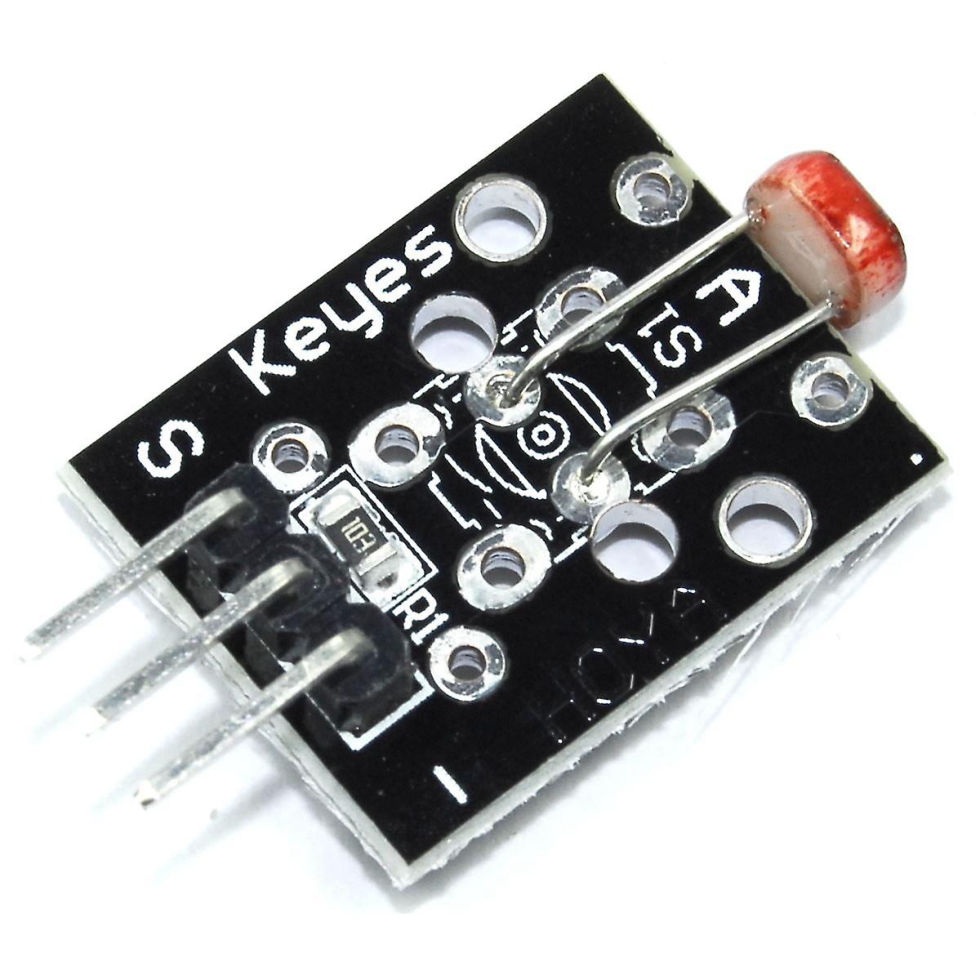
https://arduinomodules.info/ky-018-photoresistor-module/
Arduino KY-018 Photoresistor module, used to measure light intensity. It can determine the presence or absence of light.
This module consists of a photoresistor and a 10 kΩ in-line resistor. The photoresistor's resistance will decrease in the presence of light and increase in the absence of it. The output is analog and determines the intensity of light.
Operating Voltage: 3.3V to 5V
Type: Analog
When you use only the LDR, without being part of the module, you should always add a 10KΩ resistor that connects the GND and the Signal Pin.
The LDR Photoresistor has no polarity, so both legs work the same. Connect one of the legs to +3V3 and connect the other one to GND using a 10K resistor like if it was a wire, and also connect that leg to the GPIO A0 using a wire.
LEG 1: 3v3
LEG 2: 10kΩ to GND + A0 (or some analog pin)
Equation to calculate Resistance of LDR:
[R-LDR =(R1 (Vin - Vout))/ Vout]
R1 = 10,000 Ohms , Vin = 5.0 Vdc.
[Vout = ADC * (Vin / 1024)]
Vout = Output voltage from potential Divider.
SOURCE: Arduino Forum

#define LDR 2
#define REDLight 7
#define GREENLight 8
float LDRval = 0;
float sunny = 0; // calibrate sensor value WHEN LIGHT
float dark = 1024; // calibrate sensor value WHEN DARK
float treshold = 50; // define treshold to turn lights ON or OFF
#include
pinMode(LDR, INPUT);
pinMode(6, OUTPUT);
pinMode(8, OUTPUT);
}
void loop() {
if (analogRead(LDR) < 500) {
digitalWrite(7,HIGH);
digitalWrite(8,LOW);
} else {
digitalWrite(7,LOW);
digitalWrite(8,HIGH);
}
LDRval = map(analogRead(LDR),sunny,dark,0,100);
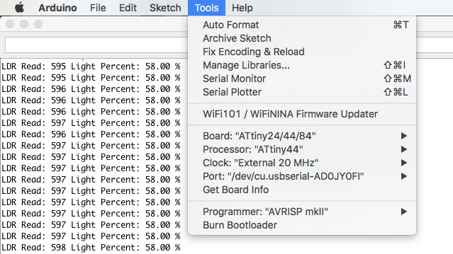
mySerial.print("LDR Read: ");
mySerial.print(analogRead(LDR));
mySerial.print(" Light Percent: ");
mySerial.print(LDRval);
mySerial.println(" %");
}

Built with Mobirise web page creator