Fab Academy 12

Interface and application programming

Interface and Application programming:

For this week, we needed to design an Interface or an APP to control some outputs in our board, or to be controlled by some inputs in our boards. An interface in basically the visualization in a screen that lets you control something or gather some information from something, that which you can actuate with through some buttons, sliders and more, or visualice what you are sensing through different kind of graphs.

From the plattforms we learnd, I experimented a little bit with the MIT APP inventor by creatting and APP to turn ON and OFF the R-G-B leds from and RGB single catod led. Then downloaded the APP in my phone and tablet and tried to control my NodeMCU with it.

I´m not going to go to much into deep in that one, because I basically followed Edus tutorial, and then twisted it a little bit to add more buttons, but I´m going to highlight some of the most important learnings I had from It.

I also tried to generate a visual interface that was controlled with a light sensor connected to my arduino or my mouse through the Processing APP, but what I did find more itneresting about this was the ammount of possibilities that processing gives you to do some creative coding and digital art. I really liked this APP a lot.

And my third experiment, which I´m going to talk more in deep in the Networking week, was designing a Dashboard through Node-RED, in which I can visualize and control some inputs and outputs, and is the one I think I might use for my final project.

MIT App Inventor:

MIT APP inventor is an easy to use APP generator software developed by MIT, which basically works like a drag and drop software in which you add the functions you want, and then configure and program the functionalities in a MIT Sketch way.

For this I followed Edus tutorial for the App Inventor class and modified it.

ESP8266 12-E Chip Pinout

ARDUINO CODE

The first thing I needed to do was to upload the code for the NodeMCU to connect to the WiFi, and declare in that code which are the ports I´m going to use as outputs, the serial BaudRate, and some instructions so that I can control the GPIO by simply accessing to HTTP server. So that deppending of how the website is written, it changes some predefined values.

One problem I had was that the starting code said I should load some libraries (WebServer.h, ESPmDNS.h) which I couldn´t find, so instead I uploades the ESP8266WiFi.h library, which made it work.

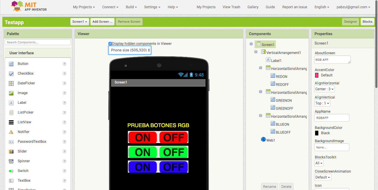
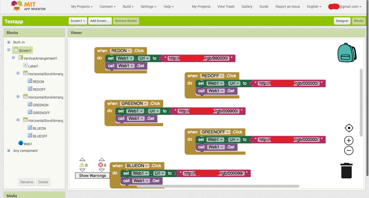
The Basic logic of how my HTTP server worked is like this, by declaring the amount of brightness you want for each led from 0 to 99:

* http://server_ip/rgb/rrggbb/
* where rr is the value set RED
* where gg is the value set GREEN
* where bb is the value set BLUE
* then terminate with '/'

So if I would go to:

http://My_IP/rgb/990000/
(Red Led Will be turned On)

http://My_IP/rgb/000000/
(All LEDs would be turned Off)

MY CODE:
ESP8266_HTTP_Server_RGB.ino

ESP8266_AppInventor_WiFi_RGB_LED.ino

Mobirise

MIT APP INVENTOR
DESIGN VIEW:

The MIT App Inventor is really easy to use, you just need to create a new project, define the size of the screen and start dragging the content into it.

In the DESIGN tab, is where you select all the content you want your APP to have like the buttons, the text, the title, images and more.

You have some Horizontal and Vertical arrangements in the LAYOUT tab that help you organice the content as you wish, and then drag the content into them.

One important thing if you want it to work with an HTTP server is to add a WEB option in the end of your design, from the CONNECTIVITY options in the left, and select to which IP you want it to connect, in this case is my IP, the same I declared in the Arduino Code. You could also use the options to connect it through serial or bluethoot, deppending of what you want to do.

Mobirise

MIT APP INVENTOR
BLOCKS VIEW:

The blocks view is where you code and configure the logics of your APP. It contains a lot of options, but one nice thing is that in the left side menu, it gives you the specific options you could control for all the elements you have allready added in the design stage.

Basically the sketch code I created what does is:

WHEN (color) BUTTON ON IS PRESSED:
    SET THE WEB URL TO BE THE ONE DECLARED IN ARDUINO CODE TO TURN ON
    CALL WEB GET

RED ON:
http://MY-IP/rgb/990000/

GREEN ON:
http://MY-IP/rgb/009900/

BLUE ON:
http://MY-IP/rgb/000099/

ALL OFF:
http://MY-IP/rgb/000000/

And the same process happens when I want to set it off.

When you are using a HTTP server, an other way to controll it is to just writte the HTTP instruction in your browser, and that will actuate in yout arduino (if it is connected to the web). But doing it directly from the web, I can even add more than this 3 options, since the arduino has allready been coded to respond from values from 0-99, what will give me a wider range of values.

For Example:
http://MY-IP/rgb/552010/

Prossesing:

Processing is a really interesting App to do creative coding. It gives you a lot of posibilities to visualize different thingg through coding. You can visualize a sensor, the mouse movement or other interactions. I find it really interesting for artistic purpouses.

For this I followed Josep Tutorials for Processing class and mixed and modified them. Ans also did some other tutorials I found on internet or in the software examples.

Mobirise

LDR Sensor Growing Ball:

DESCRIPTION:

For this project I mixed some learning I had from the  Josep tutorials, mixing the bouncing ball and the sensor read in one, and addig them some color changes.

This code makes a ball that grows and changes colors deppending on the LDR sensor reading.

Mobirise

3D Flying Mouse Map

DESCRIPTION:

For this project I followed a tutorial I found on the itnernet and mixed some learning I had from the initial Processing tutorials that appear on their page an Josep tutorial.

This code makes a 3D frlying map visualization that changes with the mouse.

Voltio

Web page was made with Mobirise