Fab Academy 7

Computer Controlled Machine

Make Something Big

For this week assignment, we had to make something big on wood, using the CNC. For this it was required to have Dog Bone Joints, since the CNC drill cuts a little bit rounded, so it doesn't makes straight cuts, so that makes this difficult to fit.

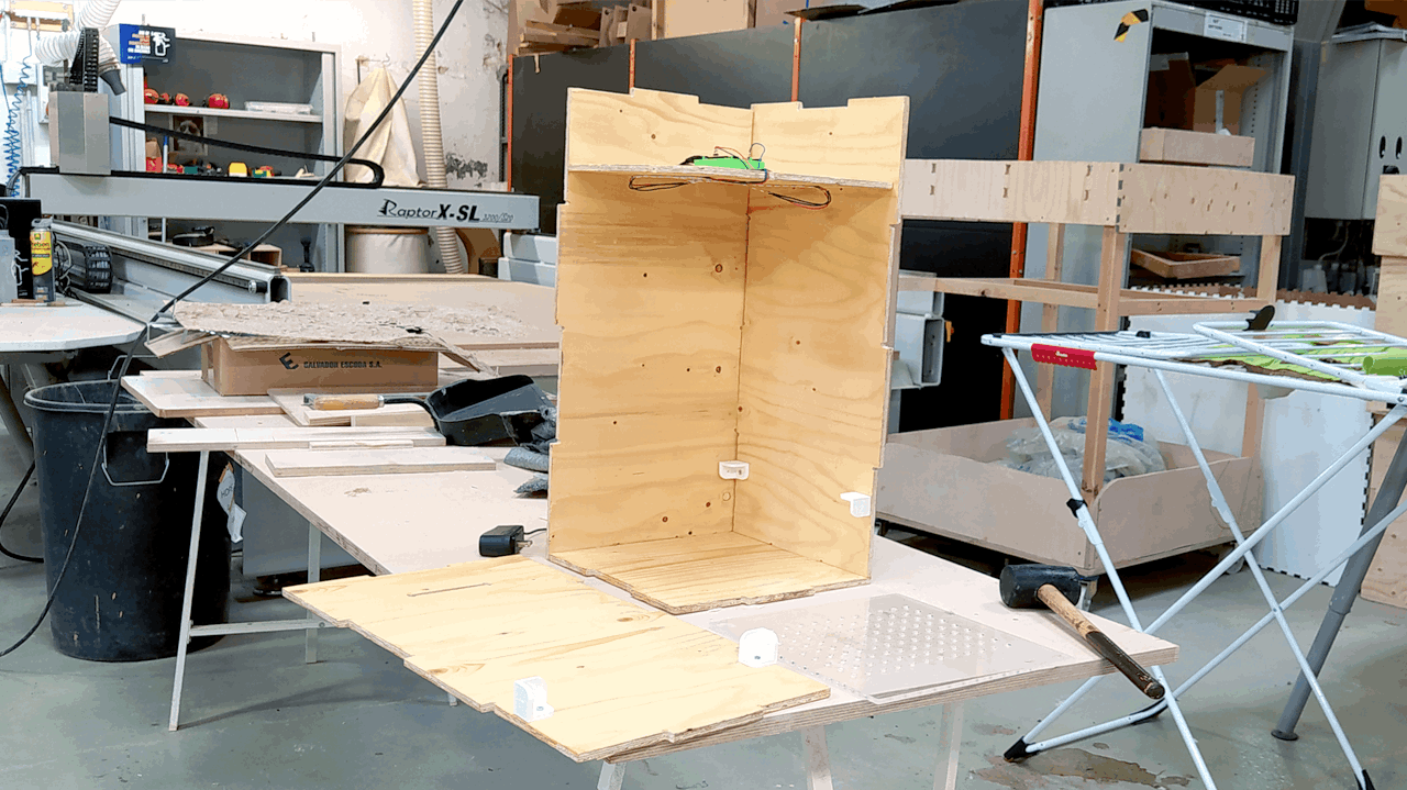
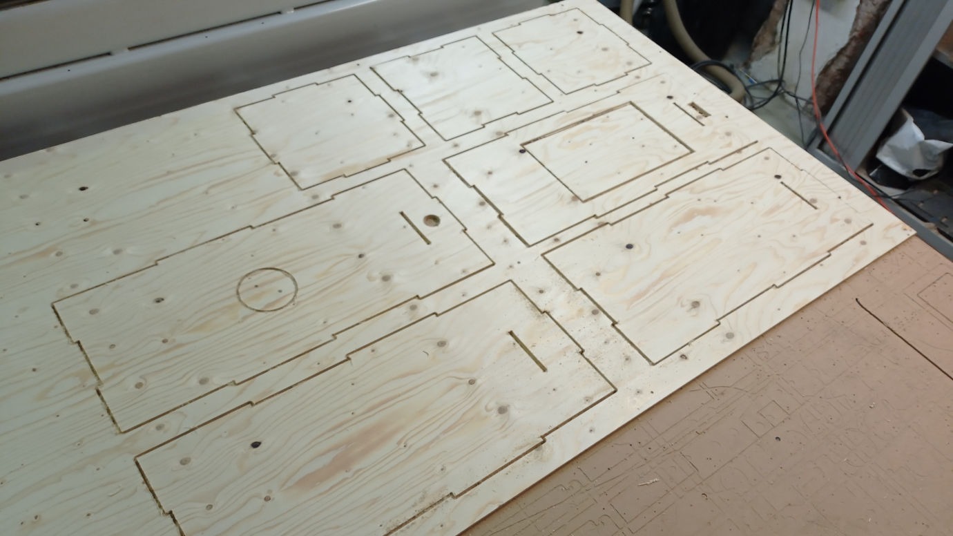
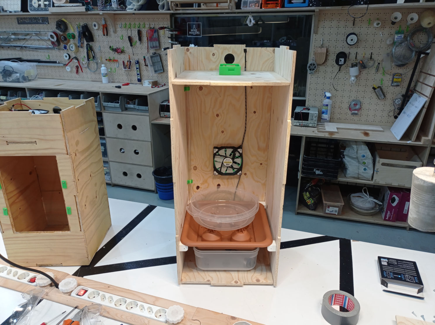
In the beginning (during lockdown) I designed a table and stool... but was never able to CNC it because of Covid. So when we went back to the lab, I has already designed the box of my project POWAR, and that was the one I finally cut on the CNC.

CNC stands for Computer Numeric Control, 

Mobirise
Mobirise

Dog Bone Joints

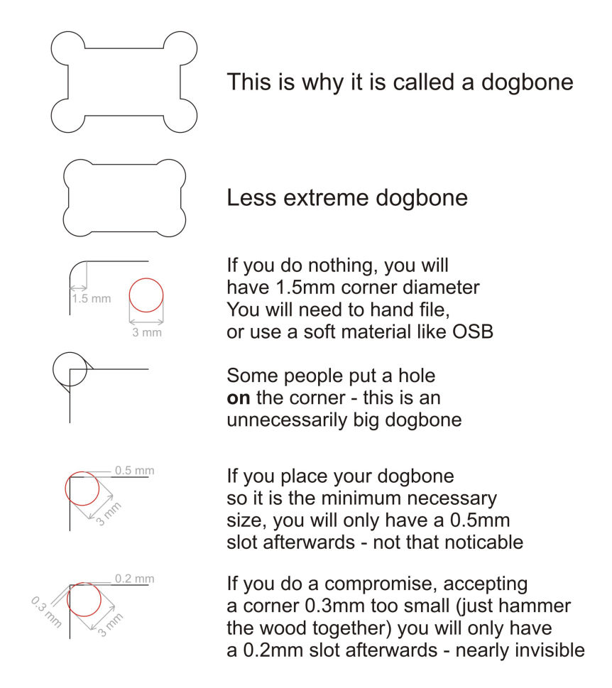
The Dog Bone joints, are called like that because they look like a dog bone, and the need of this in the design is because the CNC tool is rounded and not squared, so it will never reach a corner completely if not adjusted for that, so that will give you a bit of trouble if you are going to fit two pieces together because... they wont fit correctly.

I found a very nice explanation about how to make Dog Bone Joints manually that I will share below. 

Basically what I did was to create a cylinder with the diameter of the tool, and snap one of the borders to the corner of the object I'm cutting and then extrude it.

As it says here, you should also snap the center of the cylinder to the corner, but that will create a bigger unnecessary joint, compared to the smaller one I'm telling you which is much cleaner in the design.

After creating the cylinder, you can also mirror it to do exactly the same cut in the other side.

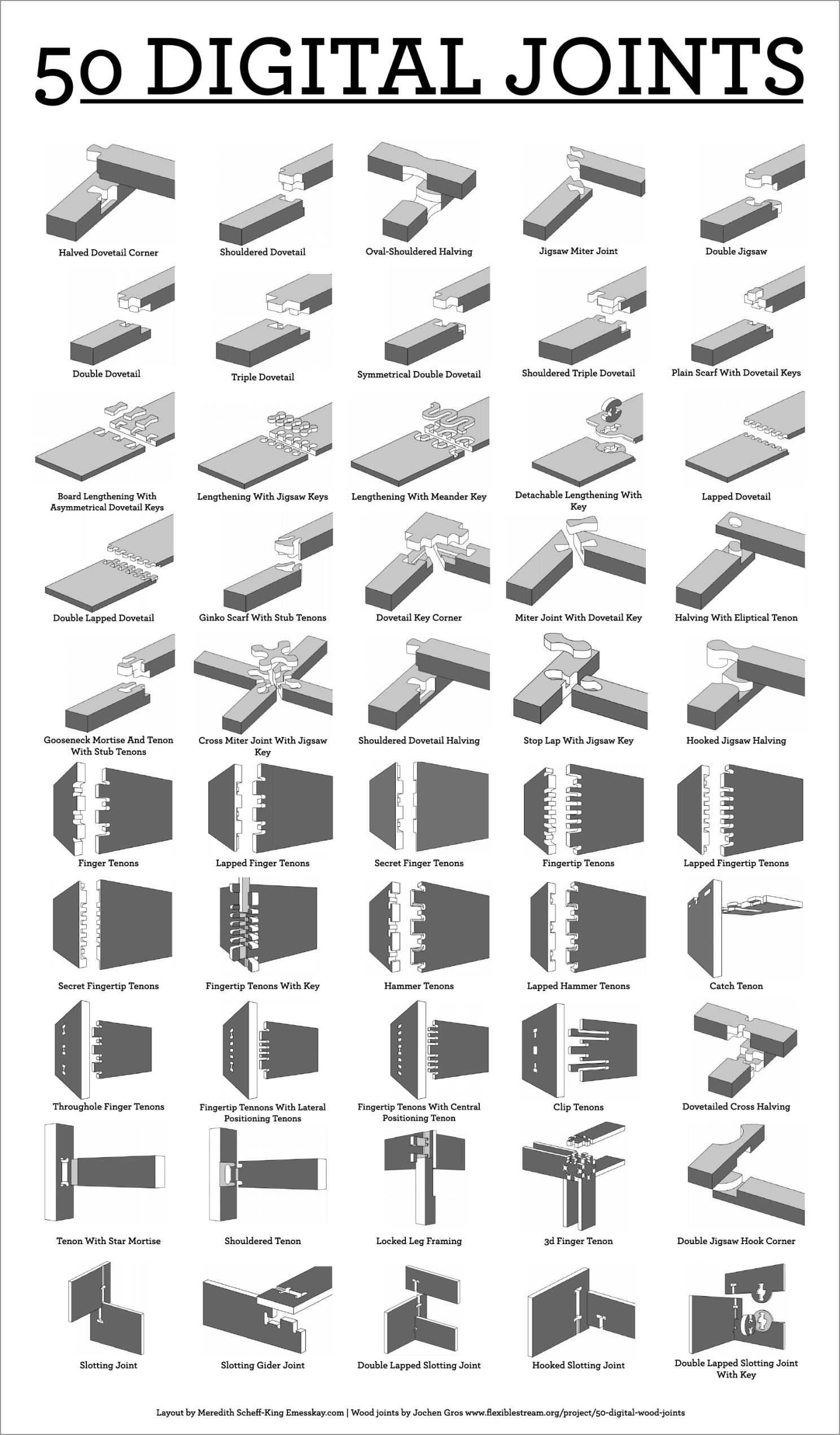
There are a lot more kind of press-fit joints, like doing them on top or in the side, but this are the ones I used.

*After I learned this I discovered that there was a plug-in in Fusion 360, that is basically a python code that does these joints for you. It kind of does the work, but it is not that good in the end. I will leave the link to the documentation and a youtube tutorial of how to use it in here.

http://tapnair.github.io/Dogbone/

Youtube Tutorial
Mobirise

For this project I followed a tutorial to create a stove in Fusion 360 and modified a little bit the measures and design, and then applied the learnings from the tutorial, to create my own desk with a Z shape on it because of my last name. As I was saying in the beginning, I never cut this one because of Covid, but instead, I cut the Box of my final project POWAR. 

In the same tutorial of the stove, they also teach how to do the dog-bones in an easy way.

Project Parameters

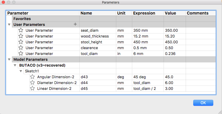
One of the most interesting things I learned in this tutorial is how to use parameters in my design to control different things like the thickness of the wood, the diameter of the tool (drill) I'm using in the CNC, the clearance I want to have in the cut, or even also some characteristics from the object like the height, diameter or some angles.

This helps a lot to make quick changes without having to redesign everything again, but instead just changing a parameter.
Mobirise

Setting the CAM Files

I could sincerely say, that this was the most difficult assignment for me, but not because of the assignment itself, but because the Rhino Cam software does not works on PC, reason why I had to learn it directly in the lab computers and I have only done it twice. That is why I will try to document it step by step, so that I don't forget anything for the next time I use it.
Mobirise
  • ***IN RHINO***
  • 1. Open file in Rhino.
  • 2. COMMAND> Rhino CAM.
  • 3. Rhino "Origin" is the same as the machine origin in this case: "X" is always the longest side.
  • 4. MOVE> take the corner to the origin (lower left)
            a. Select the whole material and press ENTER 
            b. PRESS:    0 > ENTER > 0 > ENTER 
  • ***IN RHINO CAM***
  • 1. Choose between MILL (cnc) & TURN (torno)
  • 2. In the "Program" tab you adjust, in the "Simulate" you can simulate the work before doing it.
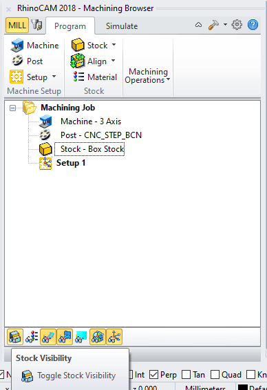
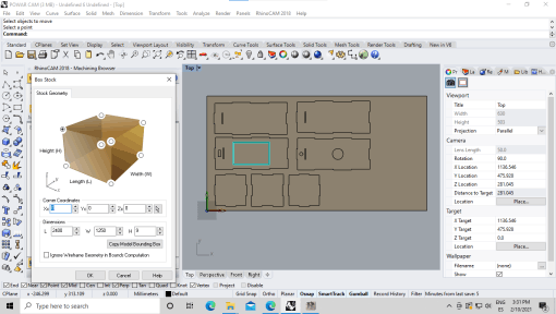
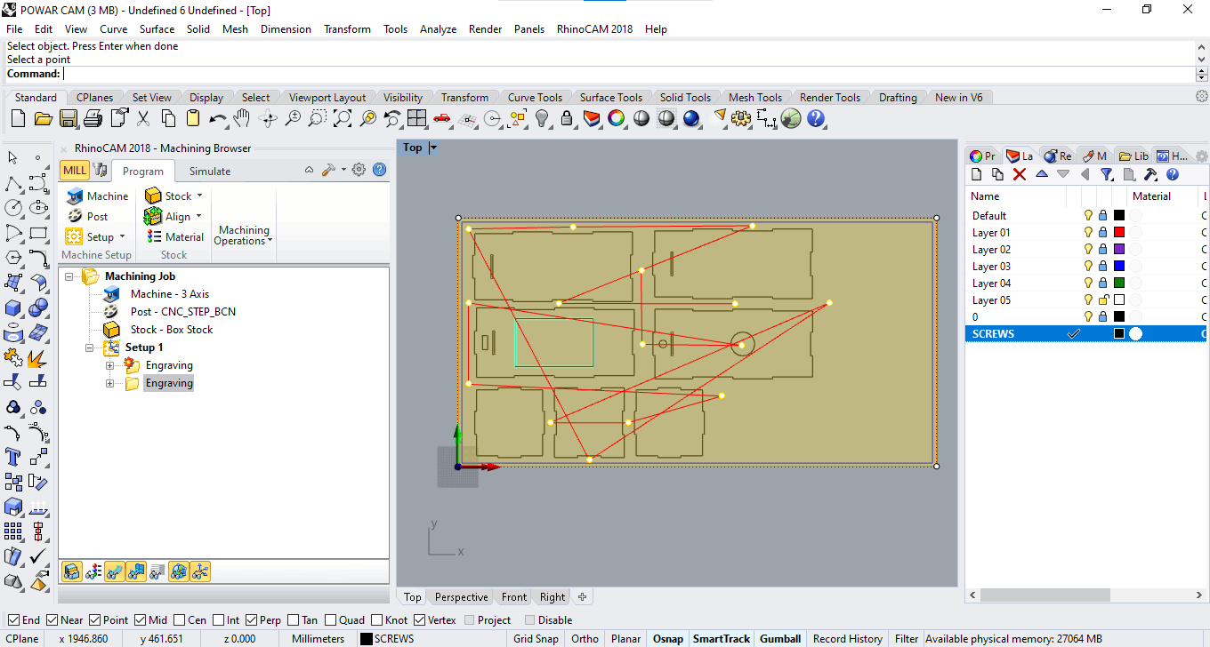
  • 3. In stock, I define the Stock material > BOX STOCK
                a. The material origin is the top (lower left corner).
                b. That is point 0, 0, 0.
                c. When you define the Stock, it turns yellow.
                d. Habilitate "stock visibility."
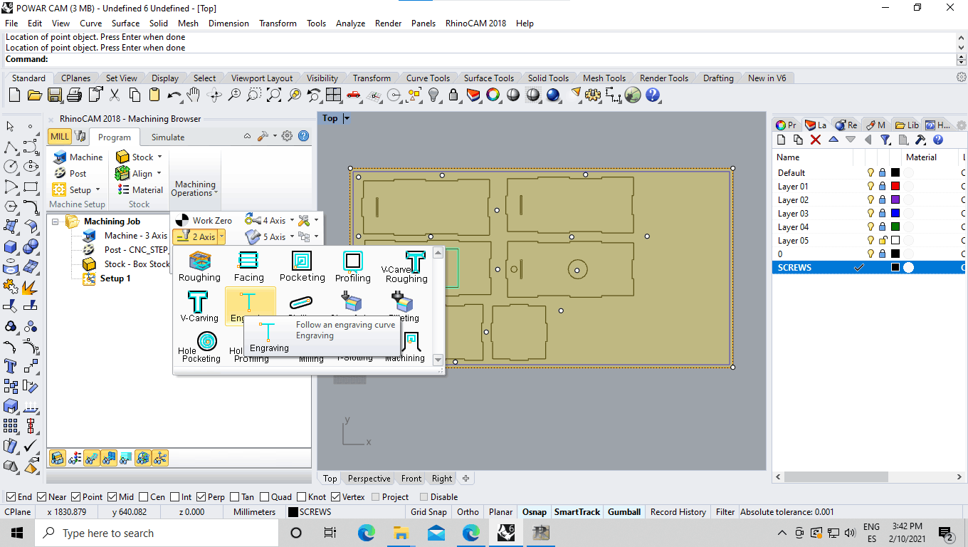
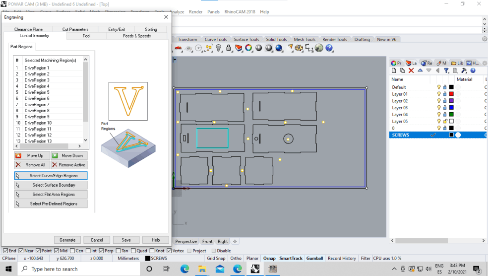
  • ***TO CREATE THE SCREWS*** 
  •    1.  OFFSET:
            a. Select the outer part of the image.
            b. Create an offset of 20mm to the inside.
            c. COMMAND > offset > 20 > ENTER 
            d. A Yellow line will appear.
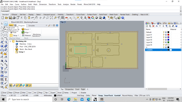
  • 2.    POINT CREATION:
            a. First create a layer called screws.
            b. The screws will  be painted like dots because the material is not attached.
            c. Check twice that you are working in the screws layer.
            d. The point 0,0,0 usually is pretty worn in the CNC bed because everyone uses it... (DON'T USE IT TO ADD SCREWS)
            e. With ENTER you finalize the action.
  • 3. MACHINE OPERATIONS:
            a. Select "2 axis".
  • With 2.5D, the machine will move X and Y and then Z, not the 3 at the time.
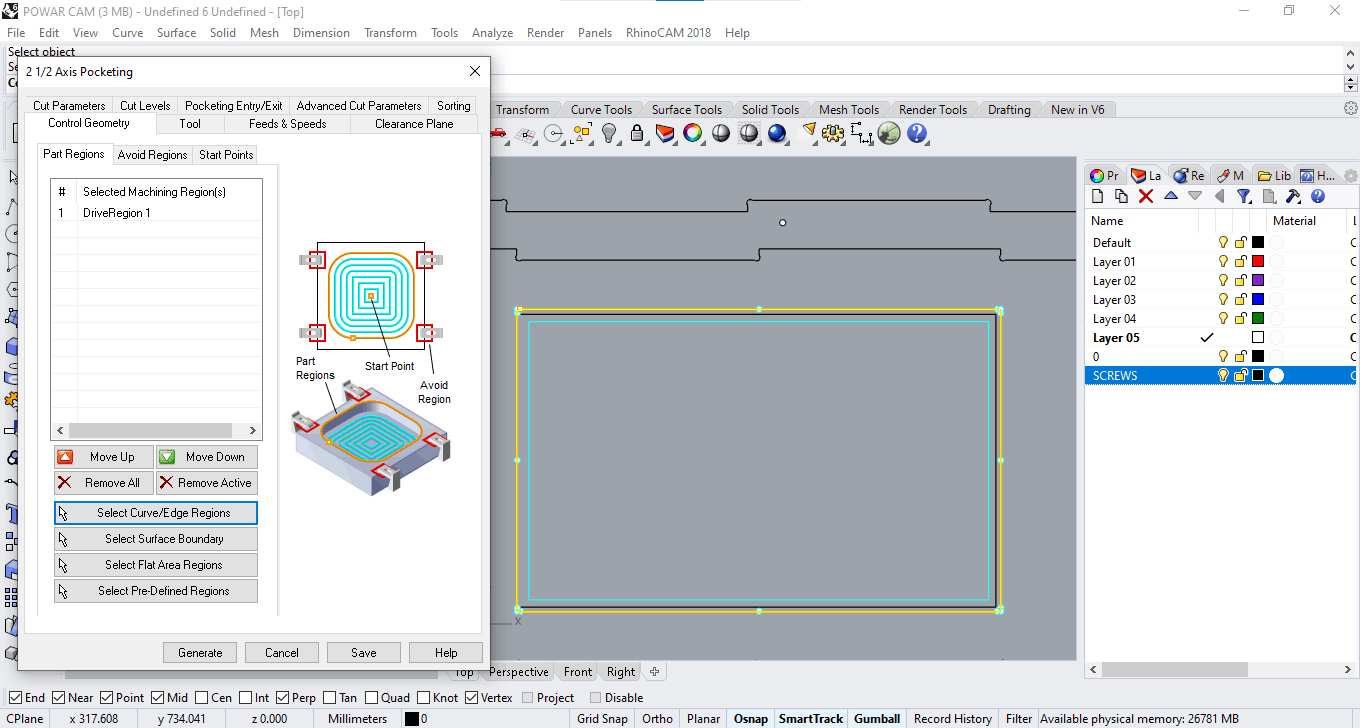
CONTROL GEOMETRY:

1 Press: "select curves or edge regions".
2 -
Choose the geometries you want to cut from the file preview.
3 -
Select the Screws Layer in the right.
4 -
Select all screws.
5 -
SAVE
Mobirise

Spindle RPM, feed rate, chip rate:

All of this values come from an equation that depends on some variables, that come from the tool, the machine and the material. I took the following information from a Spindle brand webpage: PDS SPINDLE

I copied it here because they explain very well how does these combination works better for a good balance, and to share the table of chip rate. After their definitions, I will explain how I got mine.

https://www.pdsspindeln.de/en/application-data/speed-feeds

Spindle RPM and Feed Rate Calculations:

A precondition to obtain maximum machine performance, tool life and chipping efficiency is to balance the optimum chip removal, cutting speed and feed rate of a machine. The following article provides valuable information on how to maximize the machining performance.

Spindle speed

Incorrect spindle speed is a common error in CNC machining. Each material and kind of machining requires an ideal tool profile and cutting speed. Larger tool diameters require slower cutting speeds. It is important to align spindle speed and feed rate for any given machining task to achieve the maximum quality, tool life and service life of the spindle. The spindle speed is hereby controlled by a frequency converter. All spindles are 3-phase asynchronous motors with an infinitely adjustable speed from 0 rpm to the maximum nominal speed.

Feed rate

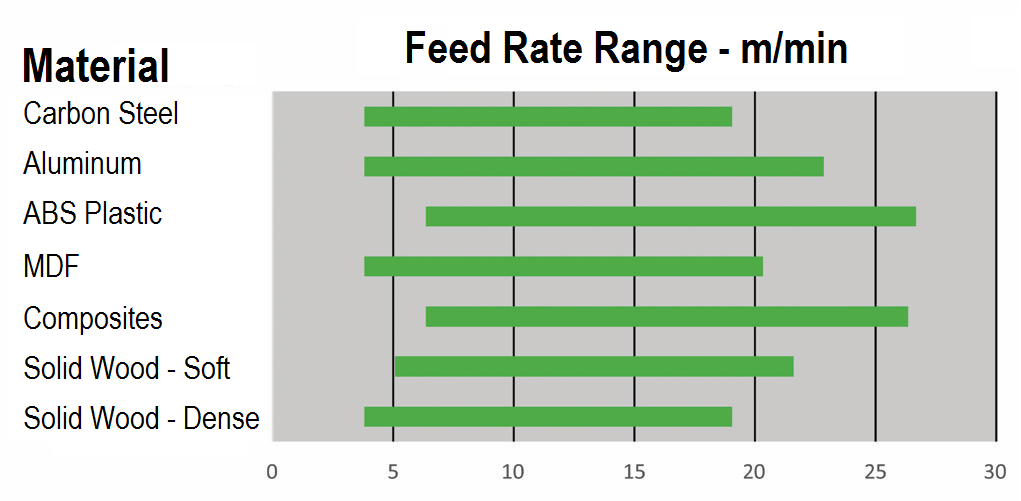
The feed rate of the cutting tool must be balanced proportionately to the spindle speed. Changing one factor influences the other factors. A too slowly set feed rate reduces the tool life of the cutting tool and might cause overheating and thus result in burn marks on the work piece. As a result, not enough material is removed and the cutting point is insufficiently cooled. The feed rate chart below provides information on starting point values. We recommend setting the specified mean values for the first start-up. Contact your cutting tool supplier for individual advice for your specific application.

Mobirise

Chip Rate

The chip load is a term used to describe the thickness of a chip removed perpendicular to the cutting direction, measured vertically to the cutting direction. The chip load is sometimes also referred to as "feed per tooth" and is calculated as follows:

Mobirise

The chip load is one of many factors used to determine spindle size and machine parameters, such as:

    -    Speed range and the power requirement for the spindle
    -    Determination of tool load depending on cutting tool model
    -    Calculation of torque for available application

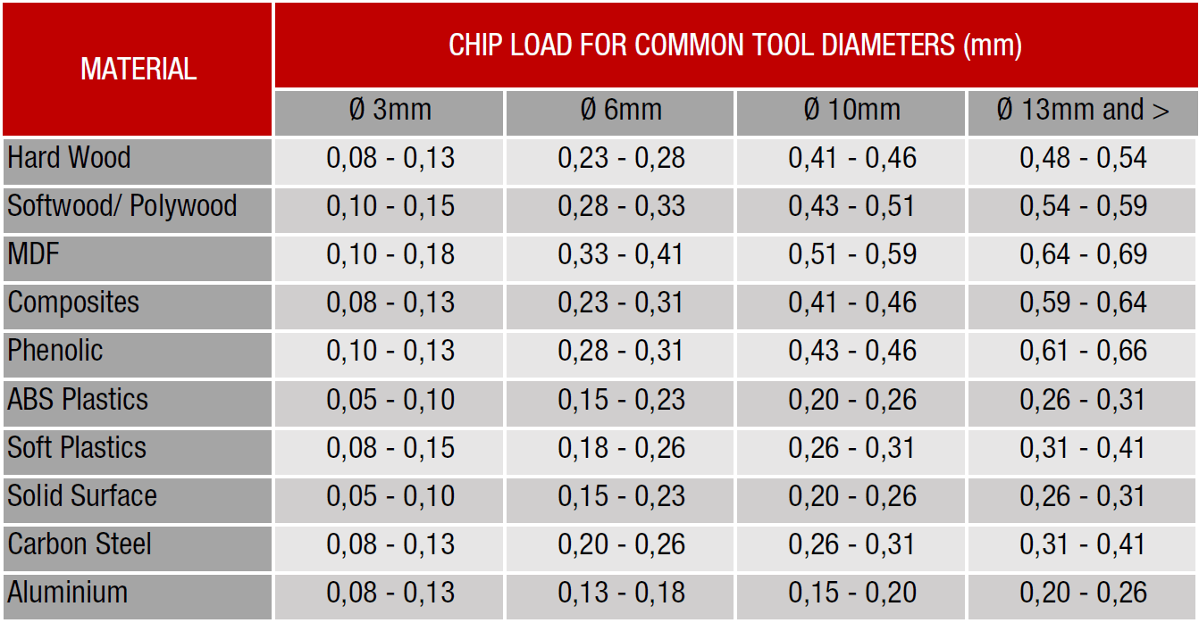
We recommend contacting a PDS applications technician in case of new spindle applications to support you in establishing the baseline cutting values. Our employees will be glad to answer your technical questions on the phone or by email. The chart below provides information on chip loads for common milling tools. These are “not to exceed” starting values for first time setups. Actual values may vary as a result of various machine factors, of course. These factors include: rigidity, power, tool clamping, spindle fixing, work piece clamping, and others.

Mobirise

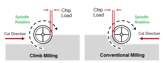
The chip load is an important factor to determine the cutting speed and the feed rate. As far as wood is concerned, a chip load that is too low causes too much heat on the cutting point. The “dust-like” chips may cause burn marks on the surface in turn. A chip load that is too high is pushing the cutter through the material causing too much pressure. The high radial loads on the spindle bearing resulting from that can cause spindle failure, excessive tool wear, and tool break over time. As far as milling is concerned, there are generally two kinds of milling: synchronous milling and conventional milling. For wood working, synchronous milling produces a better milling quality as the generated chips are torn out to a lesser extent. Synchronous milling should be preferred as loads are lower and tool life is longer.

Mobirise

MY SETINGS:

This are the settings I used, keeping in mind the equation, the material and the tool to create my tool on the software. measured with a caliper the tool to get some info from it.

Tool diameter:     6mm.

Material:               Plywood: 0.28 - 0.33

LOWEST:                18000 (RPM) * 1 (flute) * 0.28 (chip load) = 5040
HIGHEST:               18000 (RPM) * 1 (flute) * 0.33 (chip load) = 5940

*FEED RATE should be more than 7000

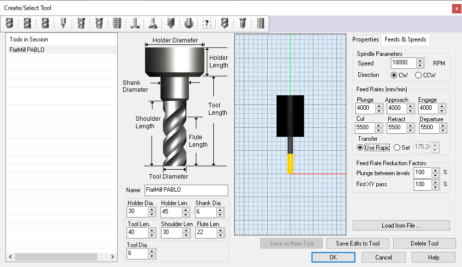
TOOL:

Press: Create / Select tool

1 - TOOL always turns right.
2 - HOLDERS: Is the piece inside the machine holding the drill. The values are taken from the machine.
3 - TOOL LENGHT is the part of the tool that is outside the holder.
4 - SHOULDER y FLUTE the part that cuts from the tool.
Mobirise

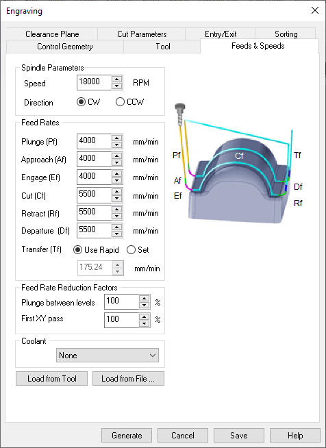
PROPERTIES: Feeds & Speeds

Spindle Rate, and CUT
Use Feed rate calculation.

Plunge, approach, engage:
This is the speed at which the tool enters the material, it should be more or less, half of the CUT.

TRANSFER:
This the speed of movement in air. We always use USE RAPID, but we set the value to 10000 for simulation.

DIRECTION:
CW (clockwise) do not change, depends on the machine.

FEEDS AND SPEEDS

This is the same tab that we have seen before.

(LOAD TOOL)
Mobirise
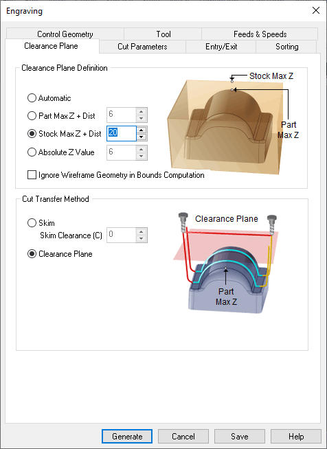
CLEARANCE PLAIN:

This is the flight speed when you are not cutting, so you don't hit anything.

CLEARANCE PLAIN DEFINITION:
Stock max z + distance (20mm).
CUT TRANSFER METHOD:
- clearance plane.
Mobirise
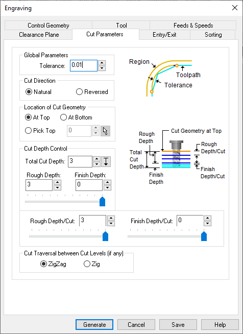
CUT PARAMETERS:

Tolerance:
0.01 (lower the value, it is more exact)

Cut Direction:
Natural

Location of Cut Geometry:
At top.

Cut depth tool:
3mm approx for screws.

Rough and Finish:
This is a configuration where you decide if you want the first ones to be ROUGH and the last layers more detailed… in this case everything is rough.
Mobirise
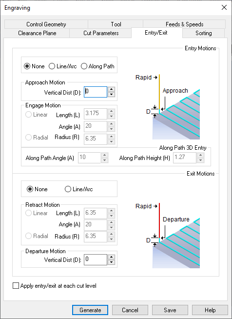
ENTRY EXIT:

It's the way you enter the material: Enter straight and first cut, or enter cutting as in 3D ... (parabola).

At the moment we leave NONE in the two options because we want it to go straight.
Mobirise
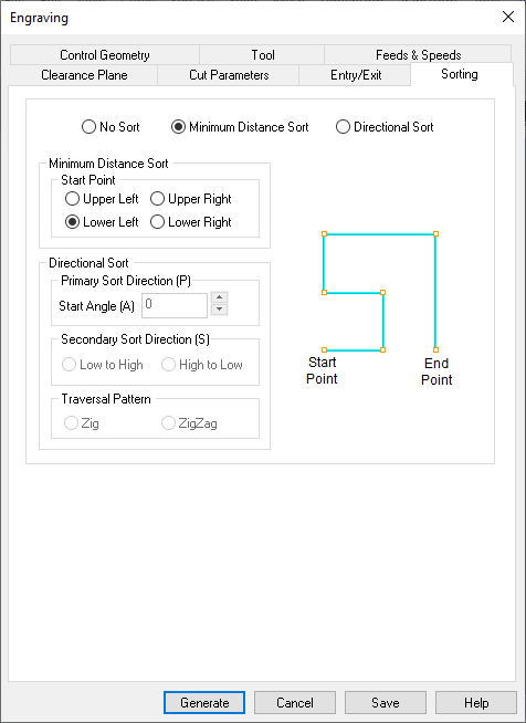
SORTING:

The way you organize your cuts, to take as little time as possible. (minimum distance sort)
Mobirise

POCKETING SETTINGS:

After I created the settings for the engraving of the holes, now I'm going to duplicate the settings file and modify some settings for the pocketing.

Mobirise
Mobirise
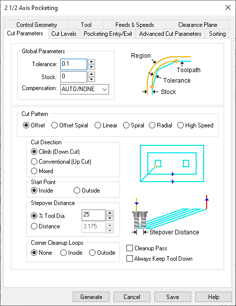
CUT PARAMETERS:

GLOBAL PARAMETERS:

Tolerance I leave it the same.
The Stock I lower it to 0 (it's the offset distance between the lines and the tool)

CUT PATTERN:
The way you remove the material (from the inside, linear, zigzag, etc) OFFSET works very well.

CUT DIRECTION:
Climb
(because the tool is downcut)

START POINT:
Whether it starts from inside or outside the line.

STEPOVER DISTANCE:
How much the tool is mounted on the previous cut (how much percentage of material it eats in each cut). Overlapping.

CORNER CLEANUP:
In case you want me to clean the corners. Not in this case.
Mobirise
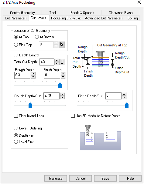
CUT LEVELS:

Total Cut depth:
5mm which is the size of my acrylic.

ROUGHT DEPTH CUT:
How much it cuts in each cut. The maximum can be 3mm (half the diameter of the tool)… let's give it 2.5, which is half the depth we want.

CUT LEVEL ORDERING:
DEPTH.F: cut one piece first and then the other.
LEVEL.F: cut by levels in all the pieces at the same time.
Mobirise

Small parts Pocketing and Profiling:

For small internal parts, it is better to do a potting again, so that all the material is eaten and not having to make bridges.

Everything is configured completely the same, except the CUT DEPTH to which I give the width of the material, plus a little more (0.3, 0.4, 0.2 ...) 9.3 in this case (material 9).

Now we continue with PROFILING to do the INNER CUTS, so we generate another configuration and chage some settings.

PROFILING: IF something is selected, he chooses it for me from the start, it is better to remove everything and start over.

CUT PARAMETERS:
- GLOBAL PARAMETERS: Tolerance 0.01
- CUT START SIDE: Here I choose if I want it to cut inside or outside.

ADVANCED:
(We make the bridges here.)

BRIDGE / TABS: Rectangular. 4x4mm is a good measure. One is the length of the bridge and the other is the height it leaves above the surface.

NUMBER OF BRIDGES: This applies for each piece selected.

Saving G-Codes:

- Select strategy (operation / folder / layer)

- Right click, and post. And it opens me to keep it, I choose the place.

- Declare the machine: CNC_STEP_BCN (or the on of your chooise)

- I first create a file only for the SCREWS, since I'm going to have to screw the wood to the bed after.

- Since the other strategies can be done continuous because they use the same end mill, I choose them all and there I clic on "post".

IF you change end mill, you must make a different file.


LINK TO FILES:

Machining with RaptorX-SL:

We used the Raptor X-SL 3200/S20 machine and its software KinetiC-NC to do the test. The detailed specs of the machine:

Working area: 3,200 x 2,010 x 300mm
Clamping area: X -3,500mm x Y -2,200mm
Positioning speed X+Y/Z: maximum 40,000mm/min
Working speed: maximum 20,000mm/min
Step width X: 0.0213mm
Step width Y+Z: 0.0113mm

Mobirise
ESP8266 12-E Chip Pinout

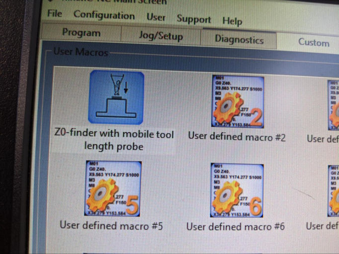
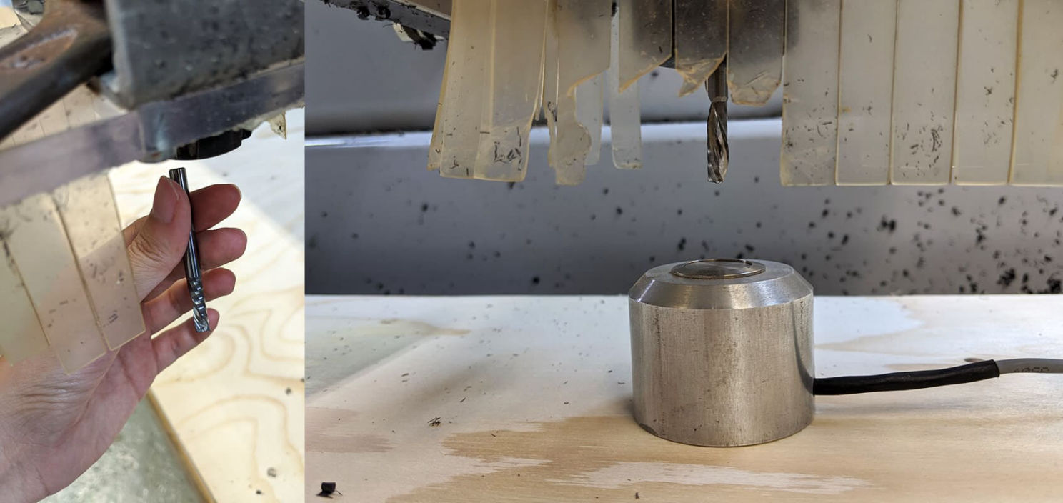
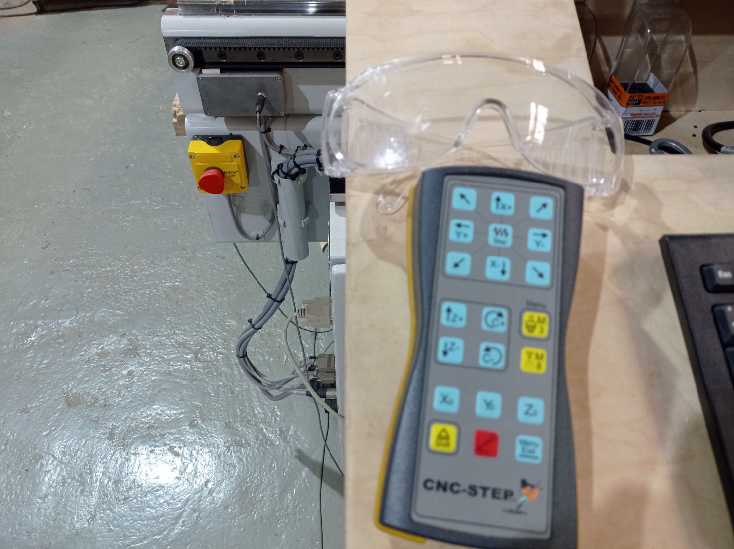
The first step you should always do, is to calibrate the X, Y and Z (0, 0, 0) of the machine. For this we are going to use the control panel of the software, the length probe and the control pad.

First we set the X and Y to the 0,0 point. We can do this in the panel or with the external control.

Then we are going to move the X and Y to a place where we can calibrate the Z, it is recommended not to do it in the corner, because sometimes this place is lifted a bit.

We put the length probe right under the end mill (it is very important to be sure it is right under it) and then we run the "Z0-finder with mobile tool length probe" script in the software. This will make the Z axis to lower down until it reached the probe, and it will automatically set the Z axis.
Safety Advices:

The CNC is one of the most dangerous machines in the lab, because it can Kill You! This doesn't means you should be afraid of it, but it means you should follow always two safety recommendations:

Mobirise
ESP8266 12-E Chip Pinout

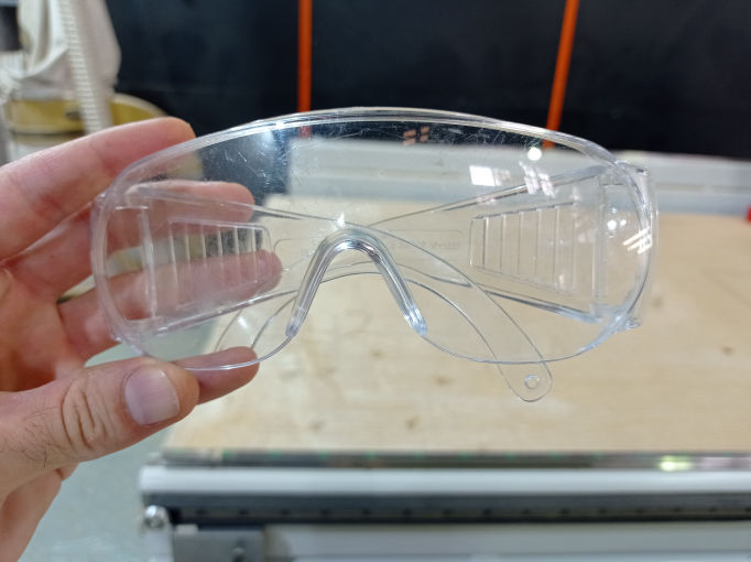
Wear Safety Glasses!

CNC is like a gigantic drill moving pretty fast, scrapping some material with a metallic end mill, and therefore, it could make some material splinters to fly towards you or in the worst case, the end mill could break at a really fast speed by hitting a screw or something else, and it could fly directly into your eyes, so it is recommended to always use safety glasses.
ESP8266 12-E Chip Pinout

Never leave the machine alone!

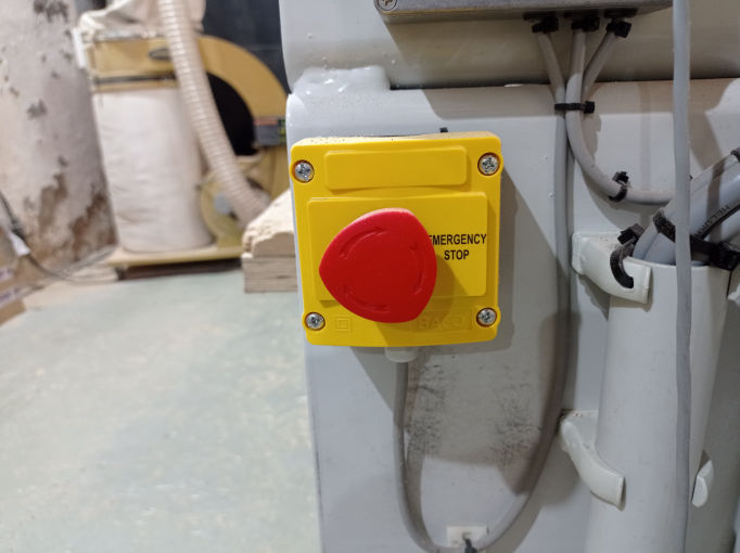
The CNC is a really strong (and expensive) machine, and therefore dangerous. Something could go wrong, like the broken end mill we where talking about, or someones shirt could get trapped in the chains of the gantry and pull him, or it should hit someone really fast. That's why you should always keep an eye on it(with safety glasses on as we said) and stand in front of the emergency stop button so you can quickly stop it in case anything goes wrong. This CNC has two emergency's button's, in opposite corners, one of them close to where we turn it on and control it (X-0,Y-0).
Mobirise
Voltio

Page was started with Mobirise