Final Project General Design and Hardware development
The documentation about the Monolith is divided between the hardware and the software because even if they are interconected I separate the files because they are too long
First iterations
This project has been through several iterations so I’ll number them to keep clear which state is each one.
This week I worked on defining my final project idea and started to getting used to the documentation process.
Version 01 Story in a cube
Last Wednesday I saw in the presentation with Neil a final project of someone in Mexico that was a child story told by a box with a bulb. She talked about the struggles of designing the characters and focusing in the target of children.
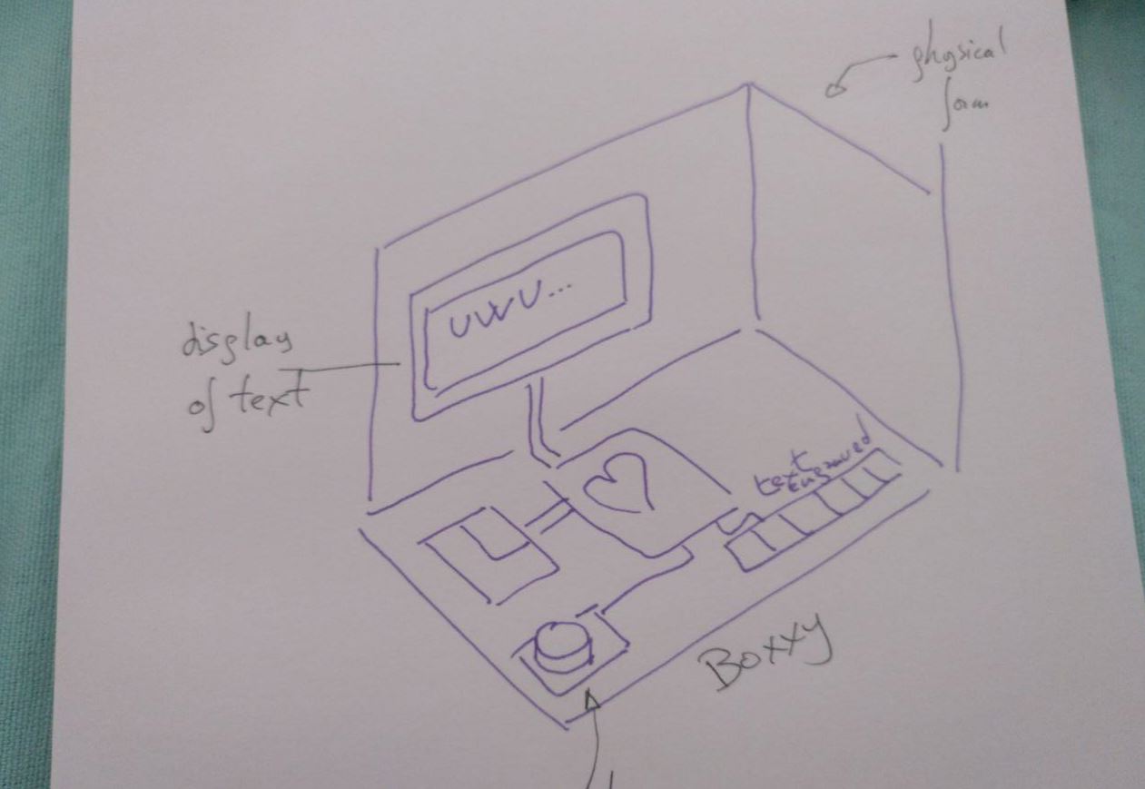
Then I wonder, what if the box is the character? And then I started drawing and drafting ideas.
References
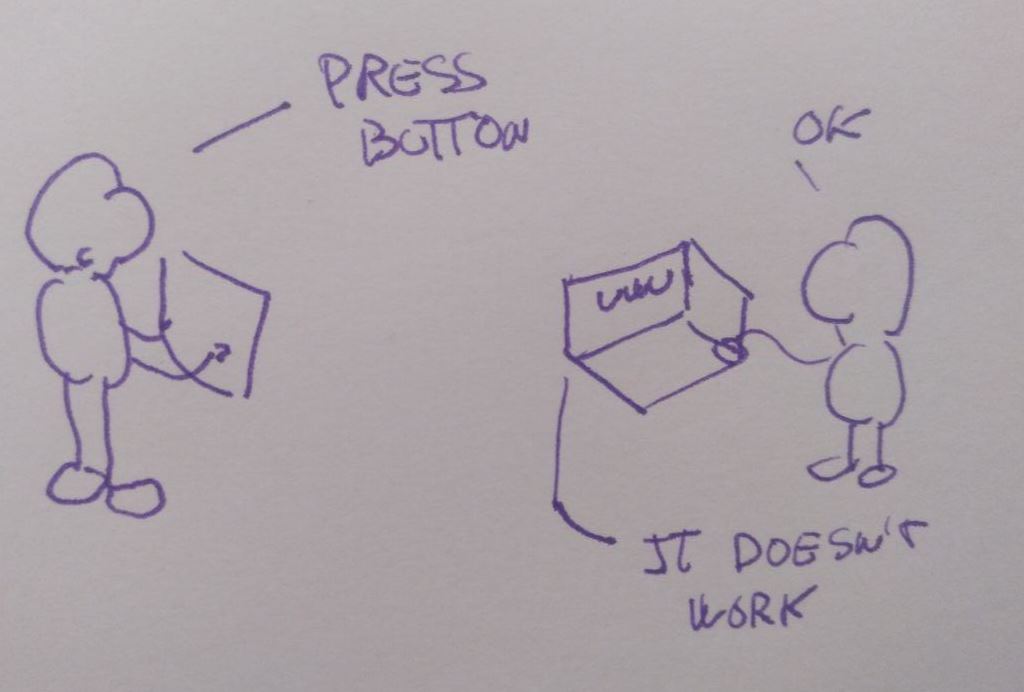
I’m not sure if this project it’s a narrative or a ludic experience. As a reference (where to hang) I think of the game “Keep talking and nobody explodes ” where 2 teams of n players have to defuse a random generated virtual bomb. One of the teams has access to the bomb and can defuse it by cutting wires and pressing buttons. The other team has only access to the instructions of how to defuse the bomb. It’s a middle ground between the videogames and boardgames.

Going beyond the bomb
I like the interaction that it’s gather in that game but I want to be more concrete about telling a story. In Keep Talking and nobody explodes the story that’s told it’s about team effort of undestanding complex instructions and some kind of race of how the team performs better each team it’s done.
I’d like instead to tell a story about the box and their feelings. I don’t know if there is a second box or instructions for another person to read. Probably I’ll play that the instructions and the goal of those instructions are not what are supposed to be. Probably if the box has thoughts about what you’re doing with them.
Drafts in images
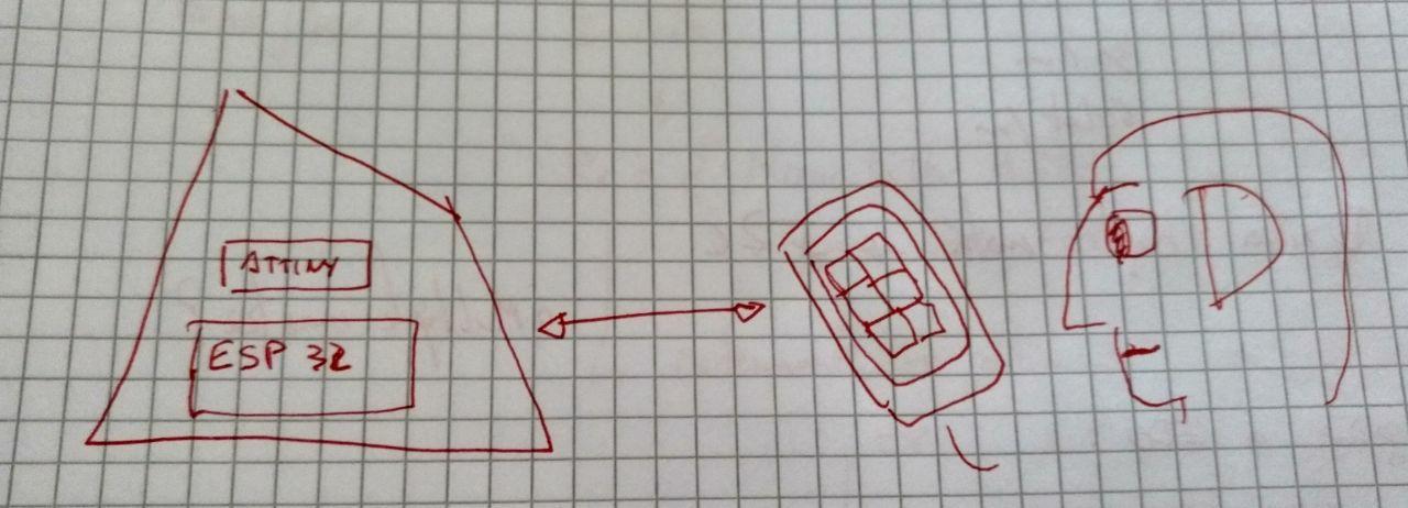
Version 02 The allien
Nowadays I’m thinking that the “box” is an alien artifact that you have to decipher and interact with. You don’t know how much is it alive or conciuos. So I’m thinking of a box that your “computer” has to interact with and it has inside the speakers or the leds.
Another reference for this is the film Arrival.
Version 03 The Monolithk and the scale model
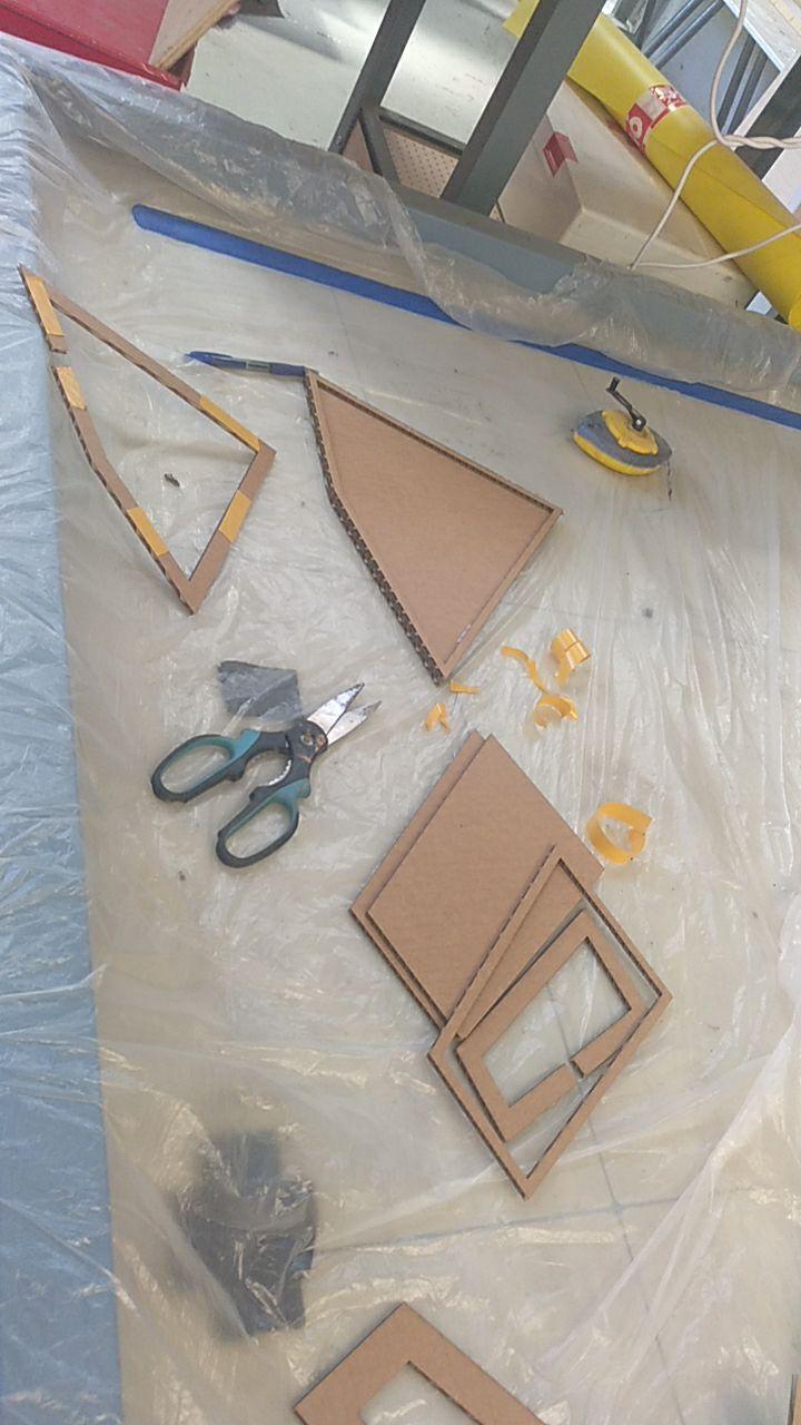
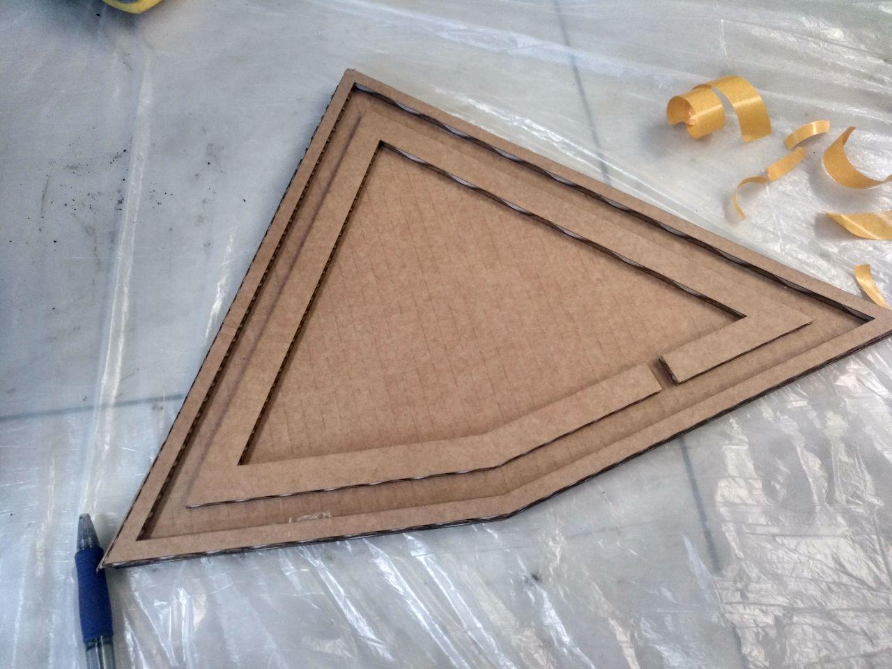
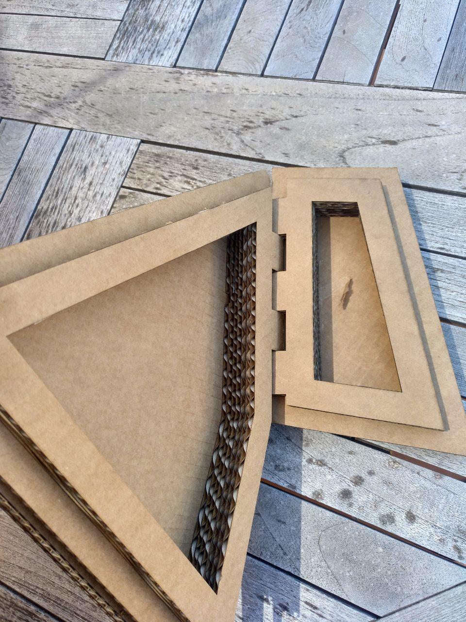
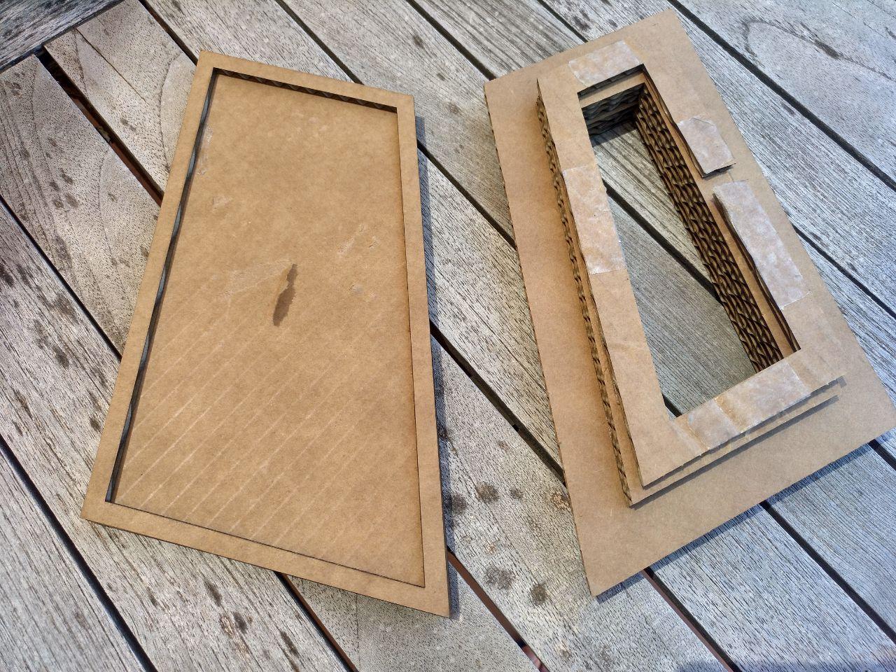
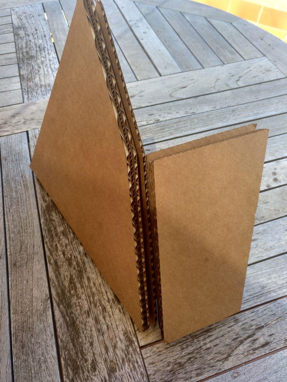
Yesteday I made a 1:1 scale model with cardboard
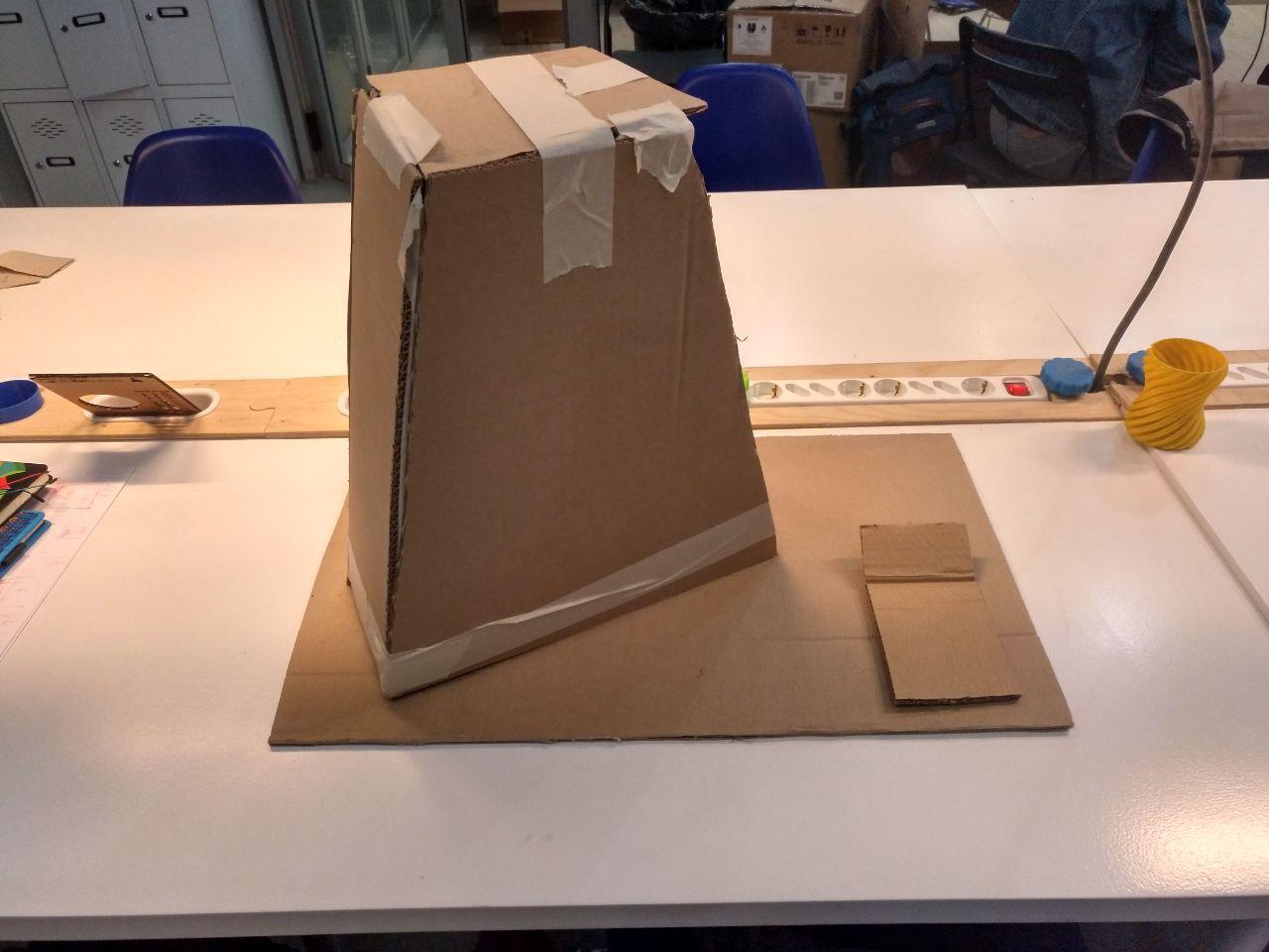 at least I can touch how big it’s going to be
And I mapped the project into the next weeks
-
Make something big: Iteration over the Monolith
-
Inputs: Make the buttons and display
-
Outputs: Make a circuit to control the outputs.
-
Network: Work with the comunication between the input (master) and output (slave)
-
Molding and casting: Try to make some parts of the Monolith soft and breathable (I have to look for softrobotics)
Trying to make something big and discussion about how is the Monolith
I commented the project with my instructors and there were some things to be.
I think that the idea of the game is that you get familiarized with the Monolith that at first glance seems to be inorganic but with the interaction you will learn that’s alive. That gives me an idea that how alive it feels has to change with the course of the game.
In the tutorial and in the
The story and main loop
The main loop for this is going to be an idle state, that goes to a tutorial (through a password that the instructions give you), a main part of the game and the decision part of the game. You can go back to a idle state through a password (given by the instructions)
The tutorial in the story is a series of instructions that will ensure that the person with the object and the person with the instructions can comunicate together.
The assessment
Here is the assesment so how can I fullfil this with this kind of project:
- Create your own integrated design
I should make some experiments of how it’s this box and how is they. Boxxy is the preliminar name.
- Demonstrate 2D & 3D modelling capabilities applied to your own designs
I need to shape Boxxy and that will need my 2D and 3D capabilities.
- Select and apply appropriate additive and subtractive techniques
I guess that substractive techniques can work for the structure of Boxxy and additive (casting shapes of buttons) can work for inputs or little designs
- Demonstrate competence in design, fabrication and programming of your own fabbed microcontroller PCB, including an input & output device
I don’t know if I can make the microcontroller as complex as I want it to be, but there will be an outpud of a display and inputs in several ways (at first buttons)
The Monolith demo game in Twine
To try to test how the final project it’s going to behave I’m doing the project with twine to have a routemap of what to do.
Twine is a open source platform to make text adventures with a nice gui and documentation.
The base is javascript with some specific formating (not markdown). When you have your adventure you produce
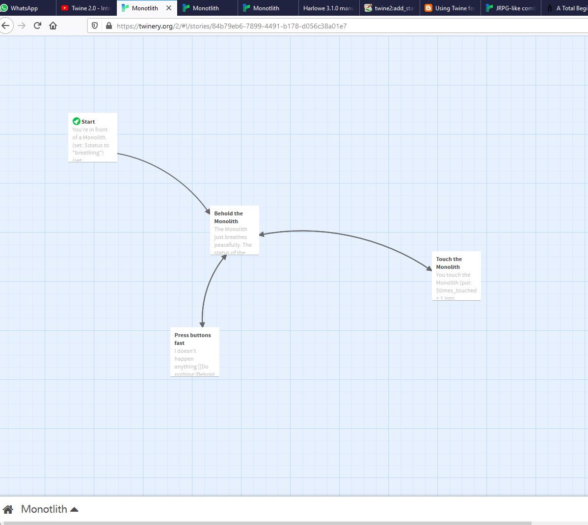 this is where you plan your scheme
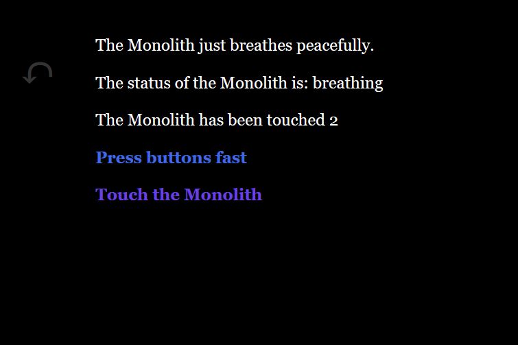 this is how it looks (by default)
For now I produce the first steps of what I planning to do and some wishlist.
I’ve used this software before, but this is the first time that I’m trying to use variables on it so when I put this code into a python or a C++ code in the ESP32 it will be easy for me.
Now I dream of making the Monolith a different random individual with different “stats” once you plug in but that’s too far in the future.
Here you can see the first draft I’ve made
List of sensors by now
-Doppler radar for barduino (this is like the proximity sensor). Only give you high and low.
-Capacitivy sensors. Like 4-5 zones to touch.
-Button display with symbols that are difficult to read.
List of Outputs
-
4-5 sheets of leds (different parts of the Monolith). (dot star?/neo pixel?/normal ones?)(use fastled library?)
-
Buzzer for “subtle sounds”
-
Alarm for alarm sound.
-
Vibratory motors.
-
Display.
-
Pumps for soft robotics valves hydraulics? how much does it sound? can it be used also as sound of the Monolith?
The schema of the Boards is Like
Main ESP32 that talks with the display and has the loop.
Slave ESP32 that process the “moods” of the Monolith and the recieved.
Other boards for maybe the motors or sensors that needed?
04 The Monolith design
I’d like to prototype more using the laser cut machine but since it’s not posible because I can’t access the lab, I only can try to draw it and iterate that design without the physical counterpart.
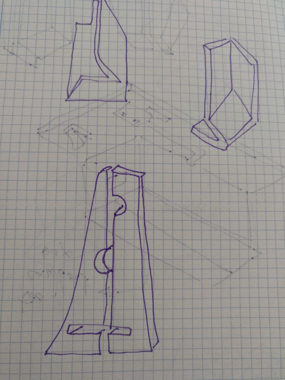
In this case the core idea it’s that the players are going to learn that this is alive during the game and not vice-versa. So the inspiration are more abstract sculture instead of living moving organisms. If I can I would like to add some of that “soft-robotics” thing but I guess that is a stretchgoal rather than the nucleus of the project.
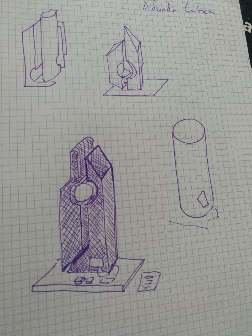
In this case I’m using a irregular heptagon (7 faces polygon) so it’s near something known but not likely. There is a tiny square base. (this is all drawn in procreate)
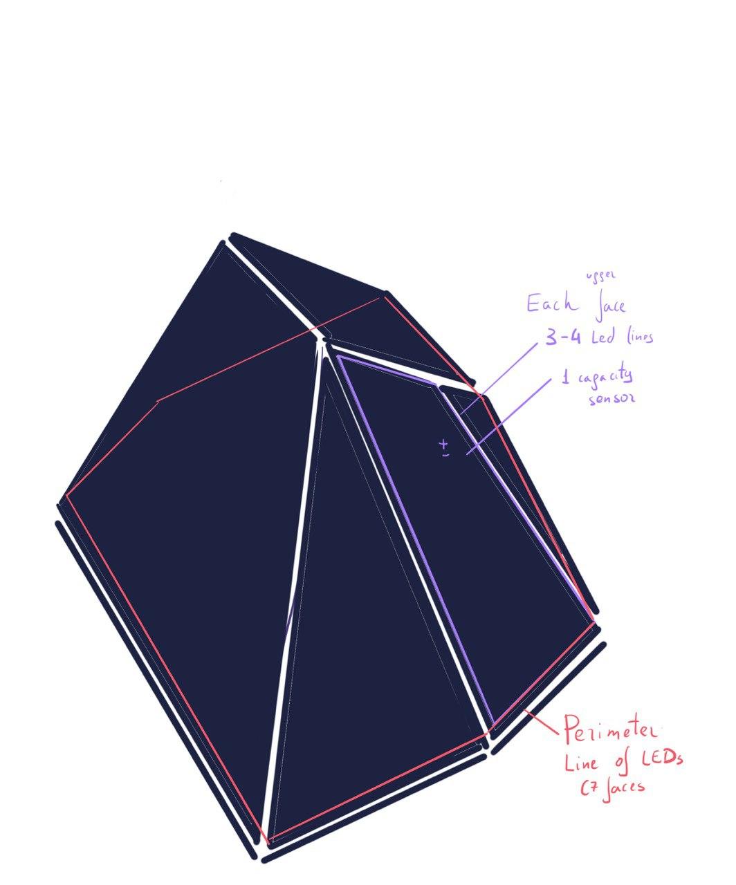
This is a draft of the exterior look
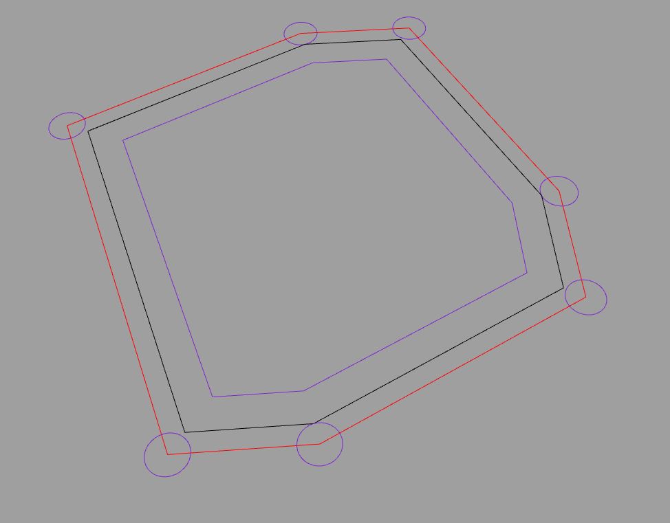
This is the structure schema. Since it’s going to be 80 centimeters tall I need some internal skeleton to hold everything and make wire it properly.
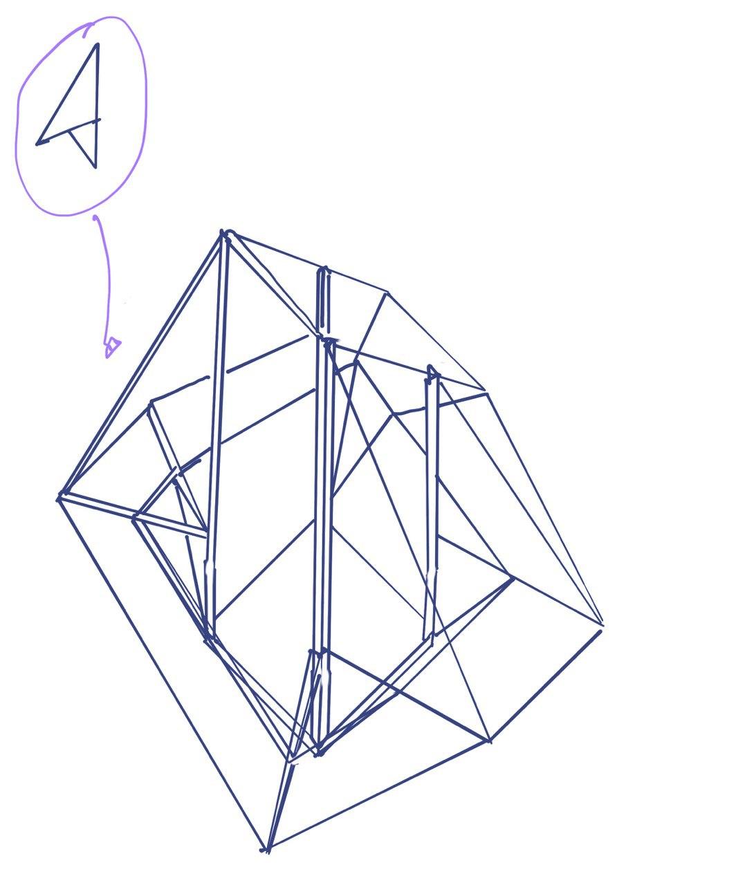
Structure schema
The idea it’s that there are 4 pillars that they hold all the 7 “faces”of the Monolith so they hold together. They are also joined by 2 rings, 1 exterior ring and another interior ring that makes the Monolith apear to fly a little over.
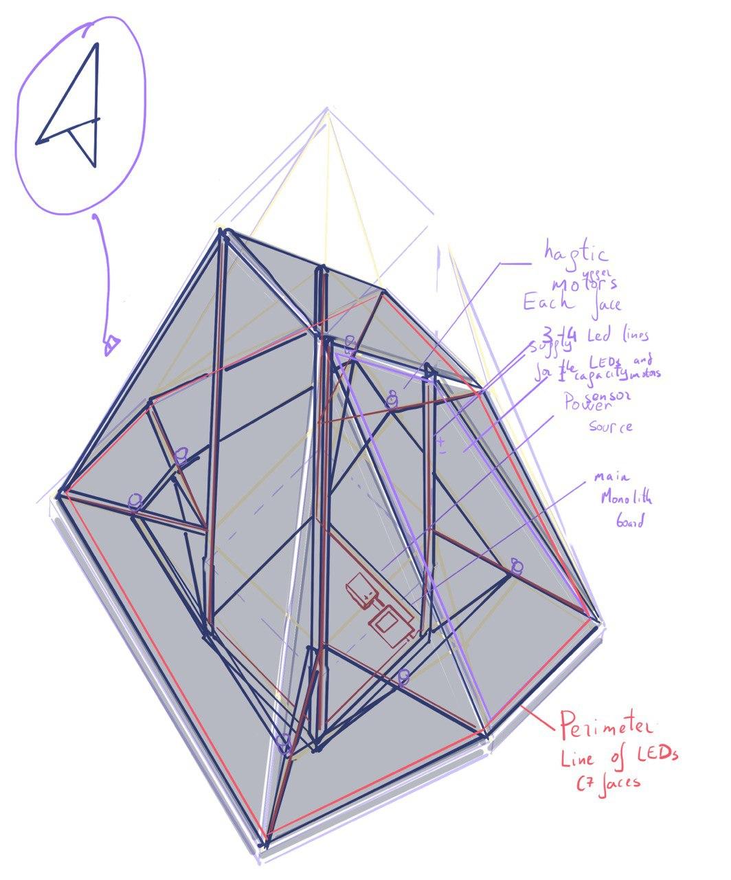
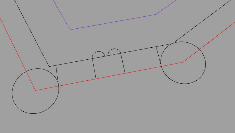
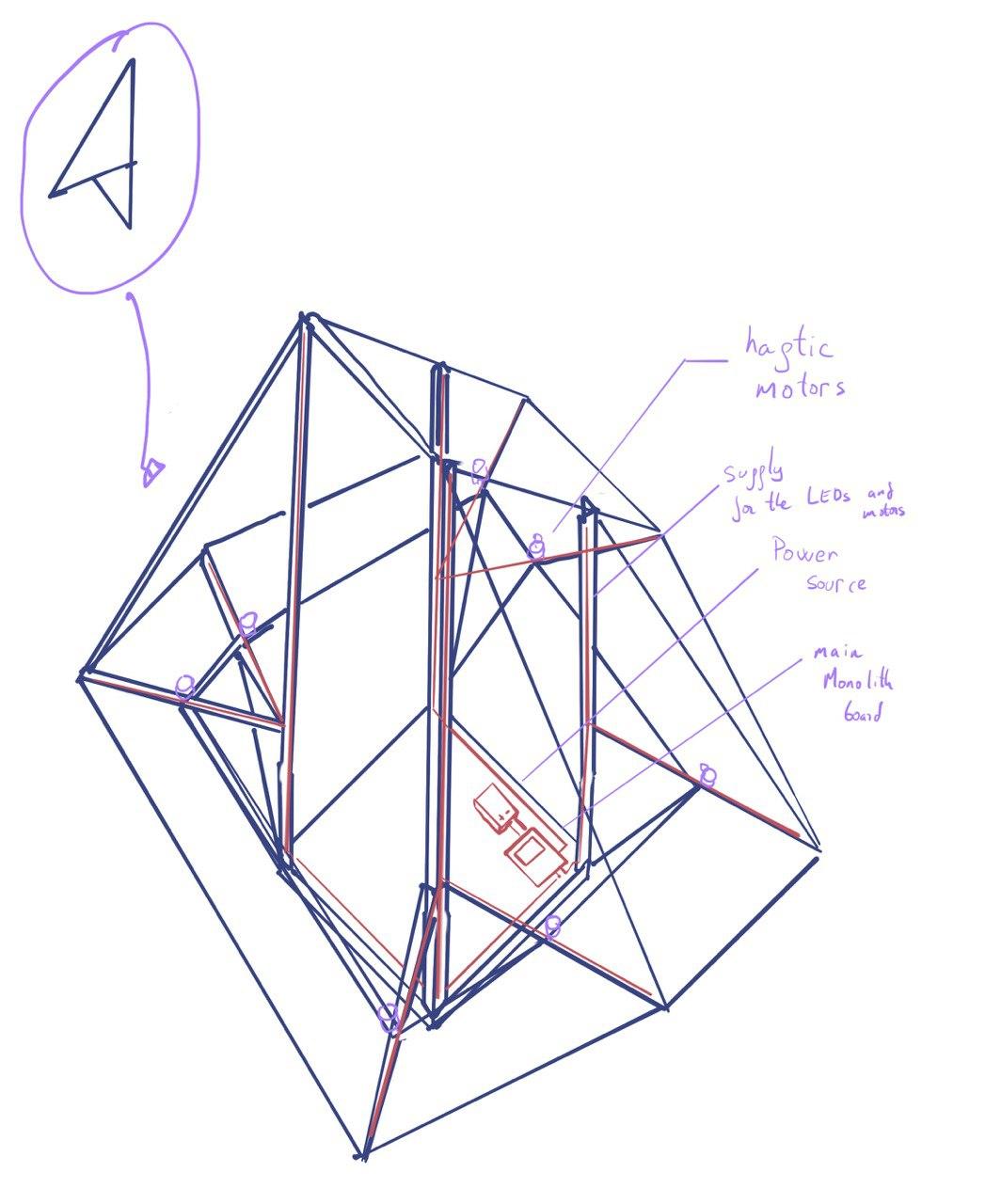 Draft of the interior things of the Monolith. Not to be seen by players
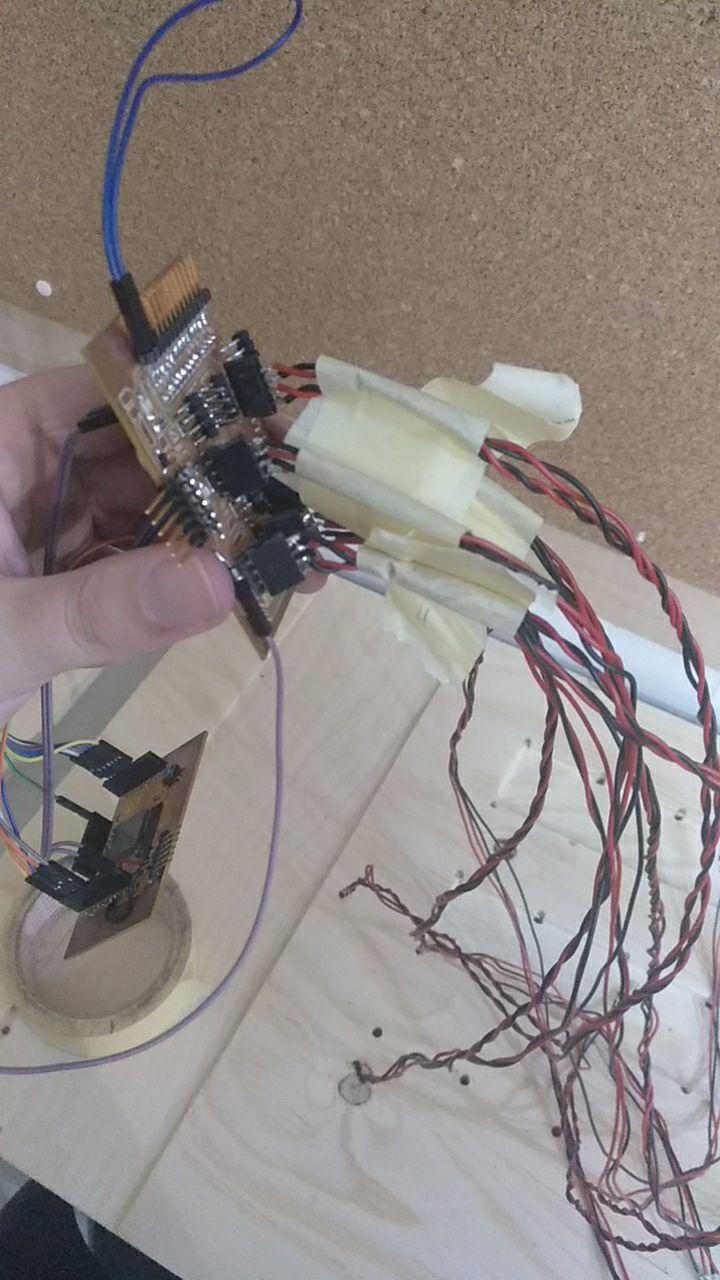
The main brain of the Monolith will be located inside in the bottom part of the structure so it can be taken out and debuged or repaired in conjunction with the powersource. The idea it’s that the wires that go to that main board are numbered and they have any kind of connection yet to be determined.
Now I have doubts. Since I will have at least 7 input output sensor (with leds) should I control all of them via pins of the main board or should I use more tiny microcontrollers boards that handle each of them only a face of the seven and communicate with the main board?
The other thing I have to design further is the join detail so I can assemble everything. I need to hide the LEDS so they are not seen as leds but points or lines. I could use the wire but it’s not durable.
From the lockdown to the design.
Finally I could ask for the lab for material to keep prototiping now more focused in go step by step in the way to go the final project because I need to things to sort out.
So I started to use trello to divide and conquer
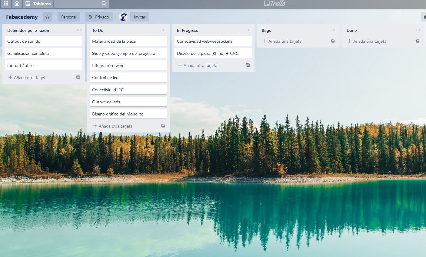
just to not forget anything and not swim in “there is lot’s of things pending”
I could figure out how to connect everything. I ditched oud the phyical pad (for now) and substitute it with a web served by the ESP32 inside the Monolith.
this is the idea of how it’s the interaction from the user
And going inside I’m going to test some websockets. I even can try it with a dev ESP32 to test if it works. I might even use the same twine I’m using!
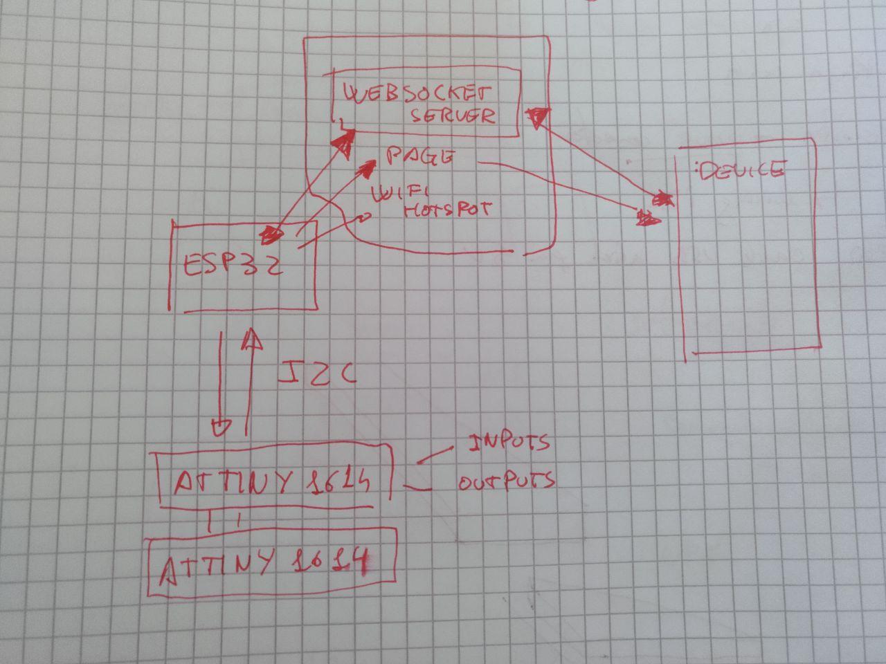
this is the idea of how it’s the interaction from the user
Starting design with grasshopper
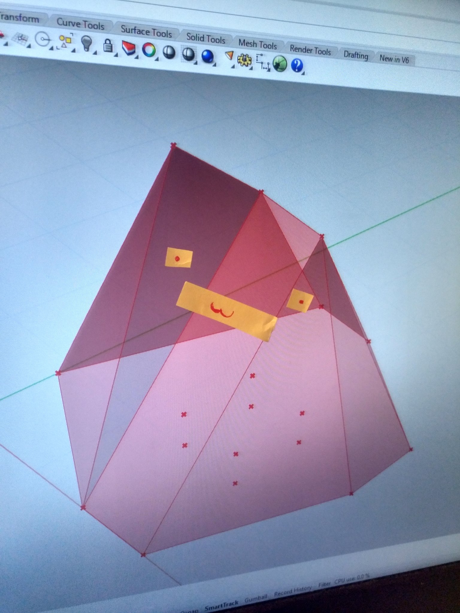
Now I’m trying to shape with grasshopper and rhino the prototype to work with it.
This is what I’ve got by now. Now I have to make the boards to be cut with cnc and add the details so 7 faces can be touchable.
The Monolith could go and say : 3
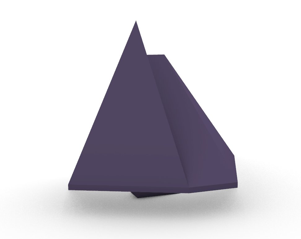
Monolith render
Here you can see it properly thanks to Sketchfab:
_
Thanks for the people on the MCU that reminded me that Sketchfab it’s a think that exists
Now I’m going to document in the 2D and CNC assigment.
Going to the CNC modelling.
Once I’ve tested the one face prototype and done the CNC assigment I feel confident enough to try to make the skeleton of the Monolith with the CNC.
When I see the project again in grasshopper I see a problem:
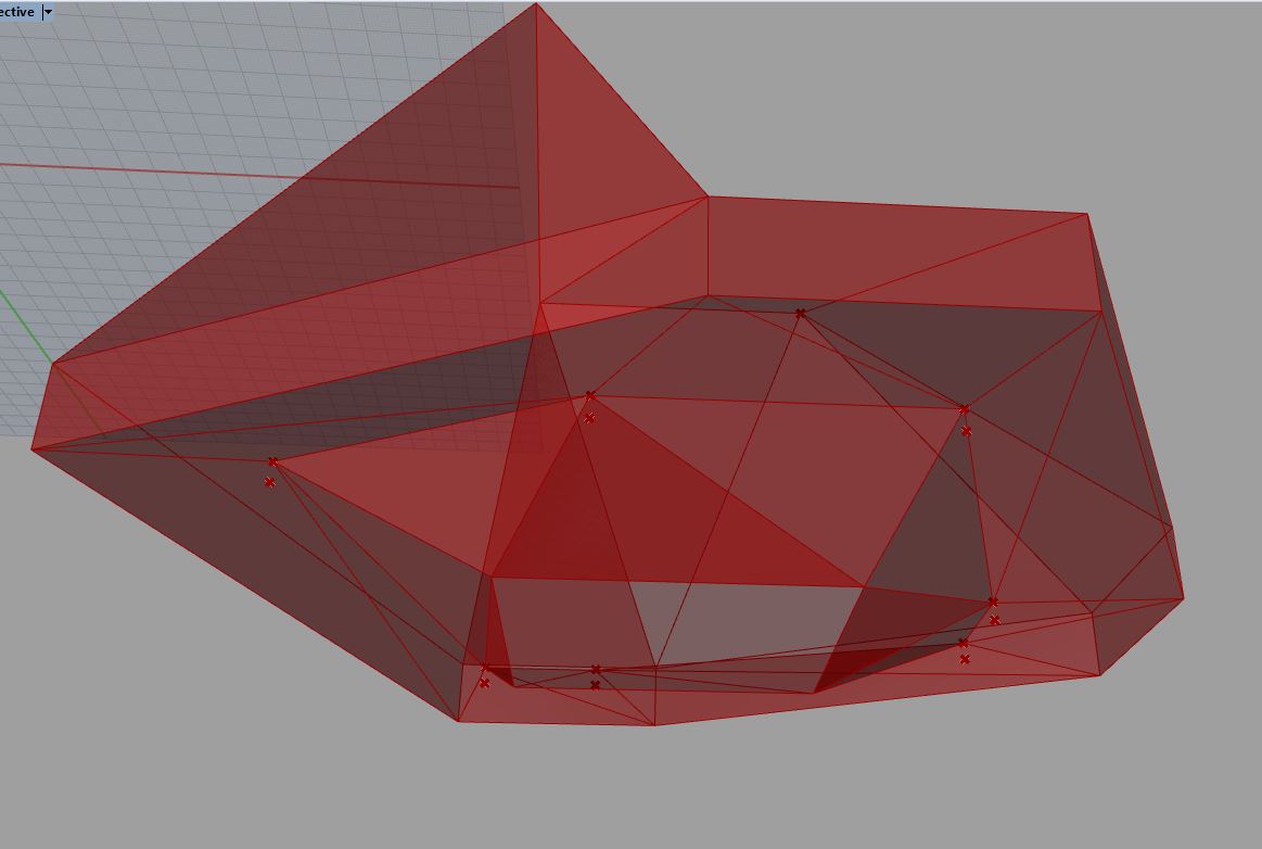
This is going to be complex as f***
And it makes do this crazy faces:
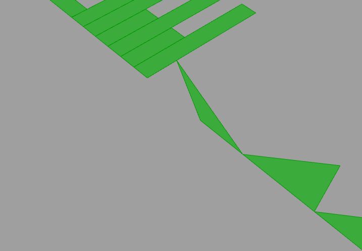
This is a no-no
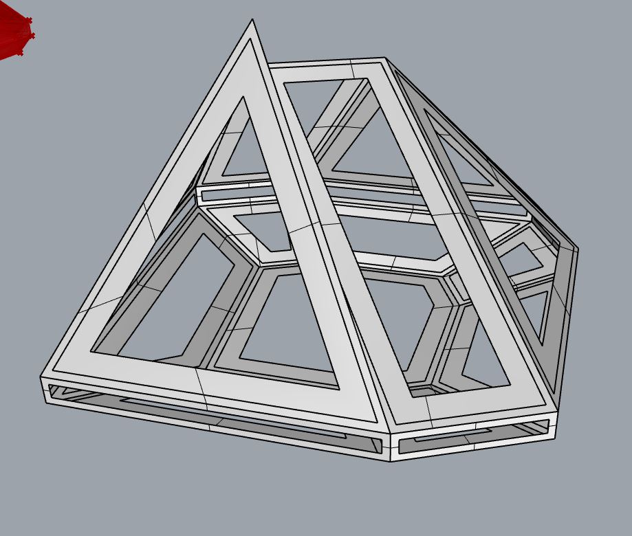
So let’s change it. For now let’s forget about the complexity of the bottom part. This is going to be the result:
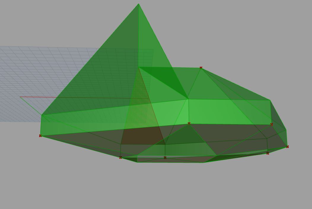
No I’m going to change the bottom square for an heptagon (the same base heptagon) to have more squared faces.
This is way better:
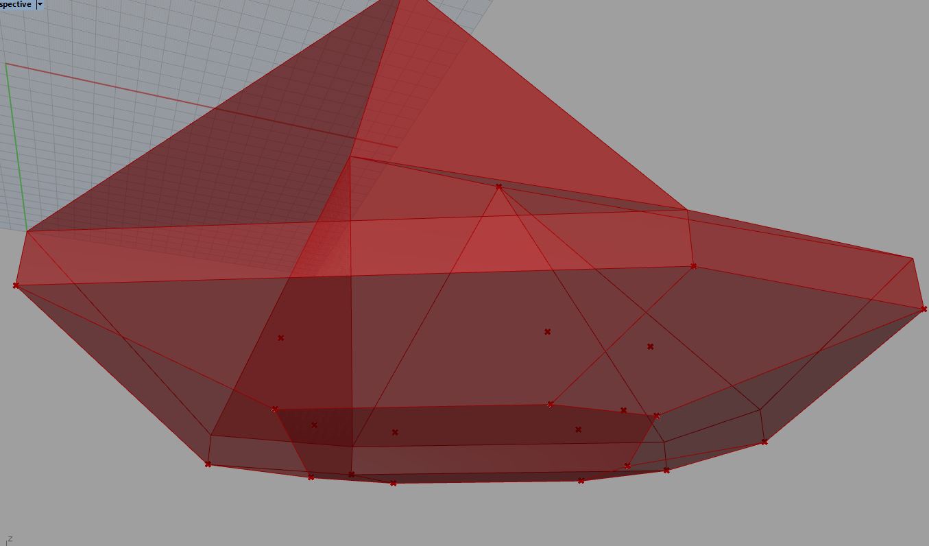
I think I can mount that!
Now I can expand those geometries like this:
The Face prototype
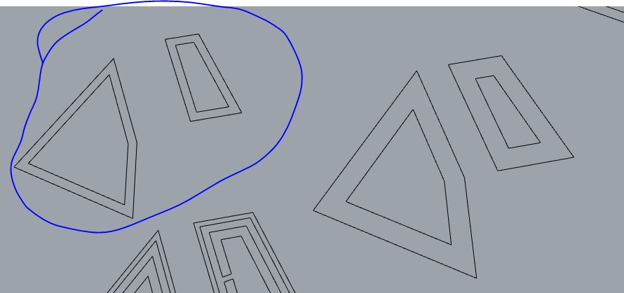
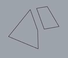
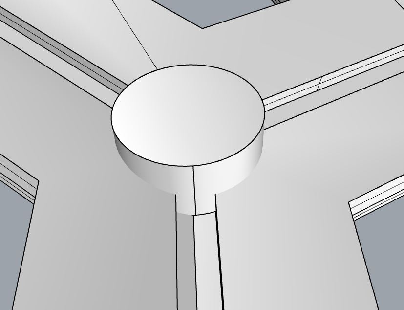
I’m using a couple of face to test out the constructive core of the Mononlith pyramidal shape.
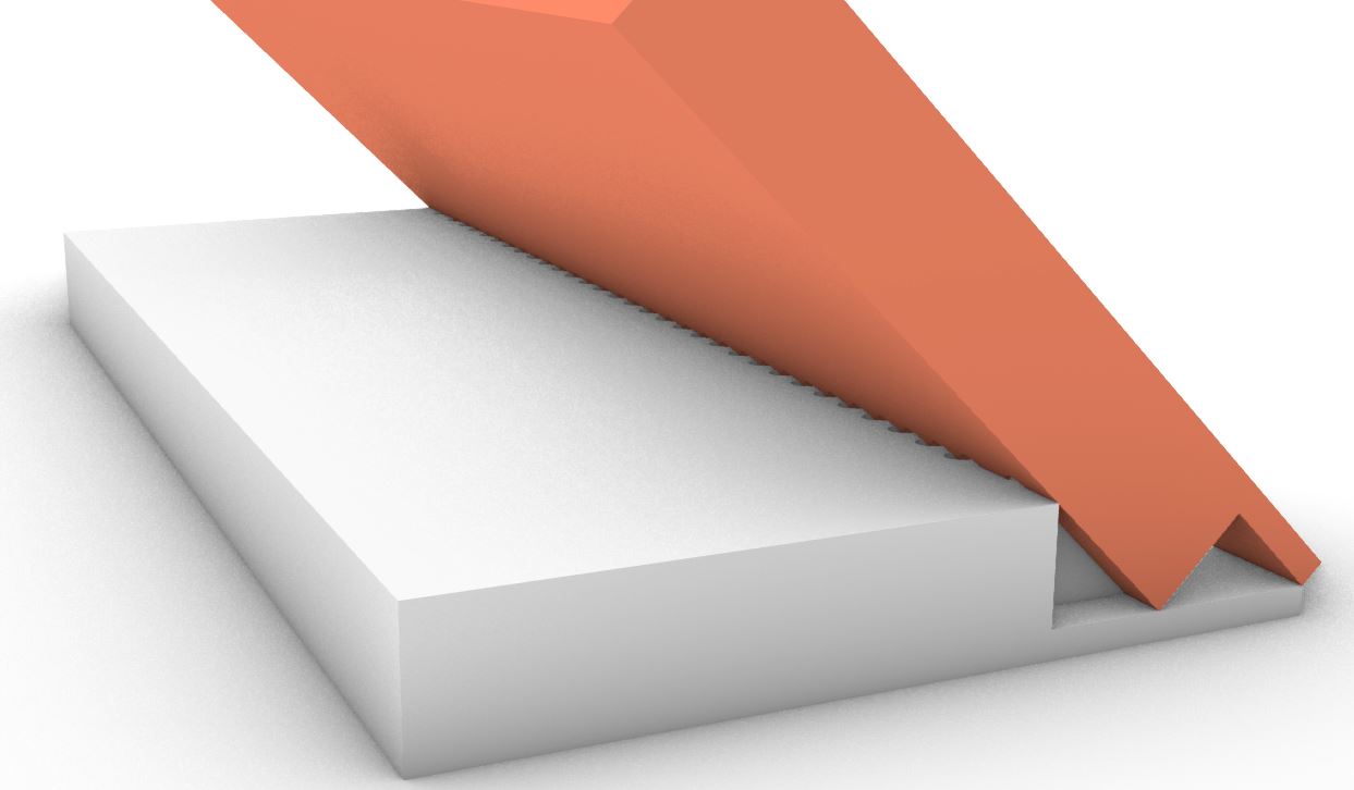
To do so I’m using rhino but I need some data from Grasshopper. In this case I’m going to take a couple of faces and look for their angle. Their angle is measured here.
from 3d faces to 2d laser objects.
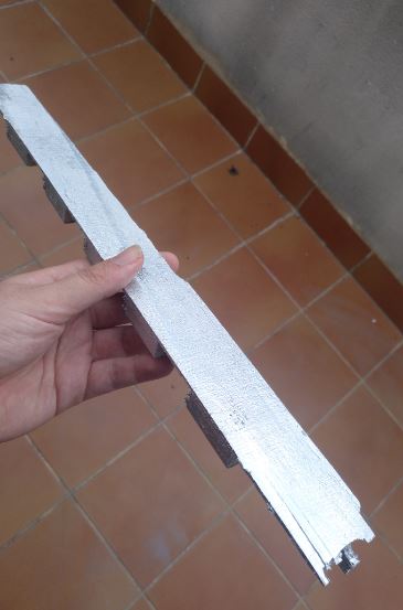
I took a couple of faces, the long side of the big one is 310 mm
I think it’s a bit too small but let’s work with that for now.
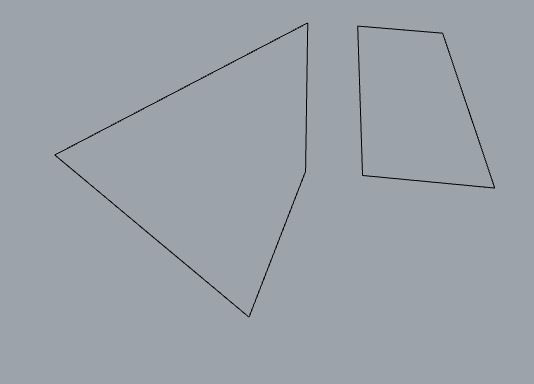
I had at first surfaces from the
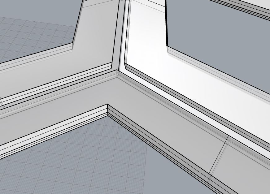
First I’m going to offset a bit (15mm) on the inside to have a clear joint between faces.
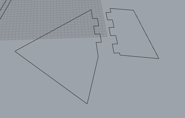
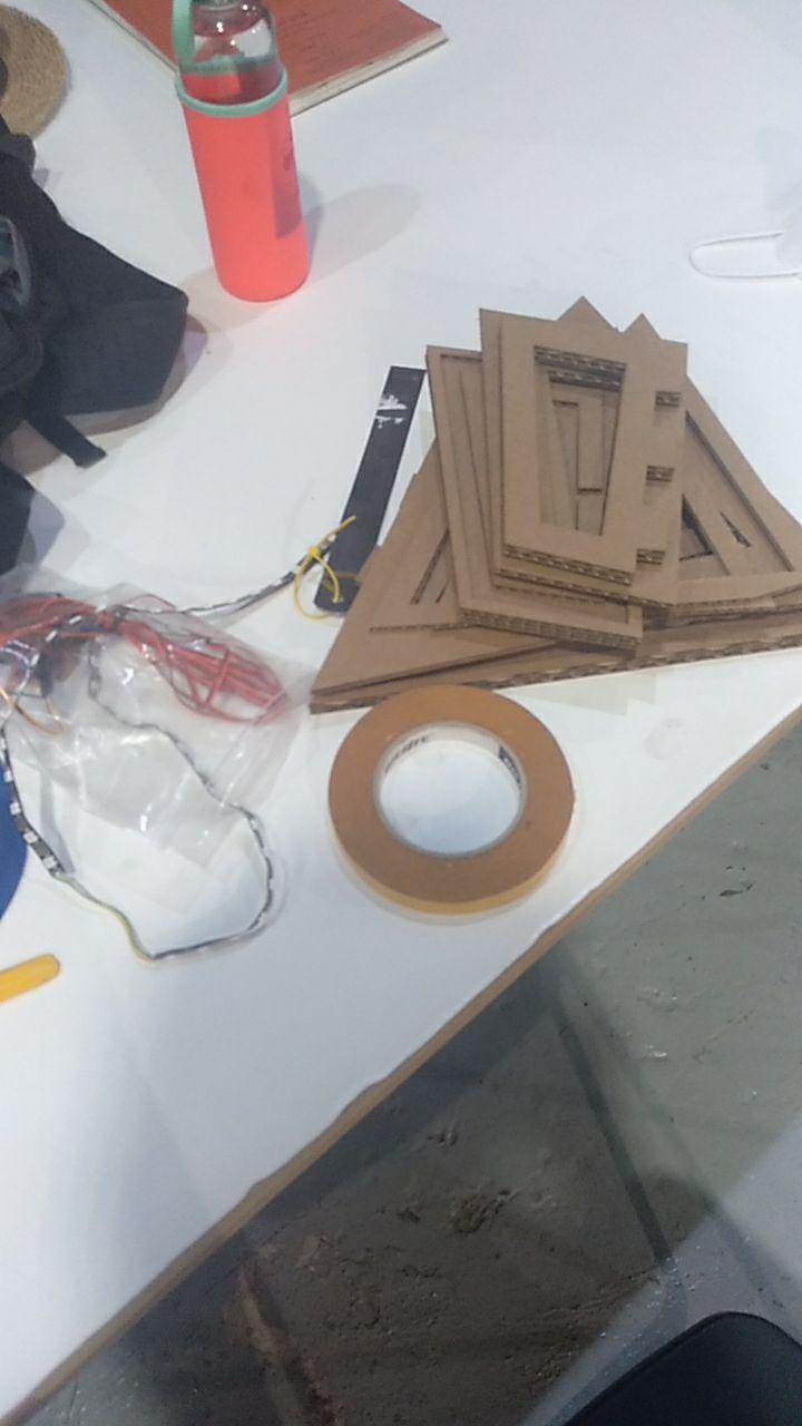
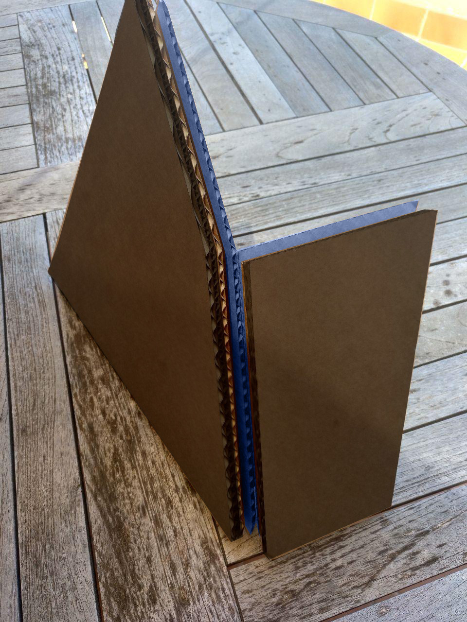
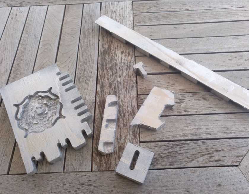
Once I have that I remember that the joint between those faces is going to be with fingers hidden. In my cardboard version. I’m going to stack 4mm boards into each other. to make some kind of this:
I would need to stack one layer of this:
and three layers of this:
I could make also with a bar structure, but for now I’m going to keep on the “solid” structure. Probably I can fit several holes on this to make it lighter.
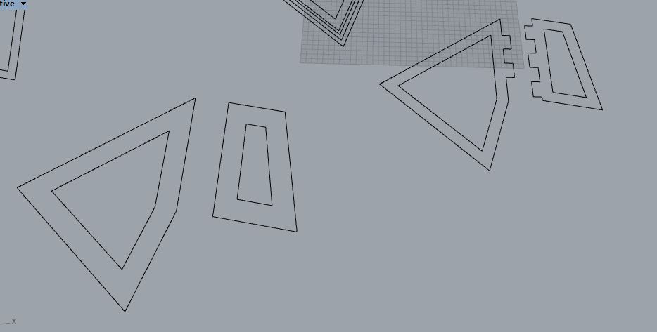
some holes have been done
Now to hide LED strip.
The LED strip is 10 mm wide and we can take that it’s more less 2-3 mm tall.
For now let’s to hide it to elevate the support by 8 mm (two layers of cardboard. with a couple of these:
And in the last layer, we add somehting to hide the LEDs and a hole to connect the cables.

More holes
And in the top, the full face three times.
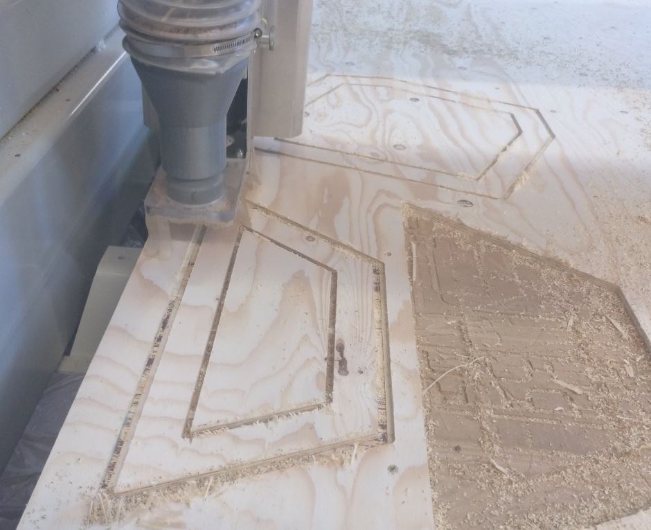
So let’s go to cut!
Apart from some scaling problems (in the trotec we print from rhino and sometimes can happen that you print the viewport (perspective) instead of top or if you set the window it scales a little bit) everything went well. Here some photos:

This is how it goes mounted:
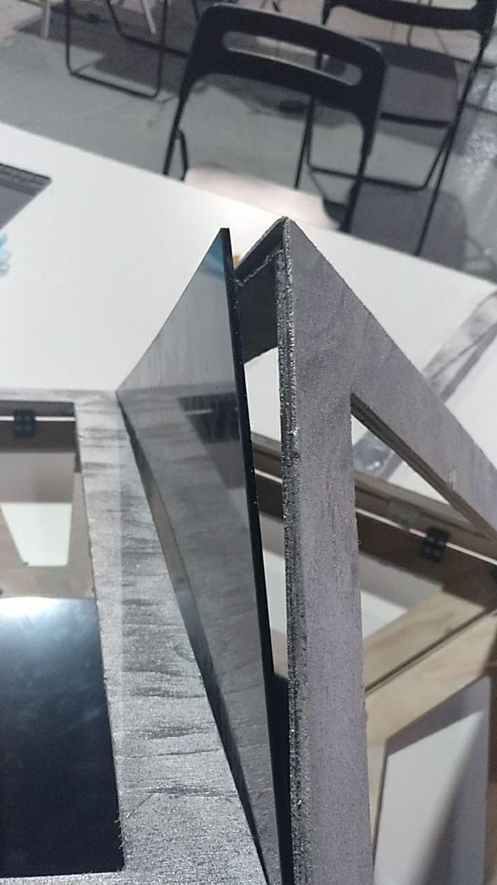
The Face layers
To explain the different layes I made an schema with colours.
Black: Exterior black opaque acrilic.
Red: Intermediate layer of milleable foam.
Blueish: 2.5D milled wood layer.
Cardboard color: courdon to hide the LEDs.
From the outside
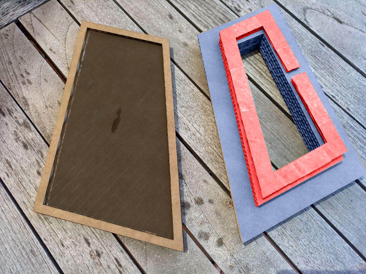
From the inside
Learn from the lasercut prototype
What I’ve learnt from this and future decisions done with this prototype:
-
The scale it’s a little bit too small. It can be 1.2-1.4 x bigger.
-
The idea for the inside wood works.
-
The exterior part will be a 3mm black opac acrilic.
-
The middle layer can be done with foam. so if it’s touched it can have some reaction. Another option it’s to add springs.
-
There will be a final layer that hides the layer that can be made of rubber.
-
The exterior layer should be a little smaller to allow the wood joint (and the reflected leds) to be seen. Maybe 5-10 mm offset.
Now what I’ve got to do it’s to make the button input.
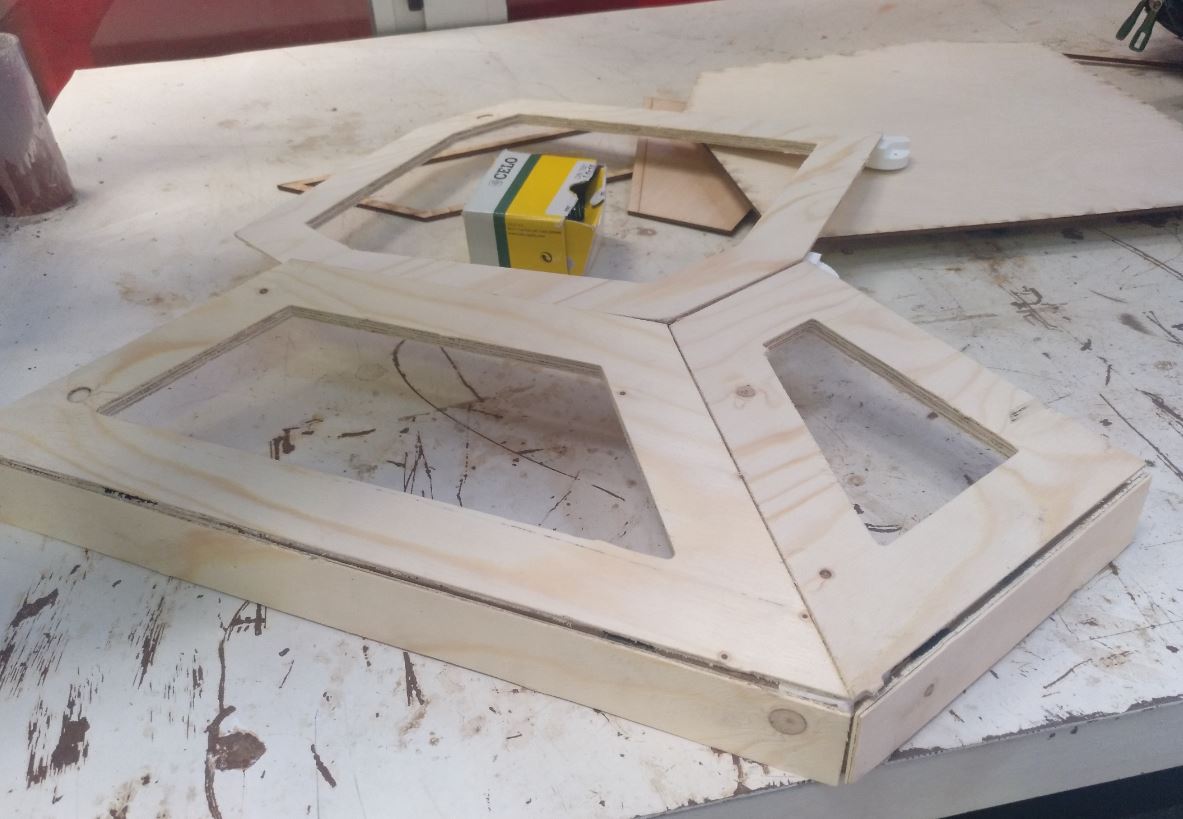
First CNC faces with hidden finger joints.
After all the work I made a version of the faces with fingers hidden to mill. To test if it worked I made only
Doing a 3D printed joint
After the milling with joints problem, I’m trying another approach. Do a 3D printed join that it’s screwed (or glued) to the board structure.
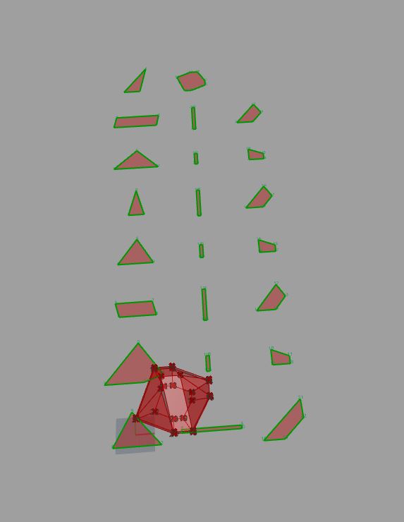
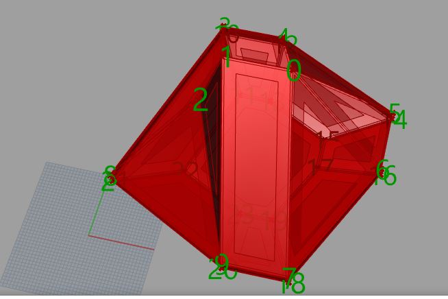
To do that I have to make in 3D the skeleton and then make the joints in 3D and print them. There is going to be a lot of them (24) but could be a better solution specially for the so flat angles of the bottom.
at least grasshopper can count the vertex for us
There are, nevertheless some problems (that are totally foreseeable) with the 8th face of the Monolith.
This one:
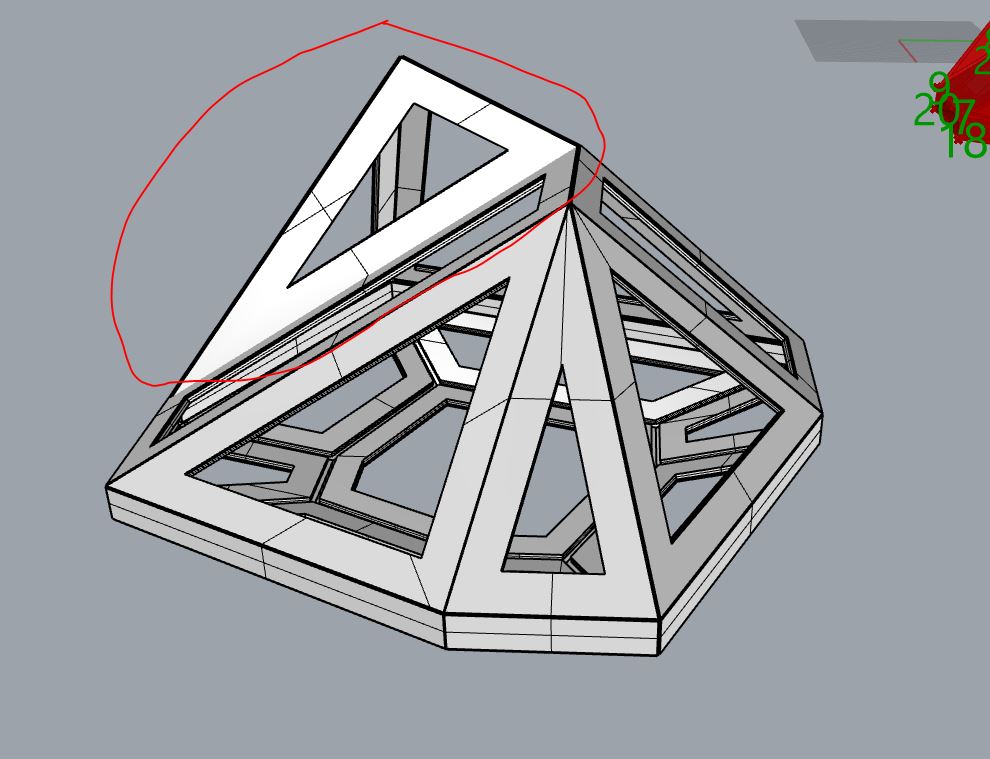
it requires special attention
It gets into the other faces so probably I’ll have to mill it differently than the others. At least is only one of the 23 faces.
Now the doubts:
-
I think use a cut cilinder could be nice because it will be easier to print.
-
I’m not sure of the size of the screws and I think I need that size to put in the design.
-
I’m also taking the in between to adjust even if I don’t plan to screw in that part.
-
Would be fine with 40 mm diameter cilinder? Would it be too much?
-
Should I use another more specific shape?
CNC-Milling the test face
Re-shape the Monolith
Now it was time for unfold the model and make a test face now in wood.
-
It had to be bigger. I used a scale of 1.25
-
I simplified the model so the bottom part was easier to mill.
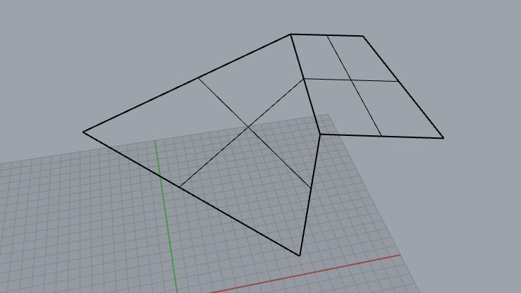
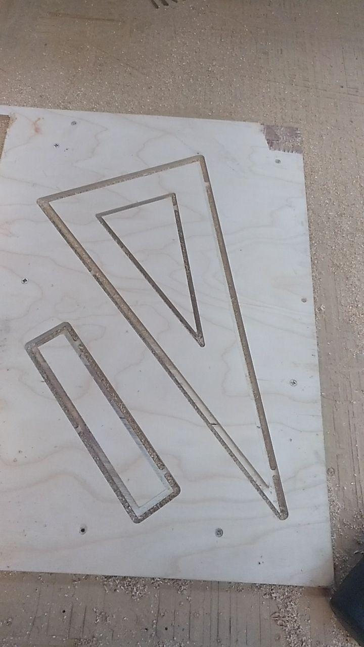
before
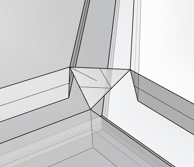
This, when I unfold the monolith geometry, led to this kind of faces that I didn’t have to be an expert to say that this is goint to be hard to mill and join:
This is a triangle that yells “NO”
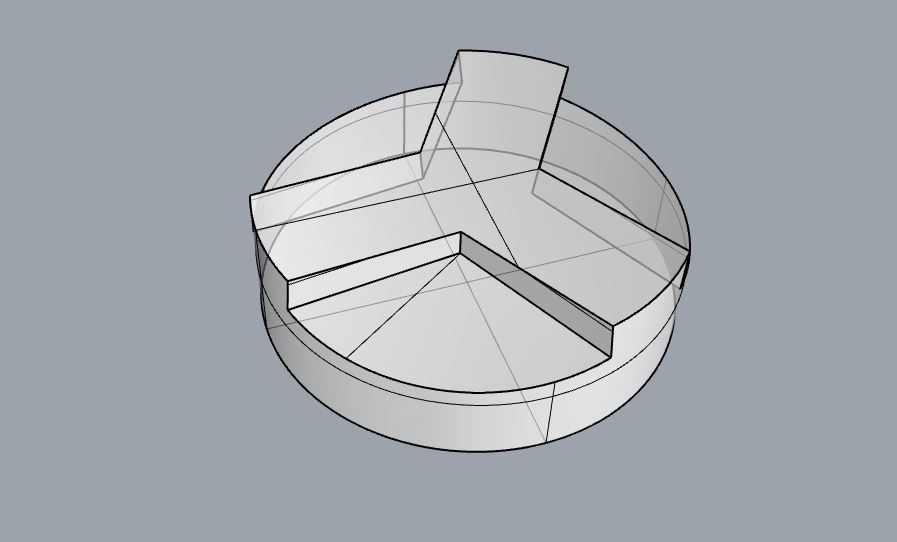
So I simplified a bit.
after
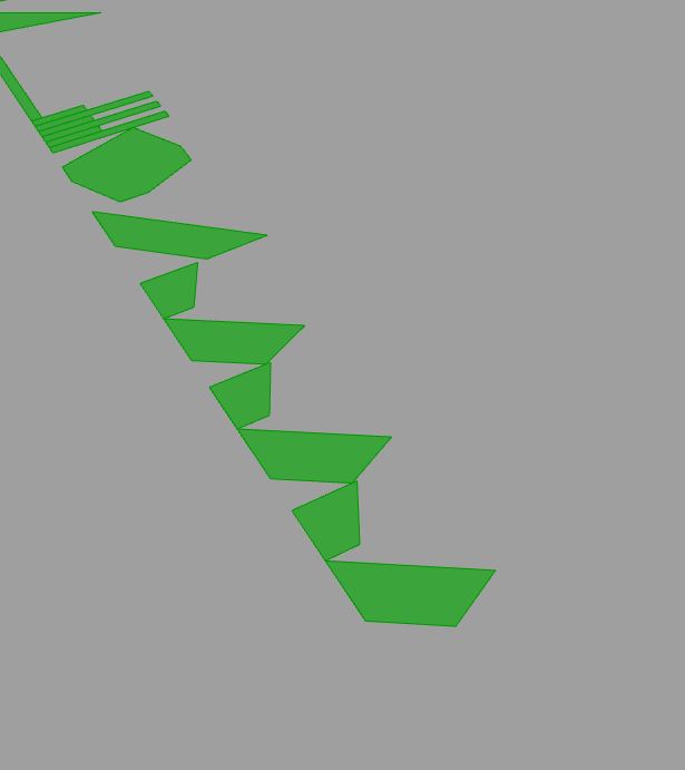
And when unfolded this was the result
It’s nice to be so regular in some parts
Unfolding methods on grasshopper
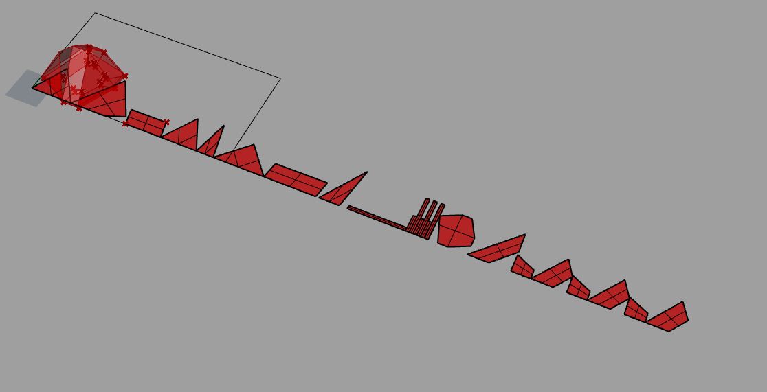
There are a couple of “unfold” and “align” options on grasshopper. Some are from plugins, some are not. You can have for example this:
separate all the faces
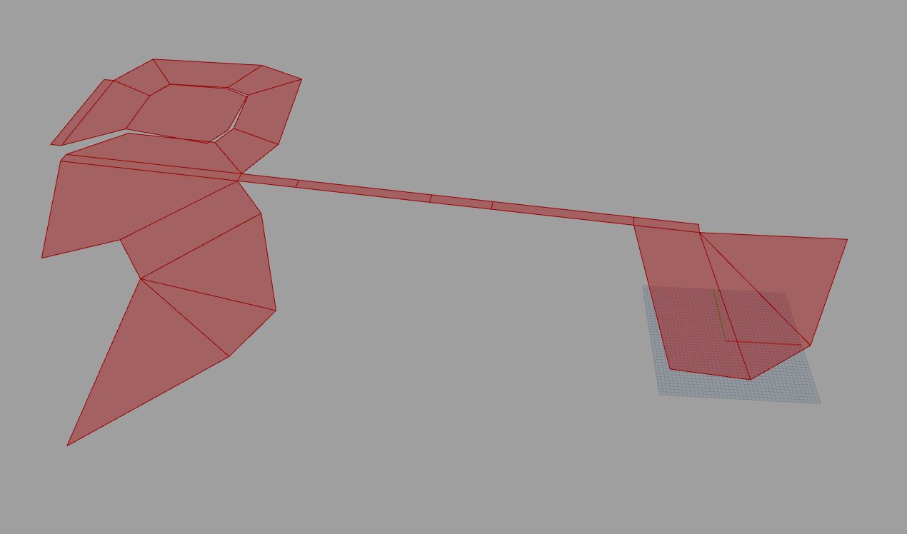
or this:
I think this was just “unfold”
After you can make a transformation to set in a sqare matrix or just bake it and then work on Rhino. There is a specially usesful comand DupBorder so you can work with curves instead of surfaces.
order!
Create the finger joints
Now looking back this part was a big waste of time, specially on the FINAL SPRINT(R) because it may be useful for someone in the future, and also I learnt quite Rhino in the process.
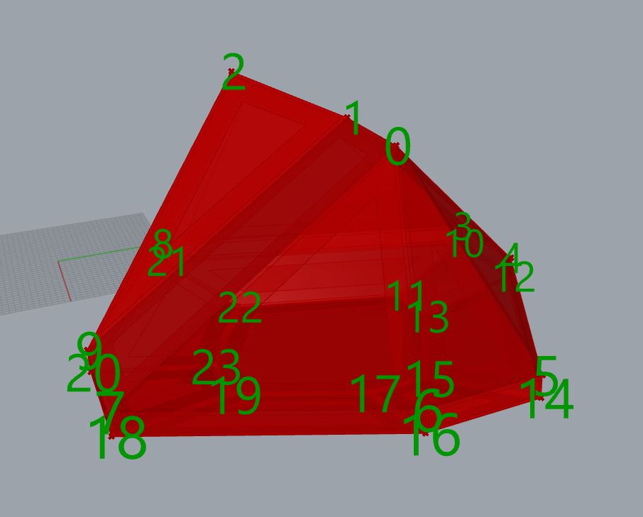
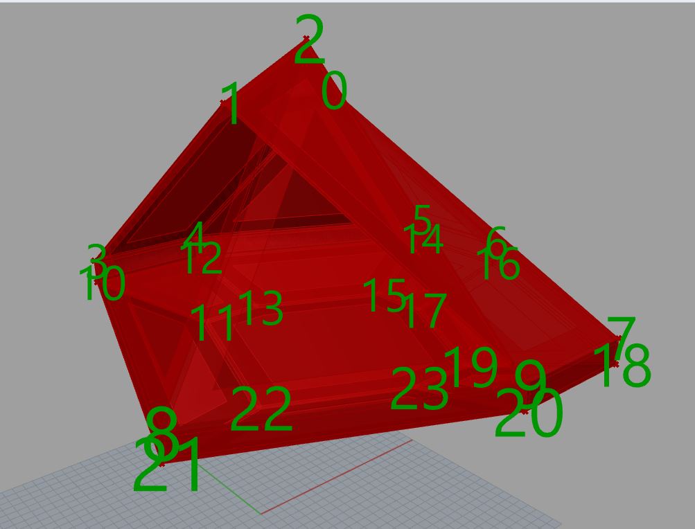
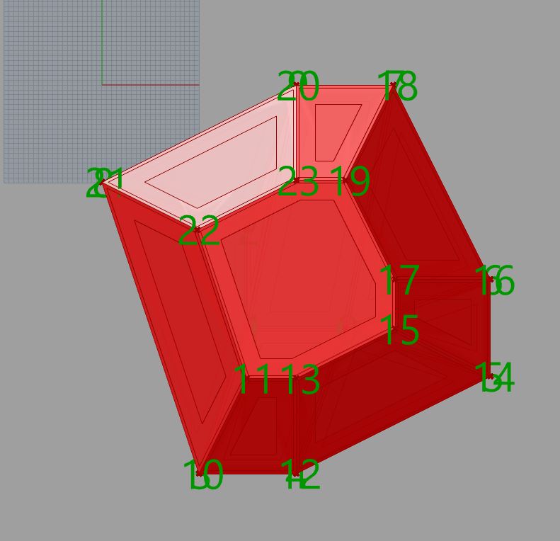
In this case using the grasshopper plugin was very complicated. So I did by hand. I set the faces on a grid and went to Rhino. I numbered the vertices so I could know where each face was.
Numbers in the 3D model
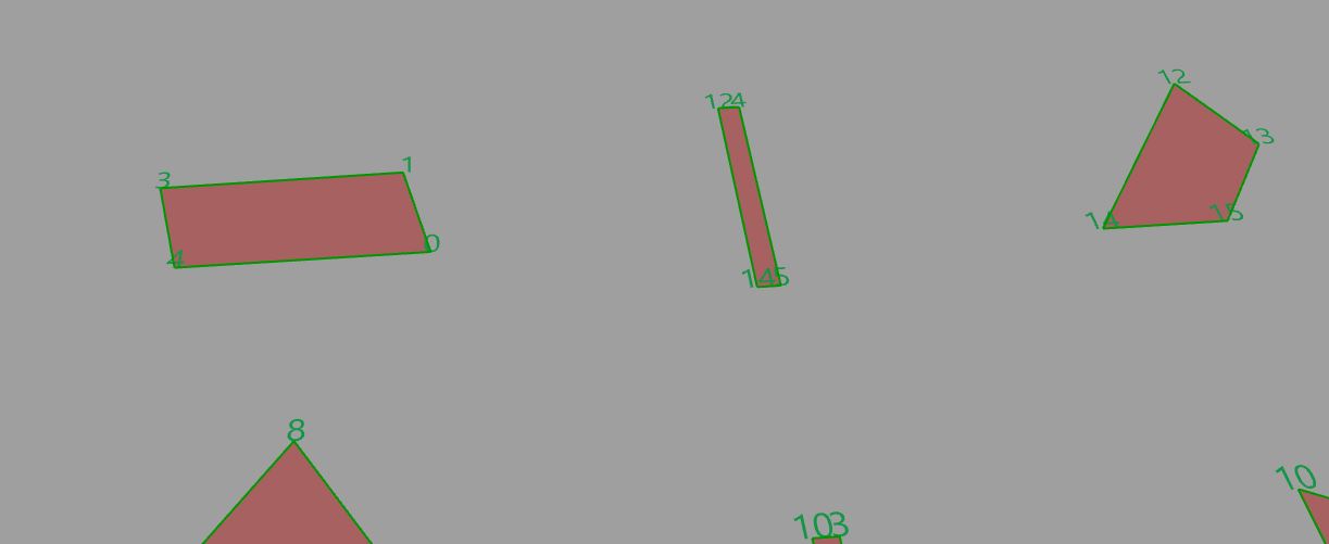
Numbers in the 2d faces
Then I started the slow process of set all the offsets.
In this case I needed the line I want to profile, and 2 for the hidden pocketing. Also I needed 1 for the internal profiling. I didn’t know yet (because I know more about CNC now) but I started with all the joints.
Those were a lot and there were like 20 hours of work. 0/10 would not recommend. But I’ll explain anyway.
I divided the faces in 3 sets. The bottom regular part. The middle faces and the top irregular faces.
I decided to start with the bottom and the middle faces between the top and the bottom.
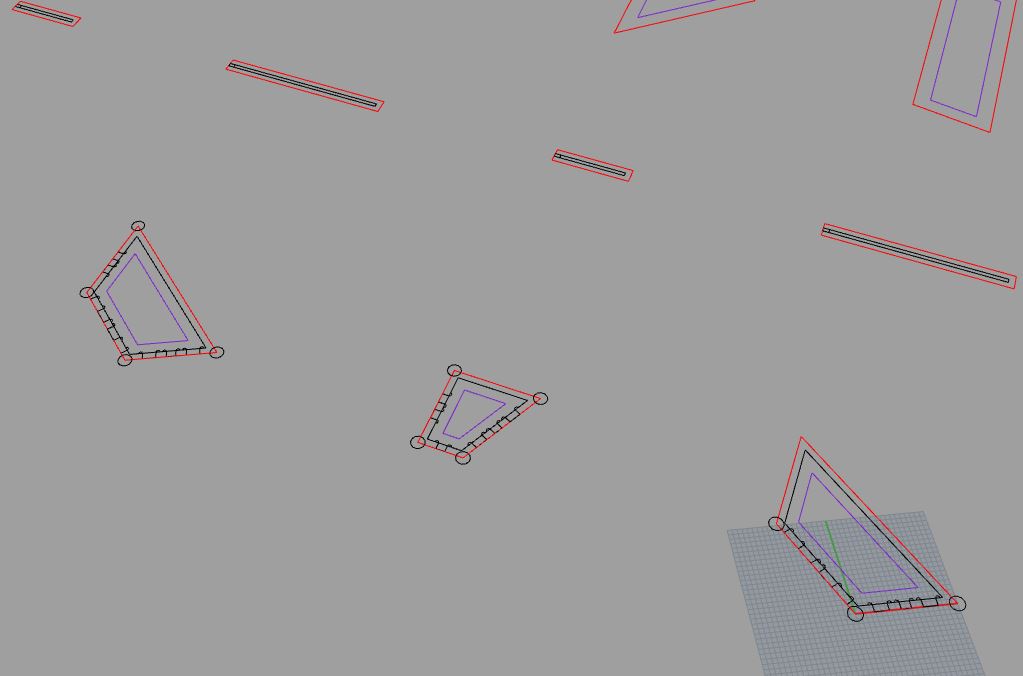
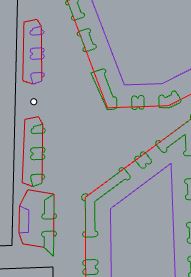
Irregulars top faces on the left. Bottom on the right. Middle face, well, in the middle
I had the faces in red and I made an offset. That was the offset for the pocketing that I’m doing. Then I planned to trim it as it were necesary.
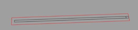
long piece is long. Red means external profile
For the middle faces I just made a finger in one of the short sides so they, kind of fit together?
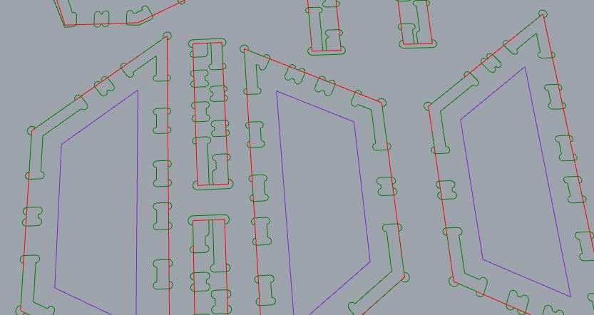
Then, for the bottom pieces I added another offset of internal profiling. Then I added some circles on the corners because I didn’t want to mess up 3+ joints so I kept to the inner circle.
purple means internal profile. Red means external profile
Then I started doing the finger joints. I made a symetrical drawing taking into account the extra space for the pocketing that the CNC needs.
Mickey ears
Then I go to the other side and I reverse the drawing. And I keep doing it for all the sides
This is the process
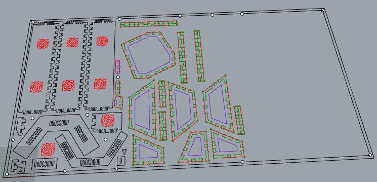
It took me like 1 full day just to do it. But I made… not all the faces but all the regular ones and some irregular (That I needed to take into account another parameters).
But when I arrived to the lab I realize that this a good template to work with. But I needed another kind of drawing and the mickey ears needed to be all around the other side of the wood. So go back to draw them.
The result was like drawing some kind of bones. This is the result on the board to cut:
they are too similar to cartoon doggy bones
I made a test figure also so I can test the kerf and tolerance
Test joints in the CNC is very important
I used the same board that I had the last day (and it was screwed to the sacrificial board) to make the CNC assigment. The board was still the same, a 15 mm plywood with layers of 3mm.
After this I added more screws
For the CAM process I used the RhinoCAM software installed in one of the computers of the lab because it was more convinient that use my own (heavy) laptop. Also I could ask Josep any doubts that I have and he or any other instructor could check the cam settings easily.
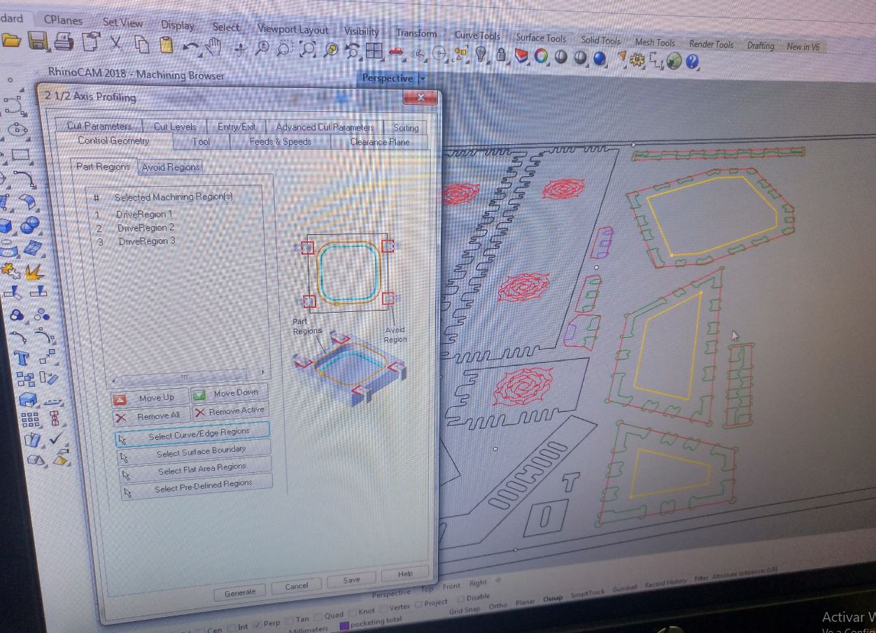
Cam setting
Test cut
First for the finger join I made a couple of test with several distance of tolerance (0,4 and 0,6mm between the in and the out).
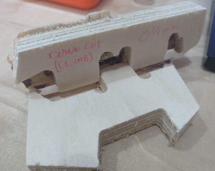
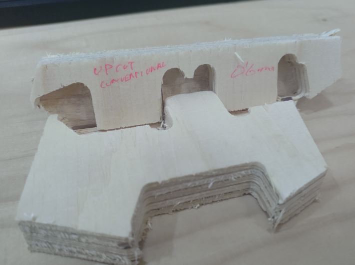
Write in the test is a good thing
So I finally used Convencioanal upcut with 0.6mm of space in between.
Cutting process
Now I was ready to cut. Since you need to keep an eye on the CNC and it take some time. Once you launch the file it’s the perfect time to have a snack.
Purrfect timing
Also it’s important to take a photo of the home (specially in XY) of your board because if anything (energy shutdown or something) you can get it back. Also, it counts as an image for documentation!
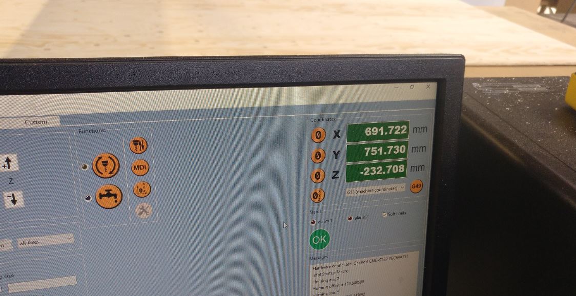
Back up in pictures
The process was long and when it was bout this point:
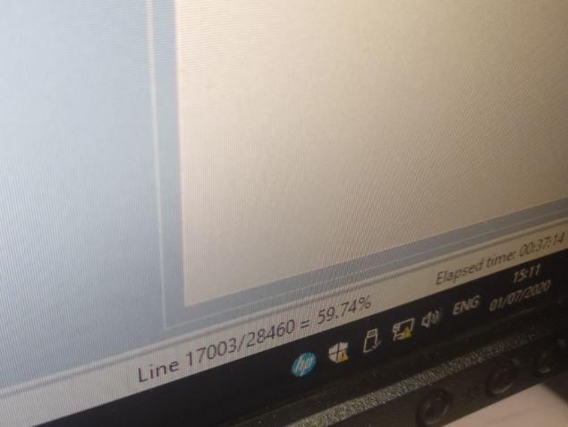
I had to stop it because I set the internal profiling as a pocketing instead of a profile. That it’s not incorrect per se, but it was going to take waaay longer and also it’s more use of the mill. So I stopped the machine and redo the files I had to send.
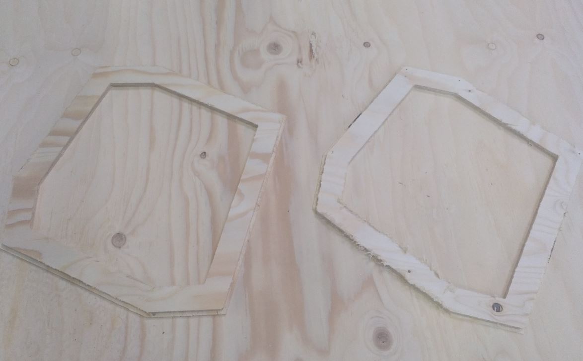
Result
This was the result, the fingers weren’t perfect (Because the 15mm board also it’s not the very best one), but hey, they Fit!
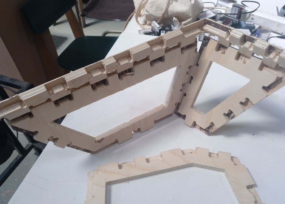
It holds together
The 3mm exterior was kind of rough also
more-less fit
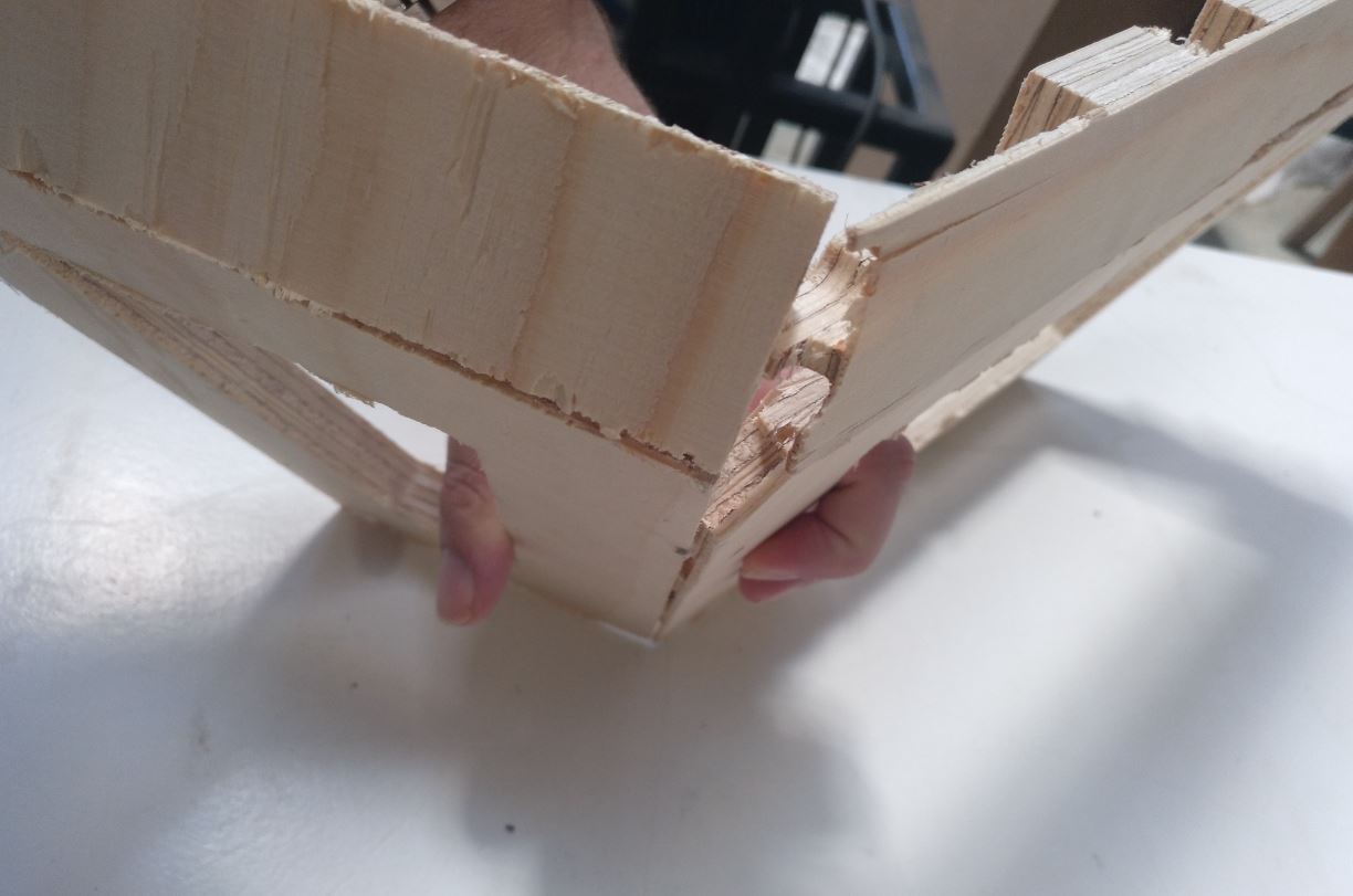
But there was a bigger problem The bottom part was… kind of flat. This finger joints didn’t work with those wide angles. So I should make it again.
And the clock was ticking.
Reestructure
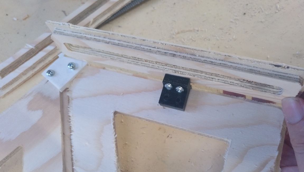
Eduardo, the instructor gave me the suggestion of instead doing the finger joint, make the joints via 3D printing and screw them.
Because the adjustments of all the faces in the first place took me a couple of days only doing that.
So he suggested to use a thinner plywood (9mm) and use 3d printed joints with holes on them.
I was very frustated because of the time that the finger joint consumed. So I accepted. Now that I’m more calm maybe it could be solved some faces with those printed joints and others with fingers buuuut it would also needed time and clearance of thought.

Incoming deadline
So I thanked Eduardo for his advise and started designing the 3d joints.
3D-Printing. Designing and printing joints
So let’s get started!
Concept and speed design
So I neeeded the exact position of the pieces. At least the boards now are way more simple.
Each face is 9mm thick and it has a 6mm offset of 3mm and a hole so the solid part it’s 40mm wide. With that in a relatively small time I have a 3D version of the board. This one:
I used already because magic of exposition
Now I can go for each of the… 27 joints and make something. So I started with the bottom ones
This is going to take long
First I made a plane to work with.
3-4 point surface tool
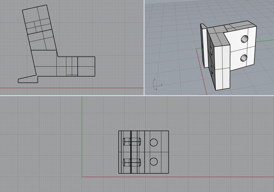
Then I do a cylinder big enough (50 mm diameter) and I start doing boolean operations to subtract the faces where it has to fit.
cylinder gonna cylindate
This is the result when you flip it out.
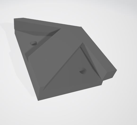
Now I added 3 cylinders perpendicular to the respective faces. The hole was of 3mm because Eduardo told me that was the size of the screws (I met those screws later)
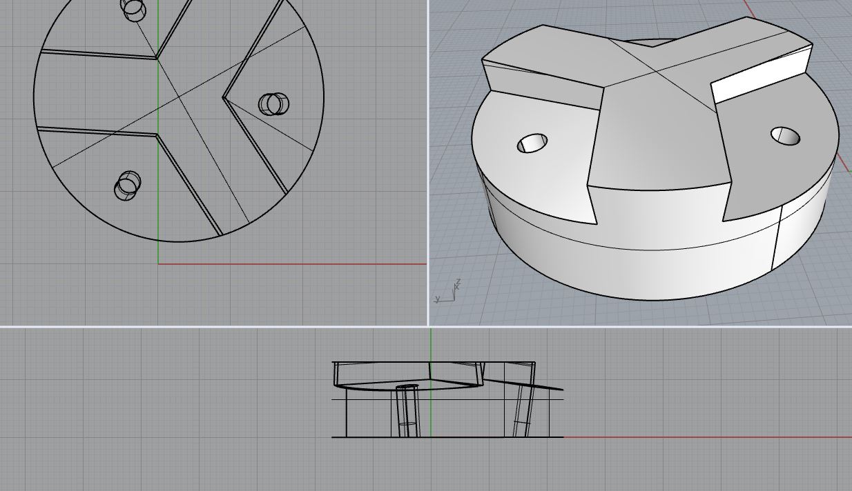
You can see that the cilinders are aligned to the pieces and not to the based where it was going to be printed
Then, to the print machines that we need A LOT of joints in not very much time!
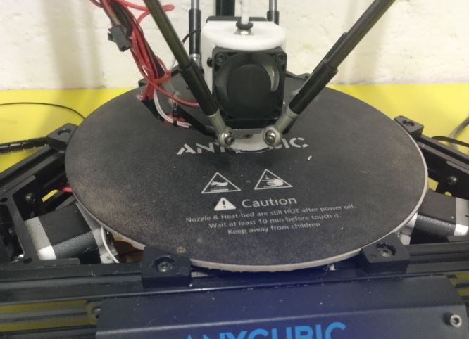
GOTTA GO FAST
Testing
Now when I tested the holes were too small, so I went from 3.0 mm to 3.5 mm so I don’t have to screw them 5 times before the screw passes through
Also I was going to have a HARD time with the joints of more of 3 faces. Or too pointy. So first I decided to make several joints more specific.
it was done on Rhino 6, but the STL viewer is from windows
It was… too complicated to design. And it would be a lot.
So I decided to go for a 2 side joint and duplicate it. For all the joints.
Mounting the tests
These were the screws of 3.5 mm I was going to use.
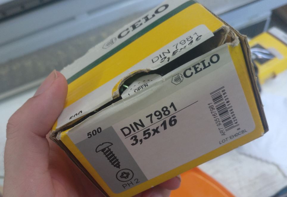
Screw it!
And all from it was without sanding. I was going to have time to sand while cutting the rest of the pieces and the 3Dprint ends. Also I had to repeat a couple of faces.
This is from the outside
Here you can see hte small corner joint in one of the sizes. And some damages in a couple of faces.
Repeating some faces
A couple of faces were not properly milled. We deduced that it was due to not proper screwing that allowed vibrations and… well, that happened. So go back to the CNC
CNCed again
And you can check the differences between both
2 pieces in front of the board
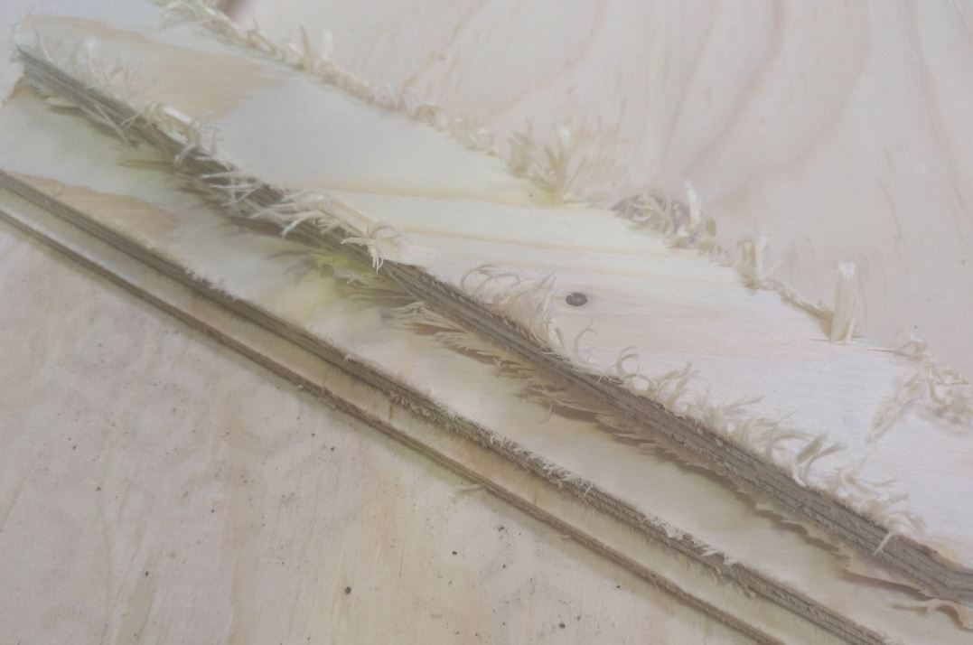
Detail of the differenca of the sanding work ahead
Also the 14 from one sit was a good idea because these took less time to be printed so yay.
14 of these please!
Thankfully I could let the 3D printer do all the set in one night so next day I could continue.
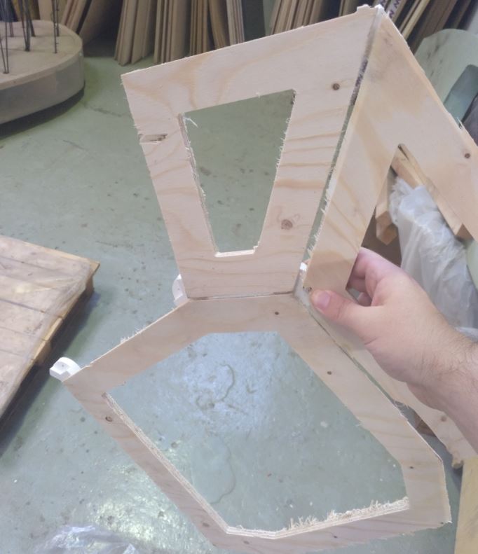
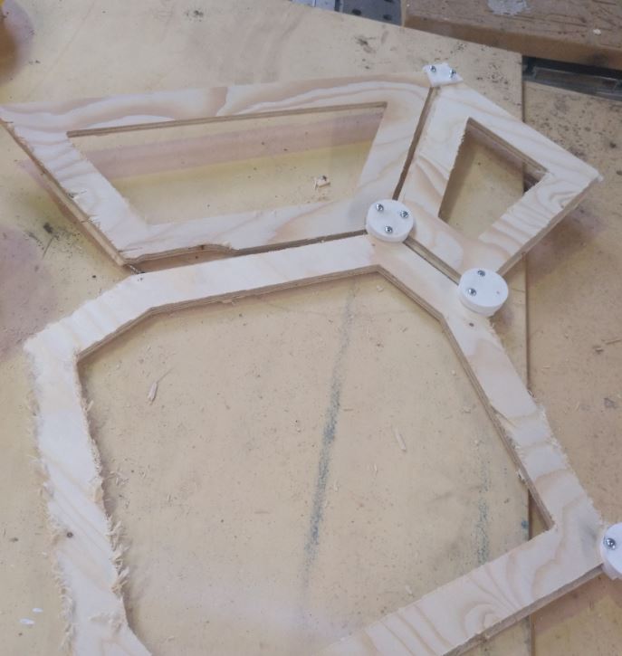
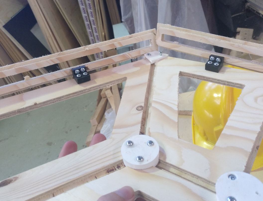
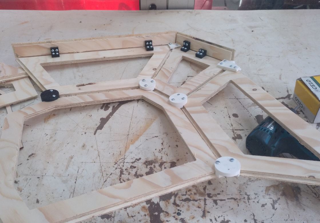
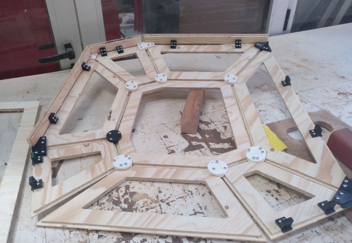
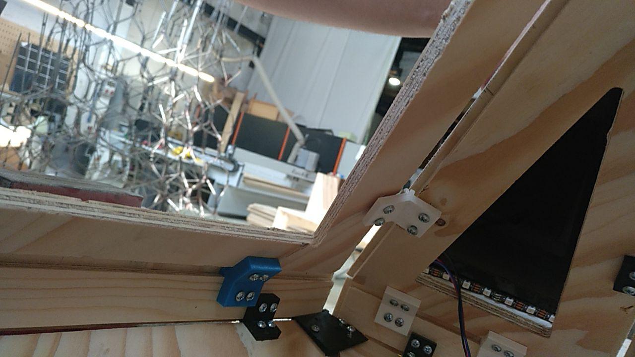
When I printed the 3D joints I could make 14 (2 per side) of the 7 bottom faces. They fit but I saw that those pieces of wood were too fragile. So I remade them as solid wood (without the hole).
Here we can see how the joints function more less fine (thew will work better with a little more space) but the frame was to weak.
_
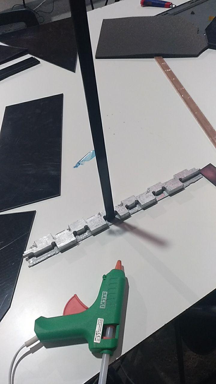
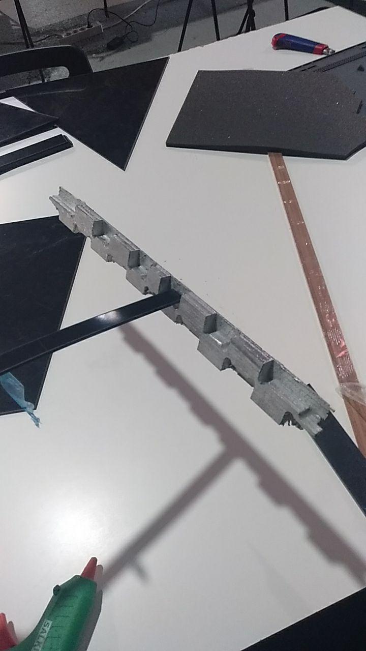
Process
Now getting ready for another session of CNC Milling
I have to be feeded while cnc cutting
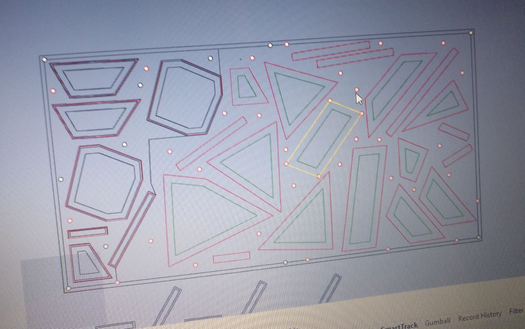
So once the test is done, now we have to mill… all the rest of the pieces. For this I used also deepnest.io
I simulated also the fragment of the Board I had left. I just put the regular shapes and from that I made in Rhino all the offsets. I could fit all! yay!
Also lots of screws
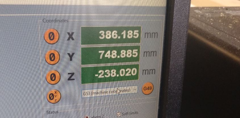
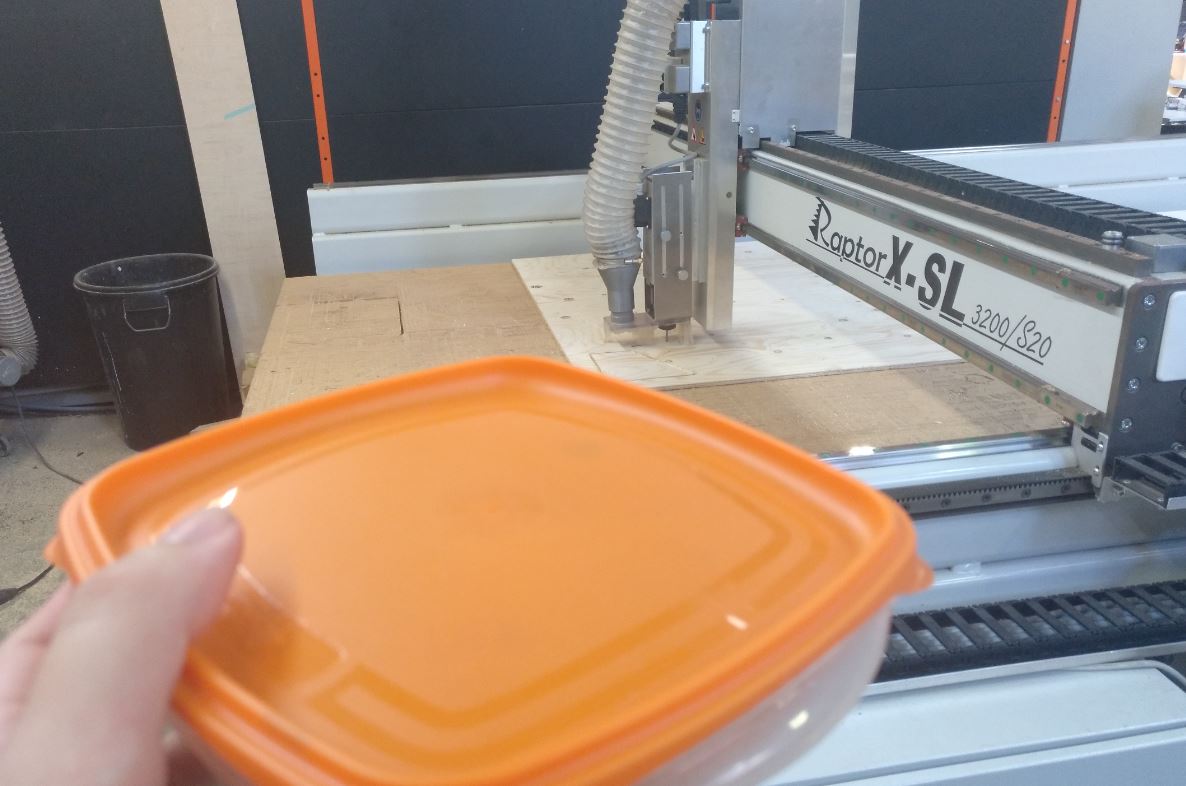
Mandatory set of X and Y of the CNC Raptor in case it needs to be reset.
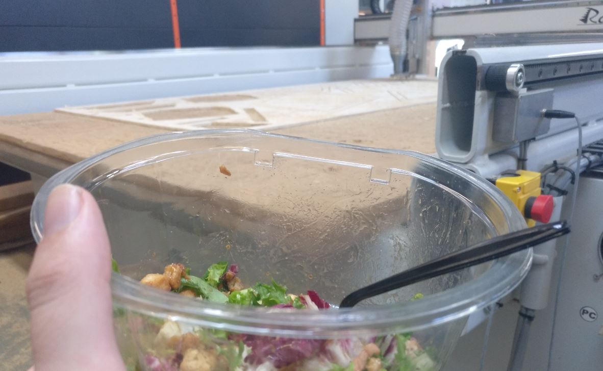
Now wait 2 hours ¡Que aproveche!
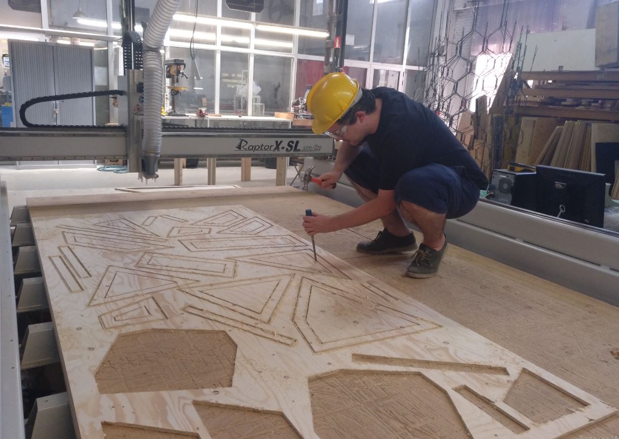
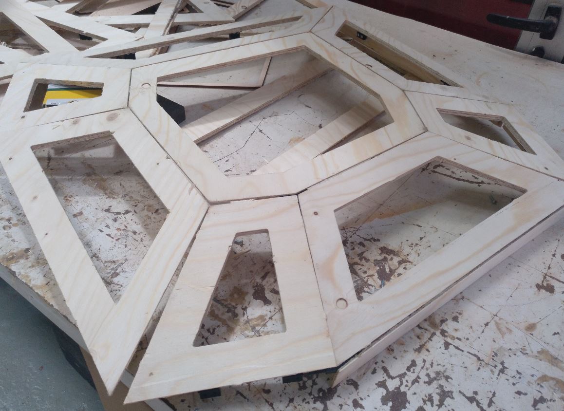
Now time to take out the pieces as if it were a giant new boardgame
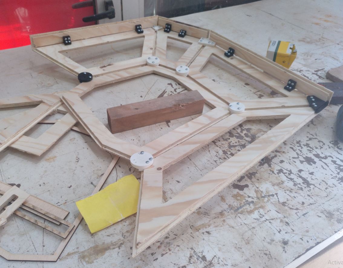
And now mount. I would sand and print more joints at the same time. That was a rush time.
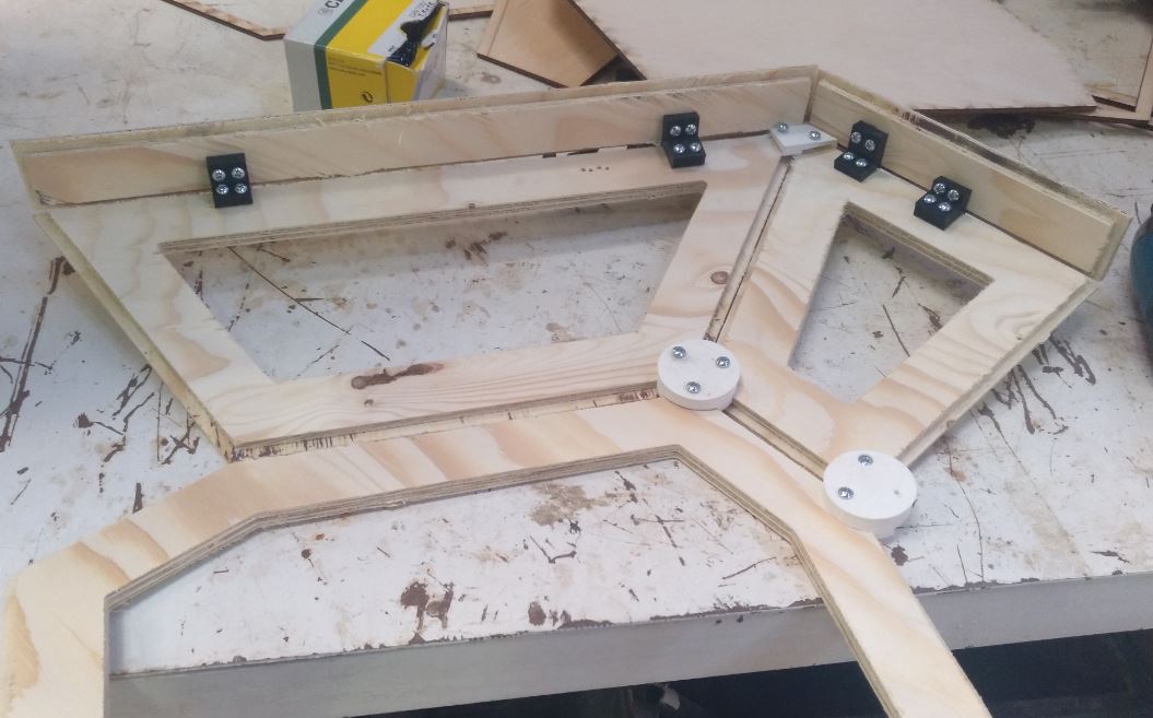
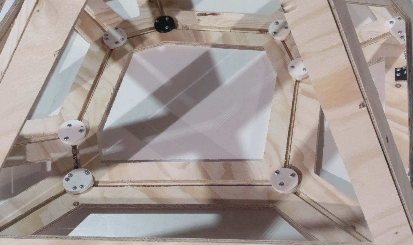
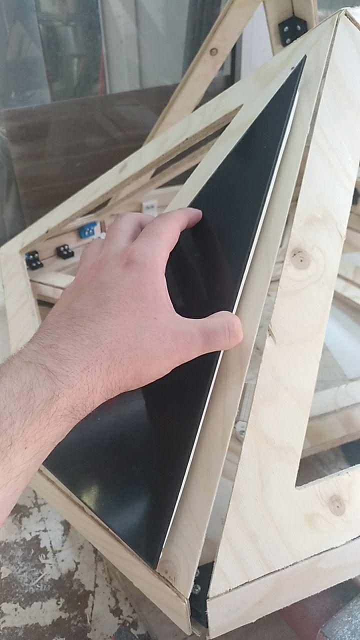
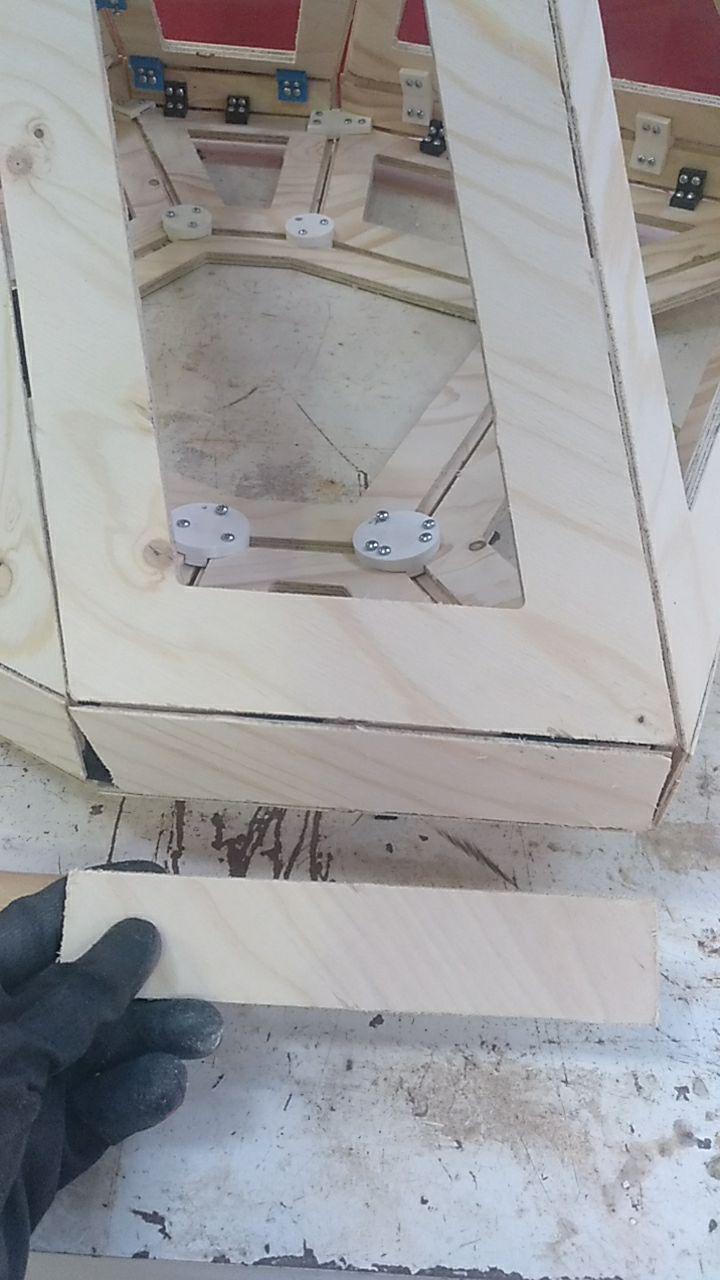
Here the solid sides were much more fitting
Also from the exterior
Now it will unfold using the picters as you scroll it through!
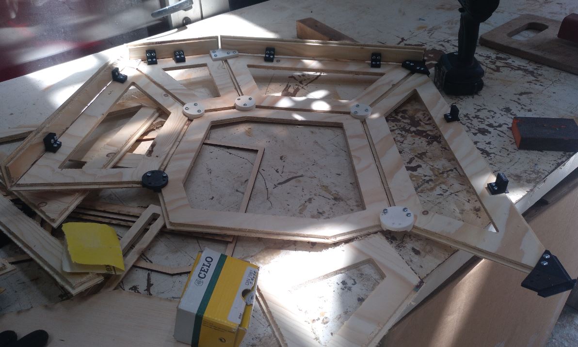
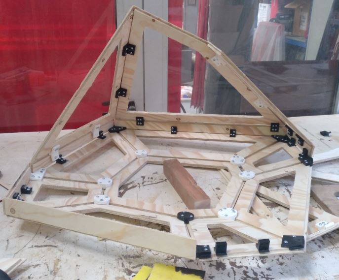
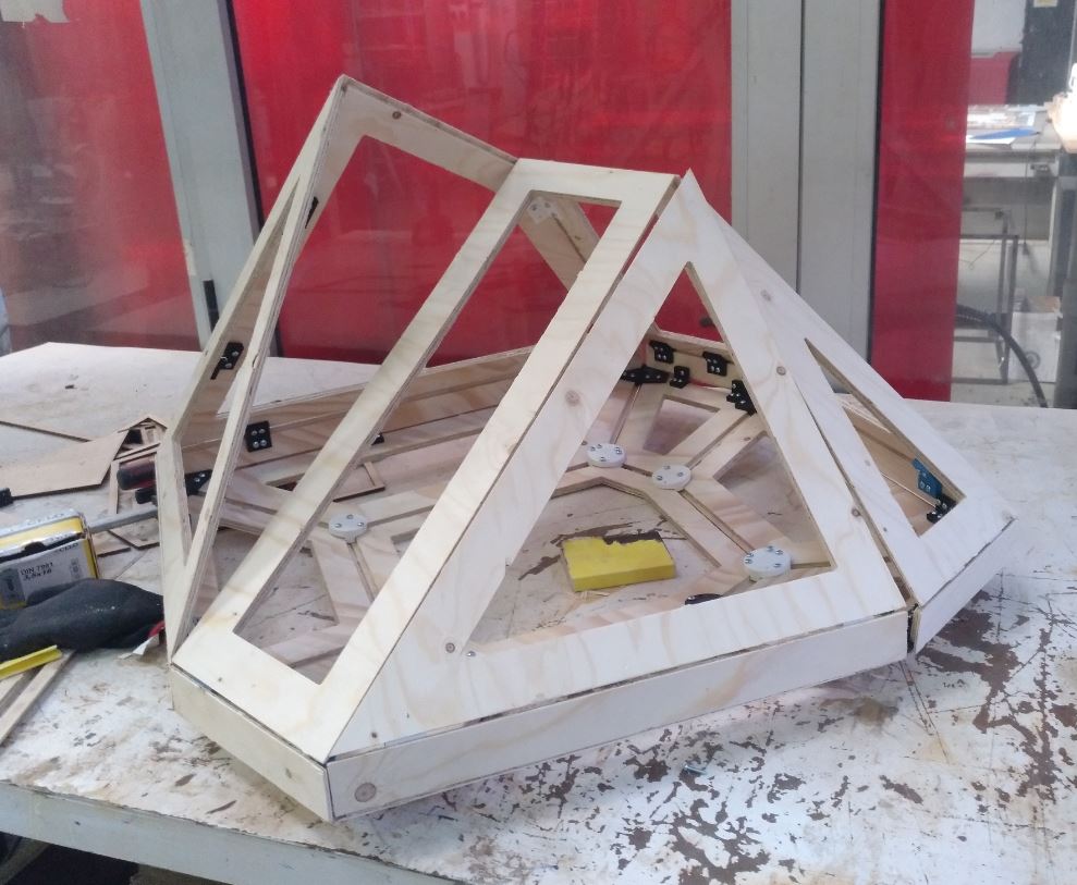
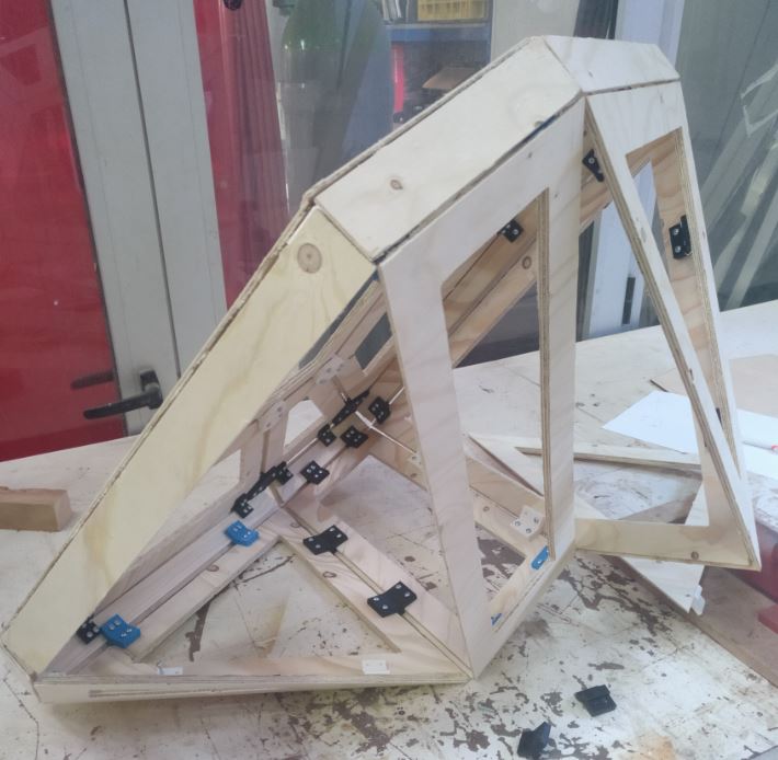
Interesting trip, isn’t it?
The difference between the colors of the joints it’s just the color of the PLA that was available in the machine. It’s not meant to be seen so I could afford any colour.
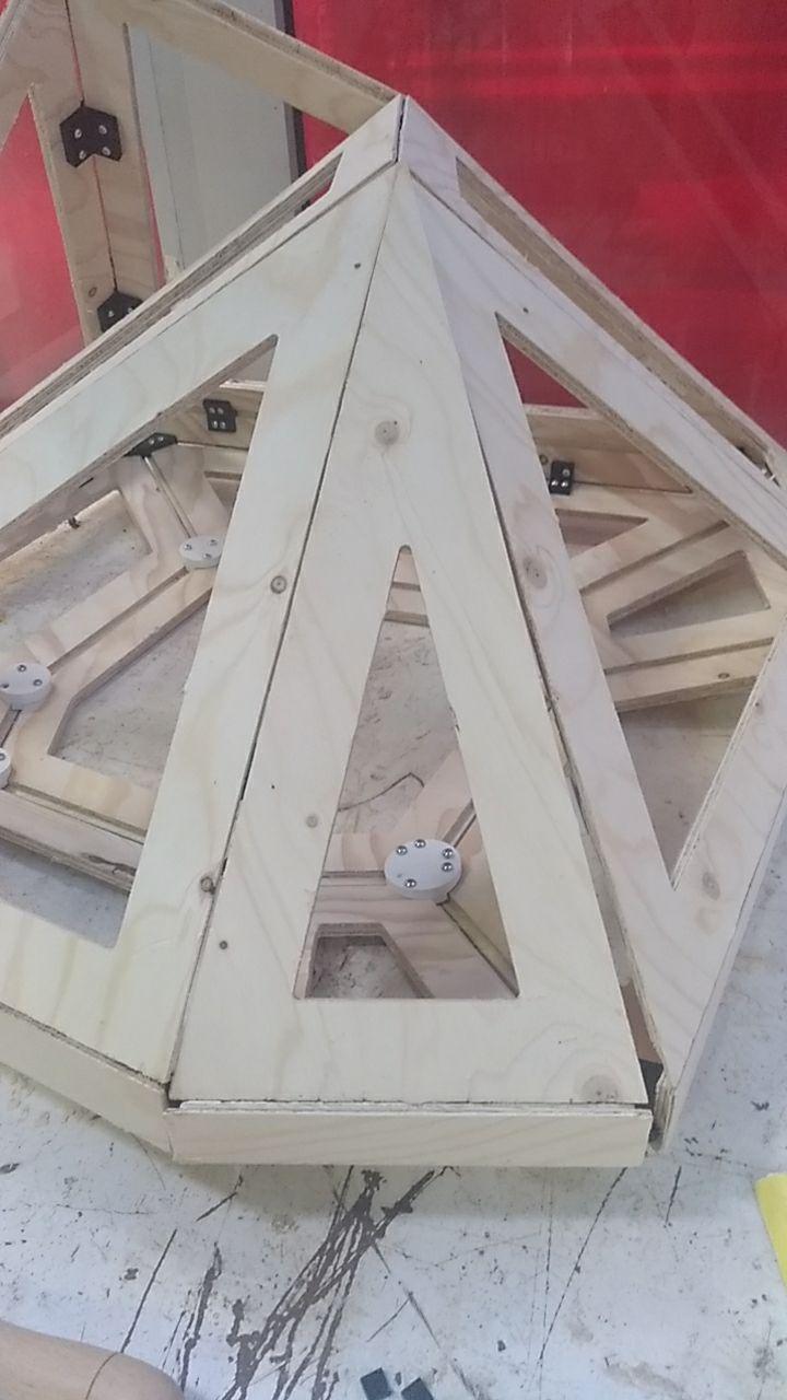
And this is the:
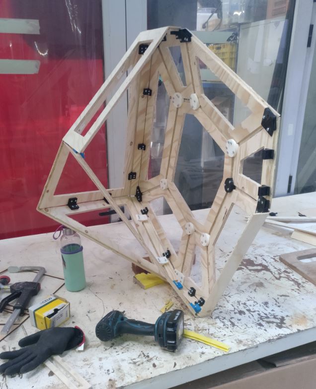
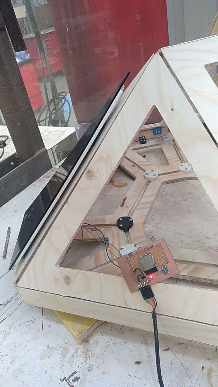
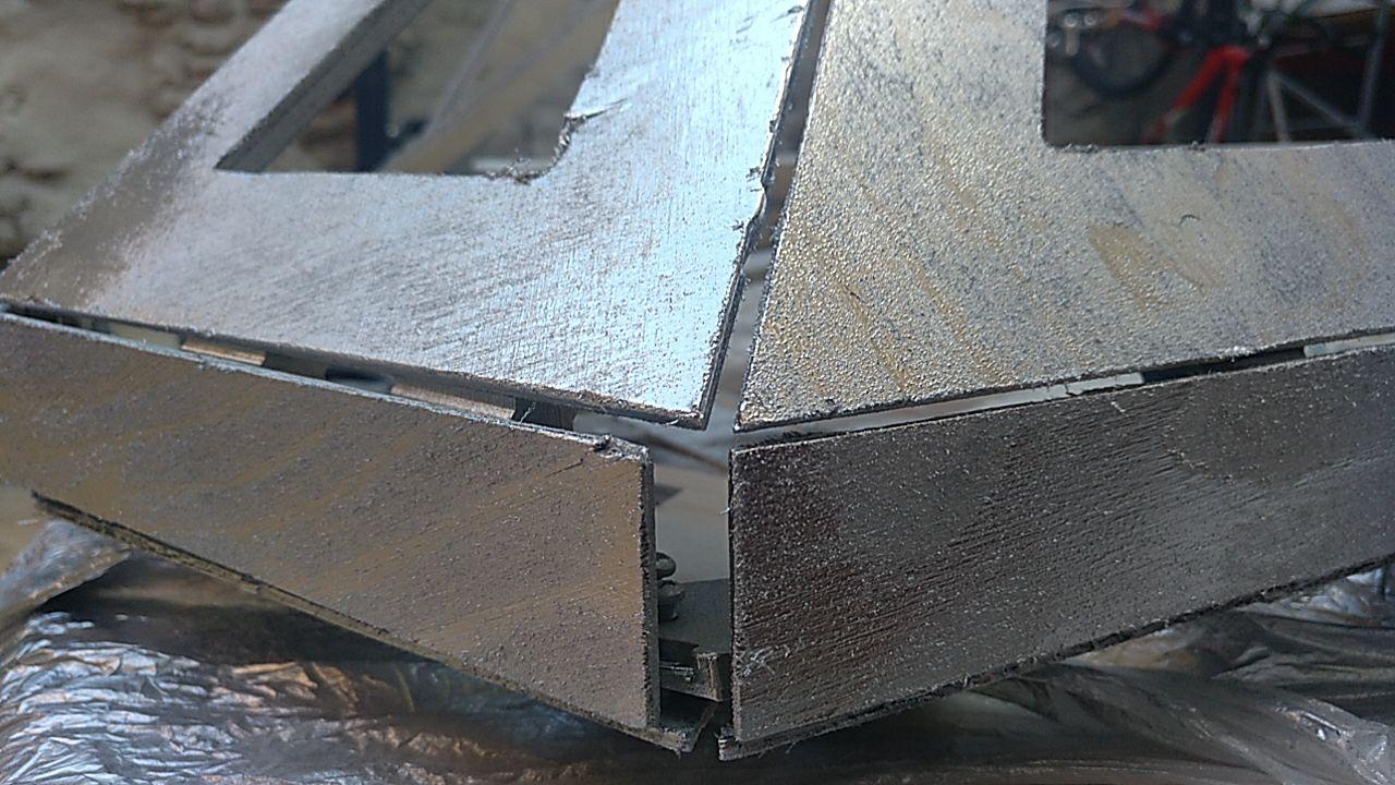
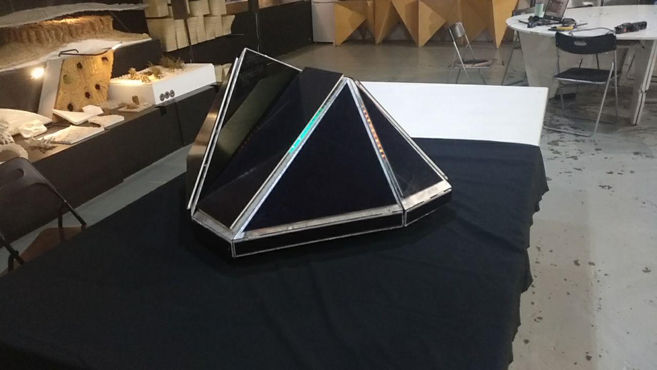
Frame finished
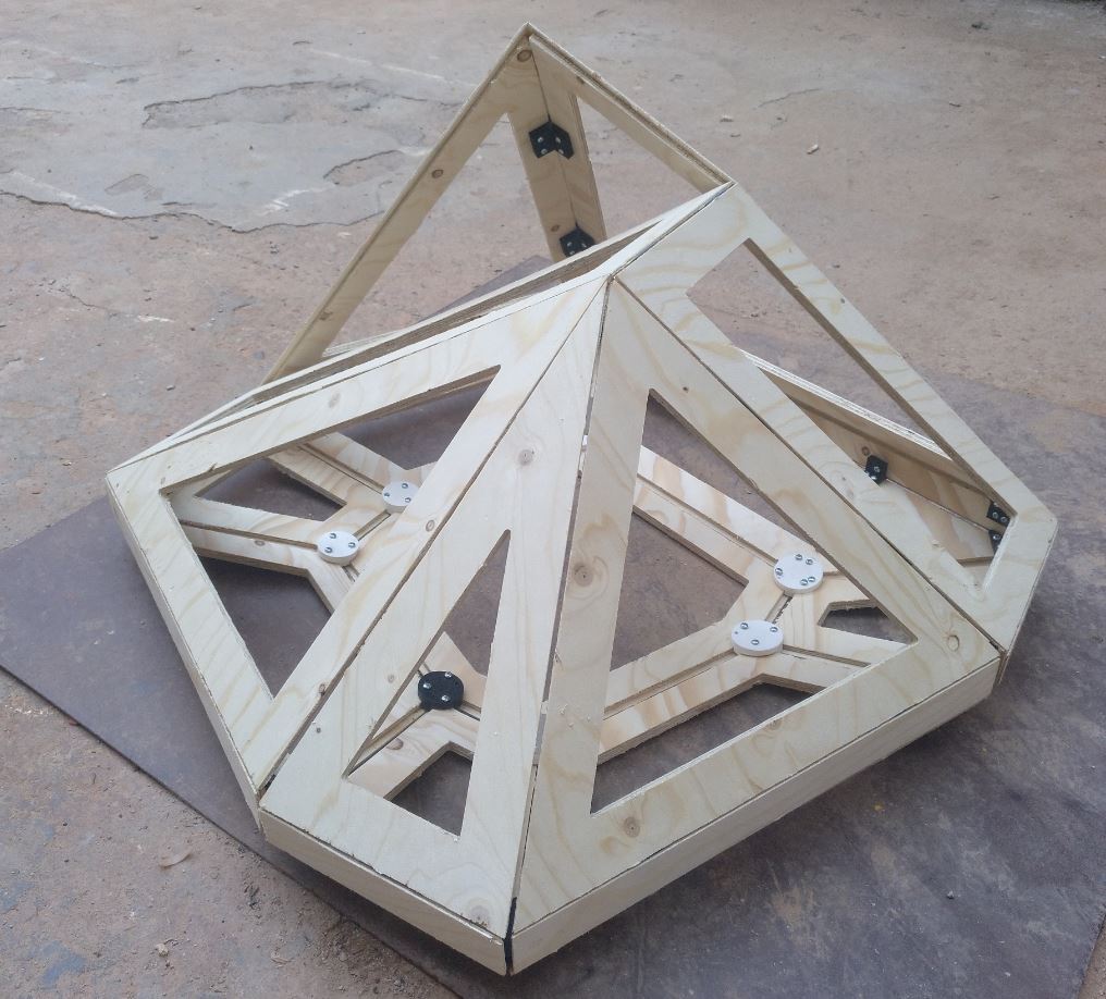
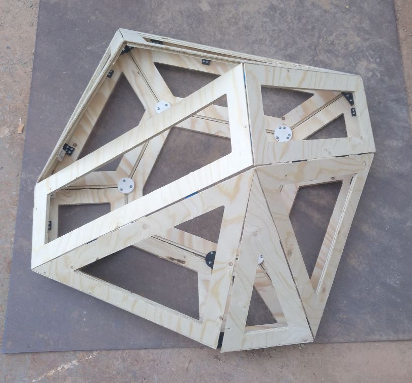
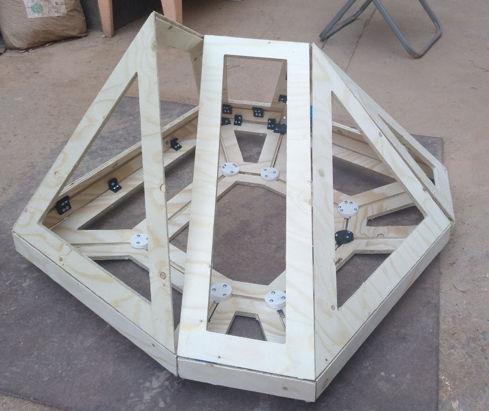
Beautiful < 3
Test face. The button problem
Now that I have a chassis, I had almost everything clear in my mind. Except one thing. The buttom mechanism. With that I was totally BLOCKED.
Luckily the instructors helped me and told me where I could get some material to experiment. I also had antracite to make the button smoother.
I made one of the bottom faces, because even if it’s not going to be pushable in the end, I had the face cut in laser from previous tests!
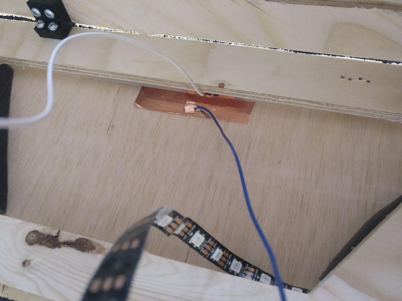
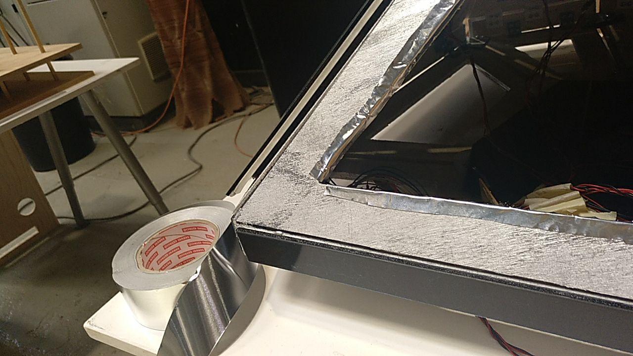
So double-tape for the polyurethane foam (you can check it here)
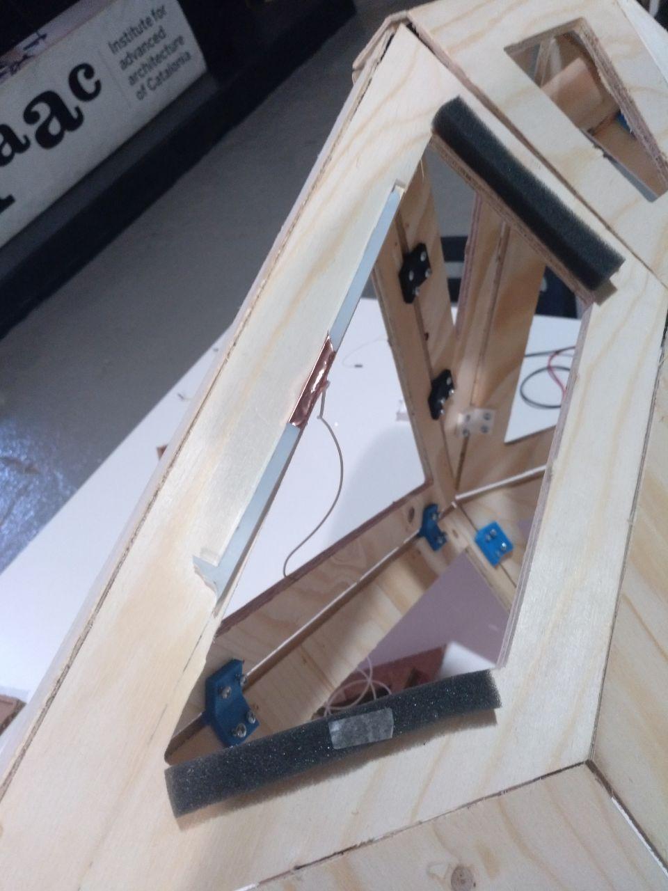
And put some acrylic that I found of 5mm with coper in the other side.
I connected it to the board and… it worked. I could bright up an LED or not if I touched it. Yay!
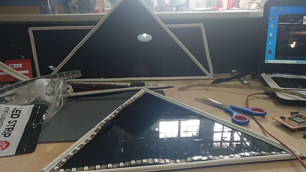
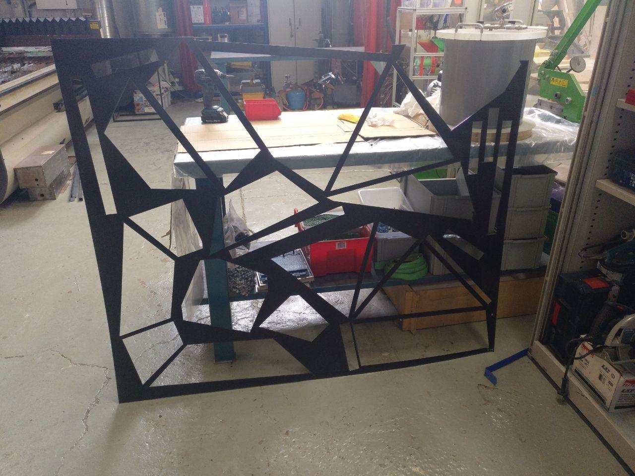
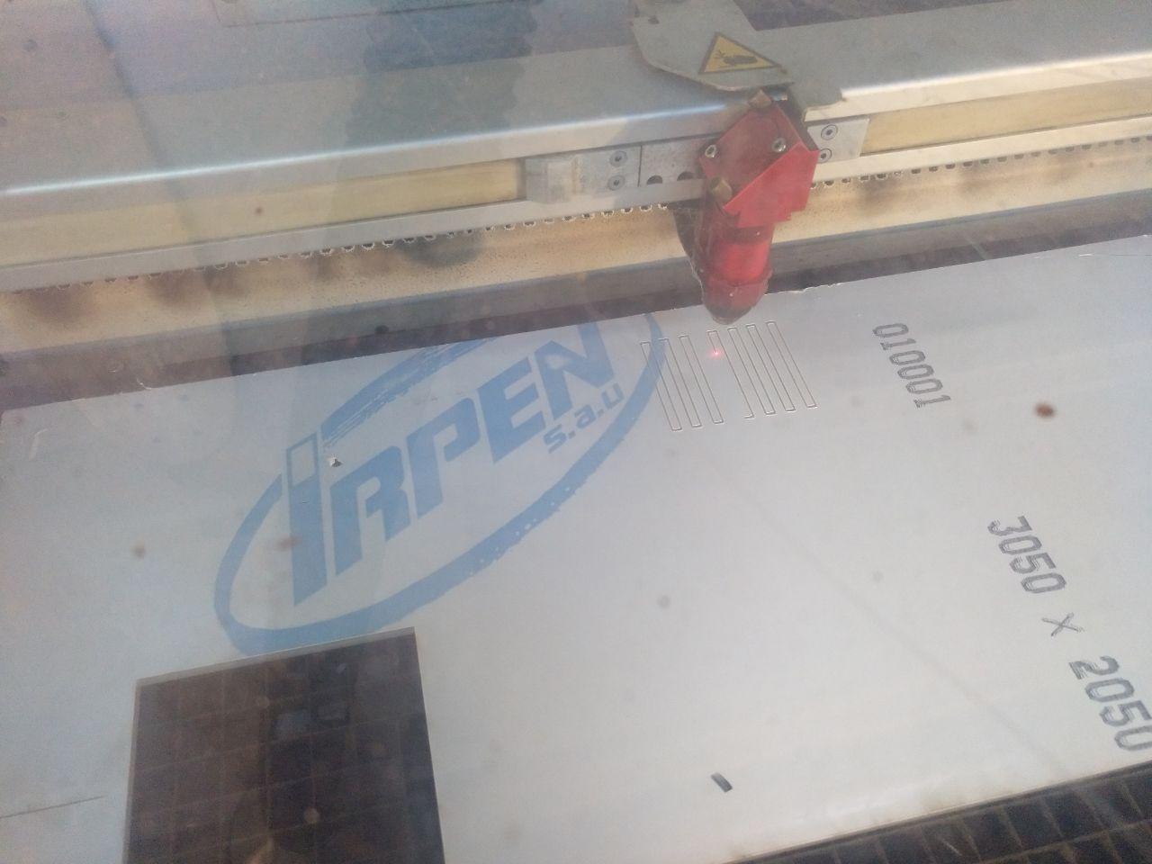
Laser cut. The big dark vinyl.
Now we’re on track. We have the frame but we need the faces! So I checked where I could get some black acrylic. And man acrylic is expensive there wasn’t any options that didn’t imply pay less than 100 €. But it’s going to be worth it.
So GO BIG O GO HOME and I bought a 1,5 x 2,0 m 3mm acrylic for a painful 125 €. But I shouldn’t worry to buy more with no time. The clock is ticking
Incoming deadline 2: Electric Boogaloo
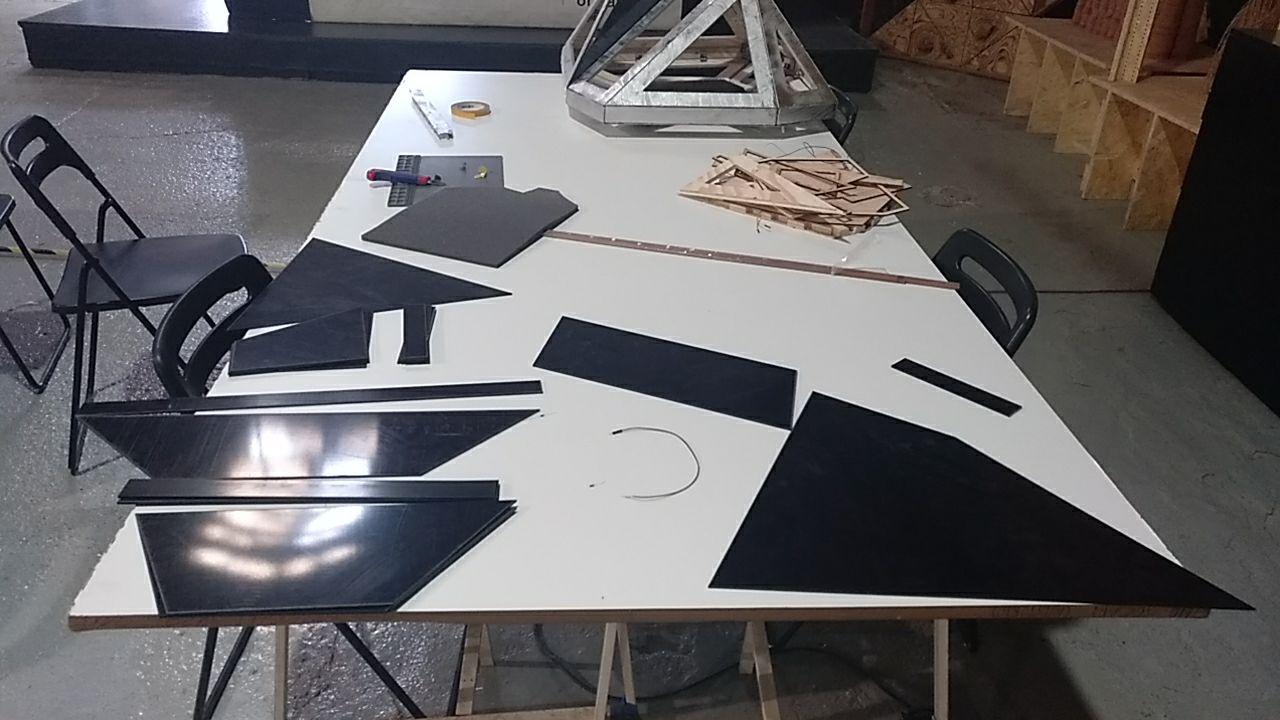
Test the faces
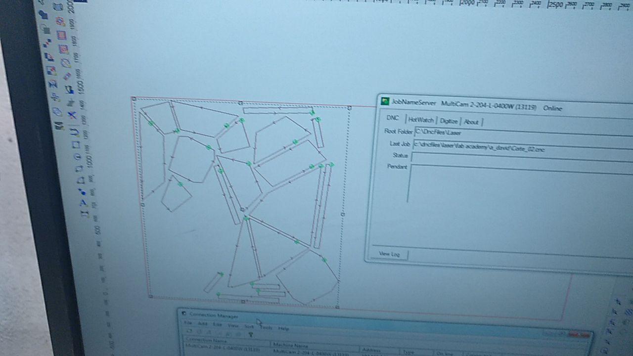
As always, first test, then expand. I don’t want to cut it all at once unless I’m sure that’s worthy.
Now the proces of the Multicam that’s kind of a laser-cnc.
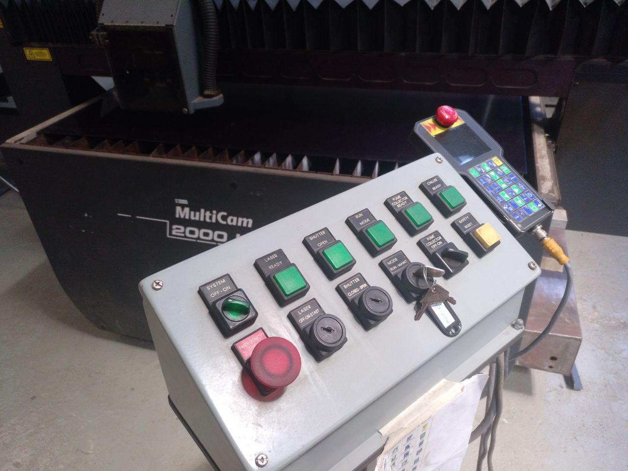
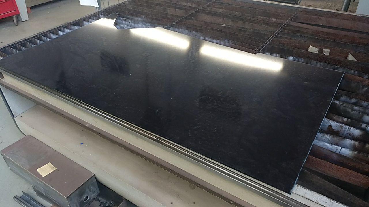
I LOVE the evil genius aesthetic of the control board
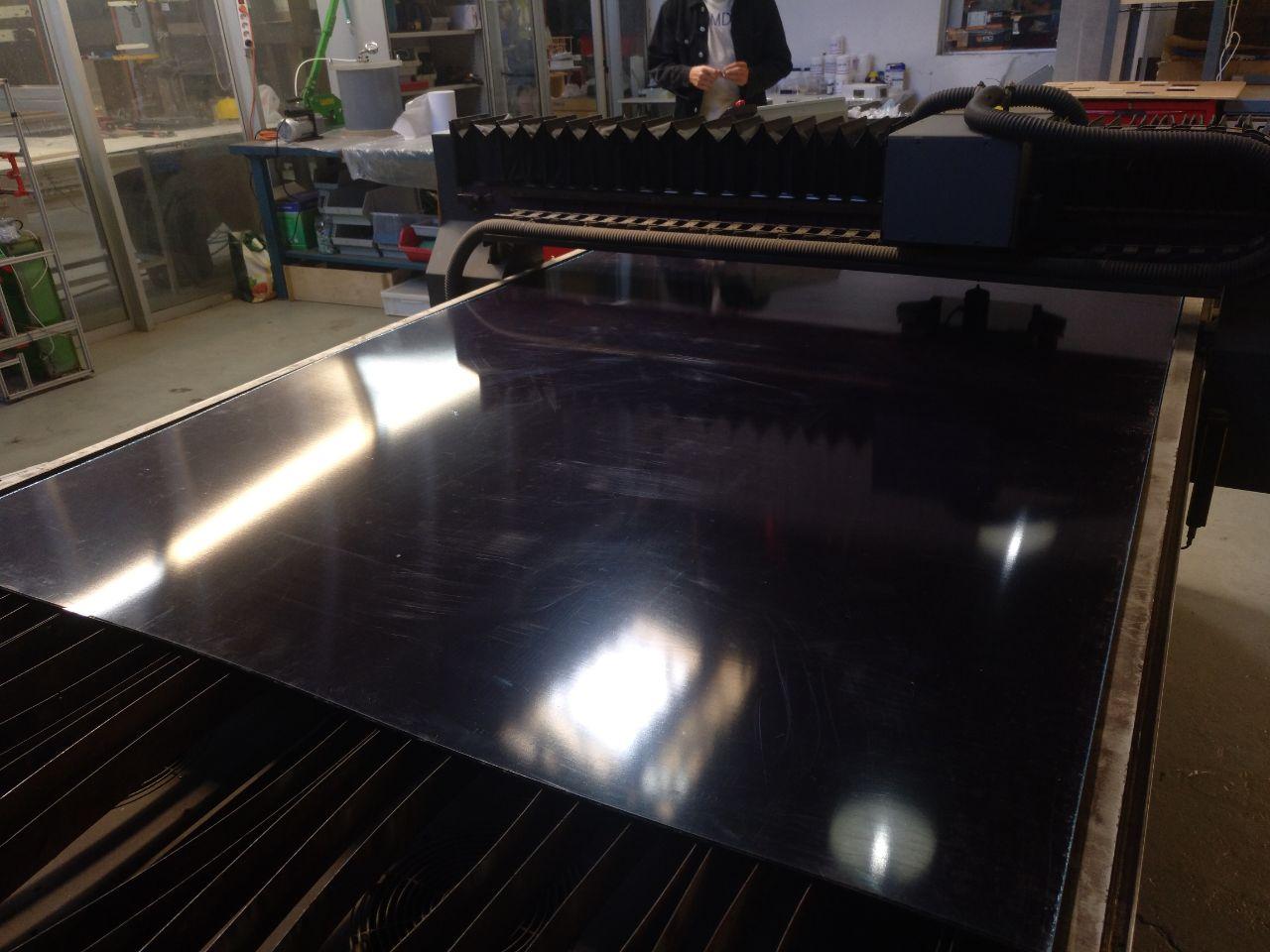
This is the board of 2x1,5 m in the bed of 3x1.5
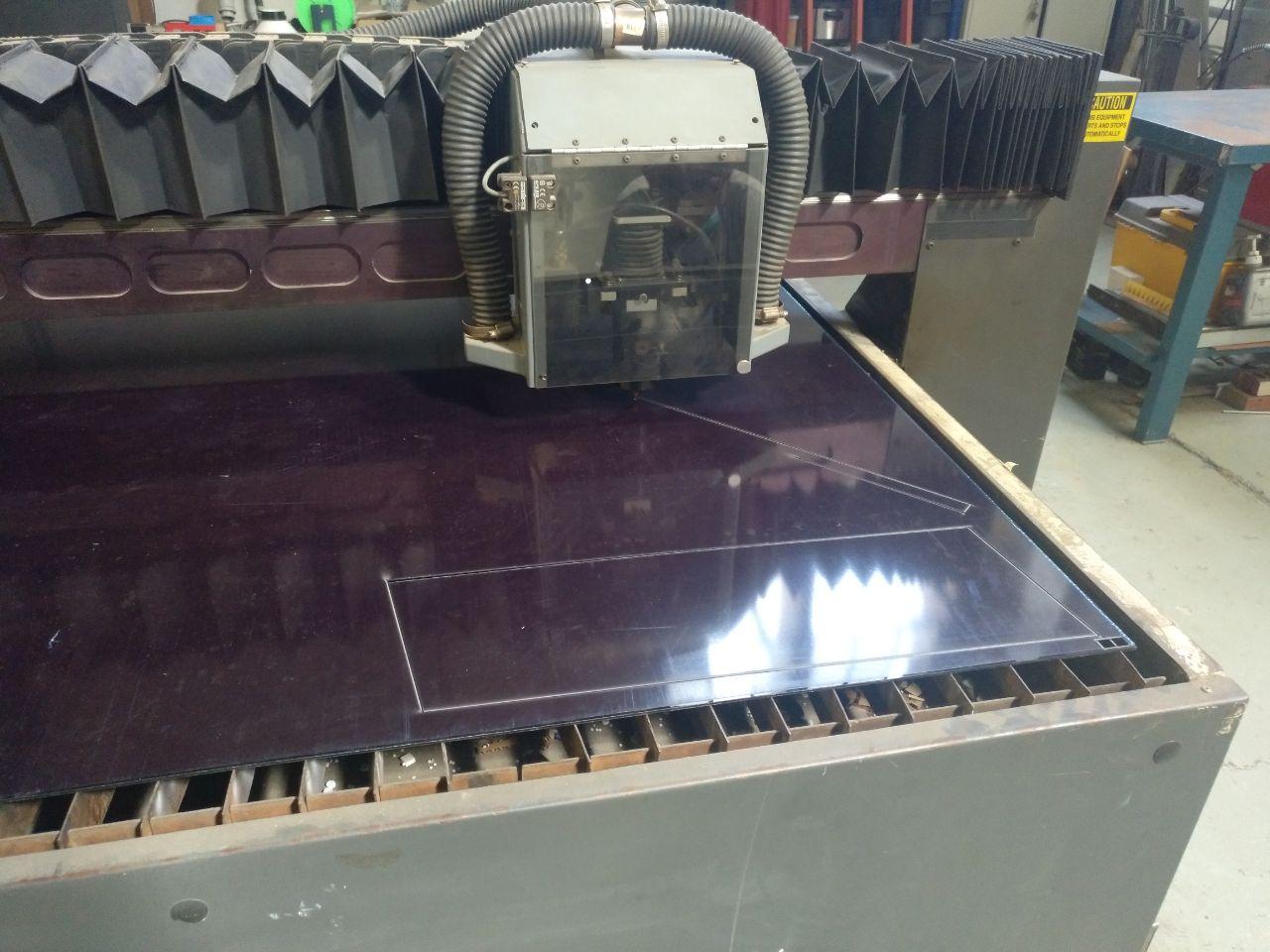
And this is the machine cutting after seeing if the cut its fine with a couple of little sqares on the corner.
Once I have 4 big sides and a couple of medium sized ones I go to…
Mounting the first face
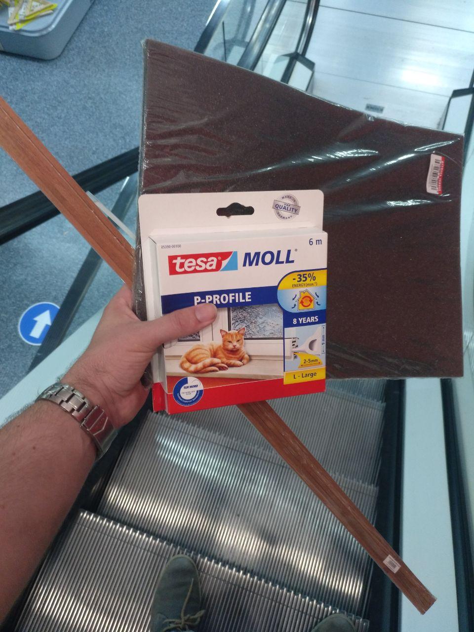
Ok. Now I have it all. Now I can really make the integrated test and make the project work with 1 (one) face. But fist I have to go to servei estacio (a hardware store from Barcelona) and get some materials.
Materials
I bought this:
-
More polyurethane. I didn’t use all of that A3 sheet.
-
P-profile for isolating windows. (7 €/6m) I ended needing another box but for this was fine.
-
Wood 5x5mm squared sticks
I didn’t need the wood in the end (because there wer plenty of transparent acrylic to lasercut). The polyurethane foam extra that I’d need and some isolation material to hide the LED. I’d prefer them to be black but white was also elegant.
Mounting
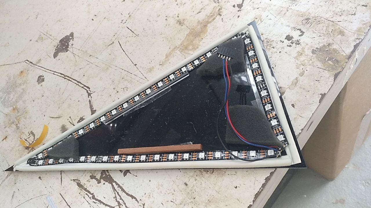
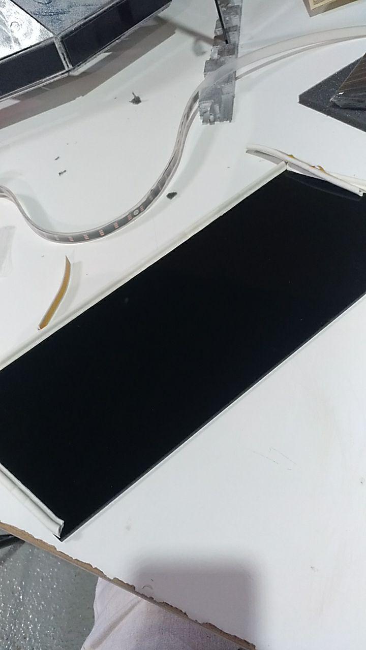
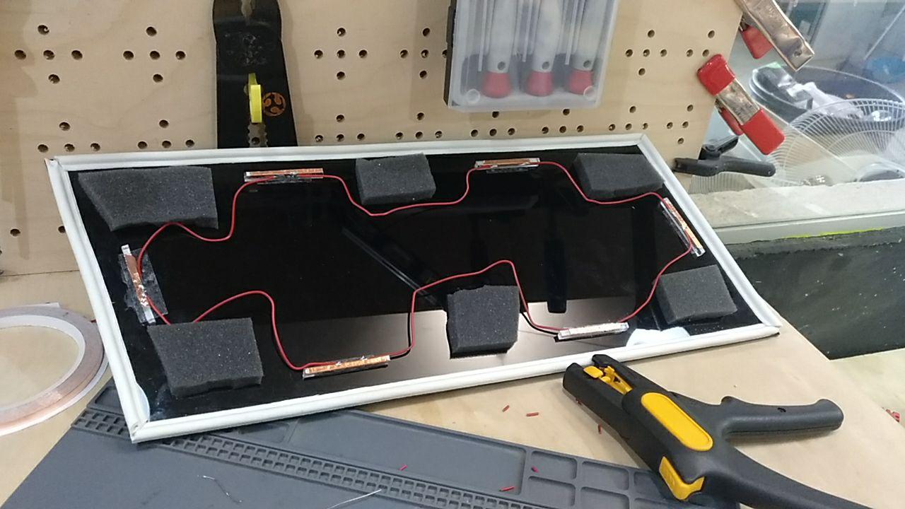
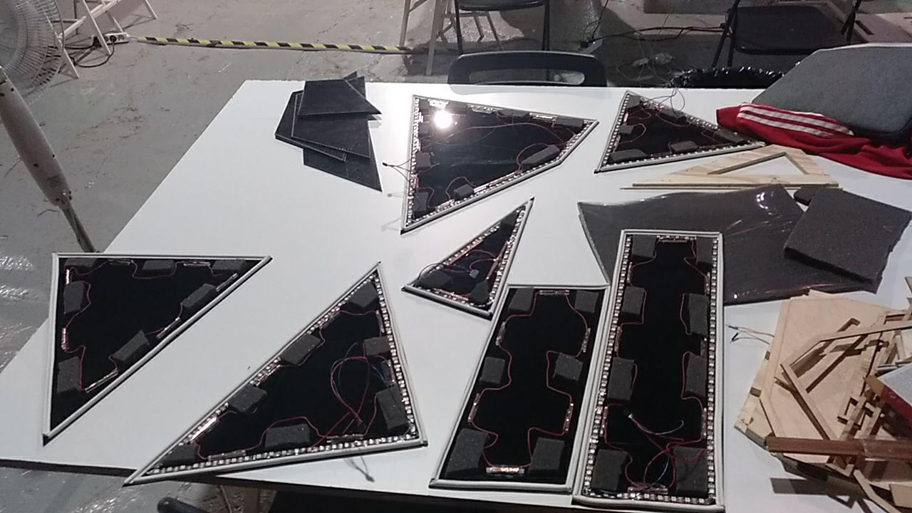
And now the process of mounting one of the faces. The smaller one.
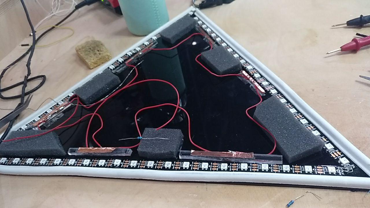
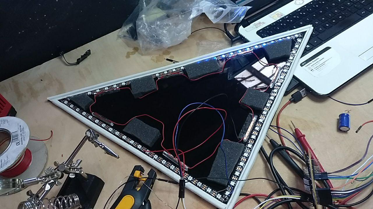
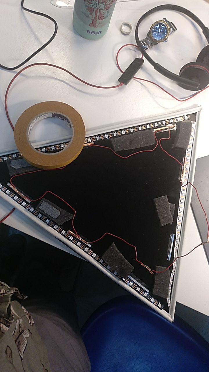
So first the isolation tape around (it came with the adhesive so cool), with some trims.
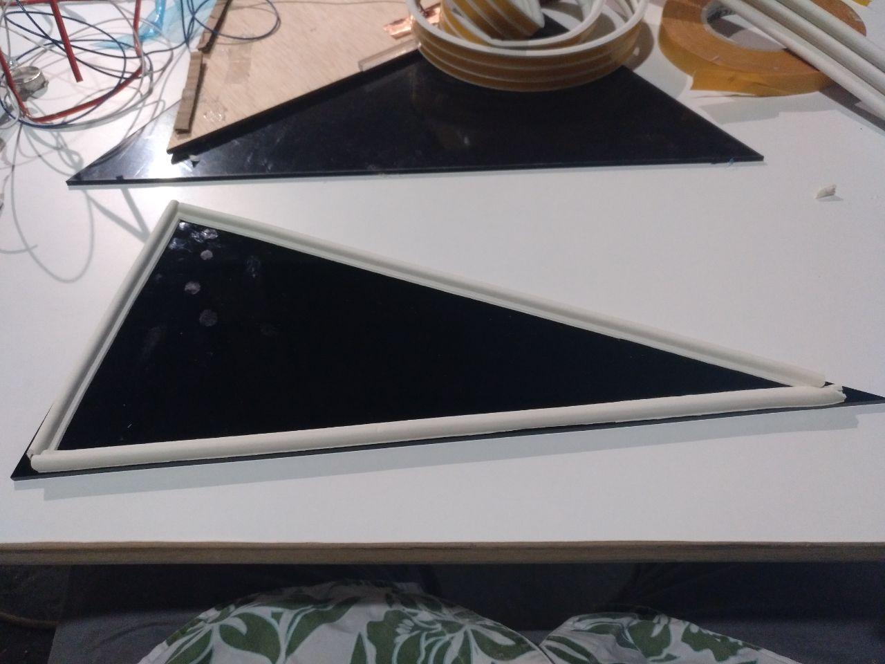
black and white triangle
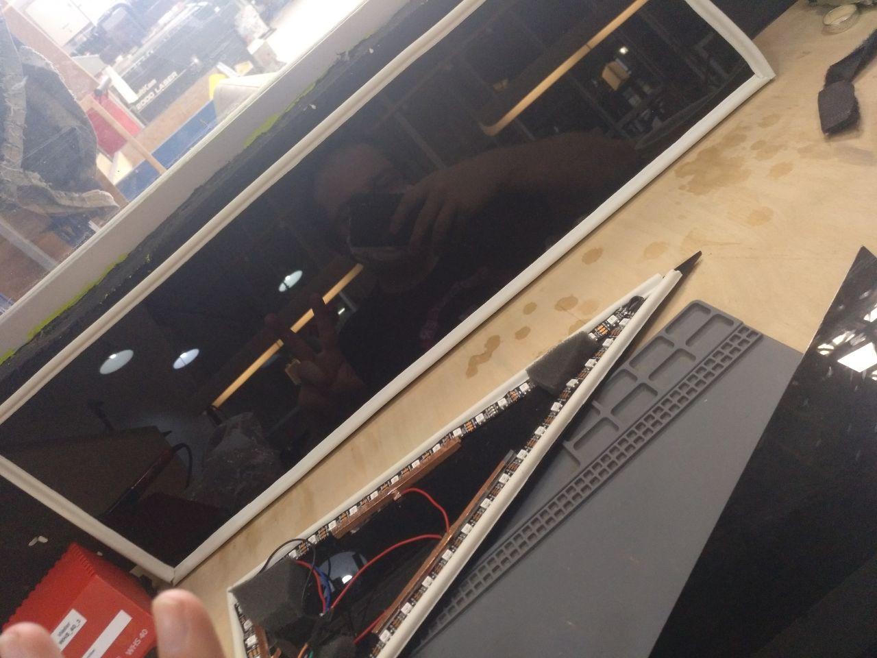
Then I set the addressable LEDs (44). I had to cut them in 3 and now stick them with double side tape.
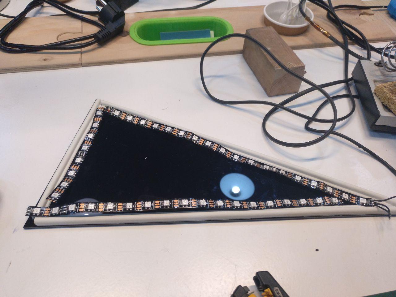
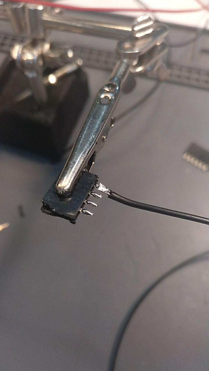
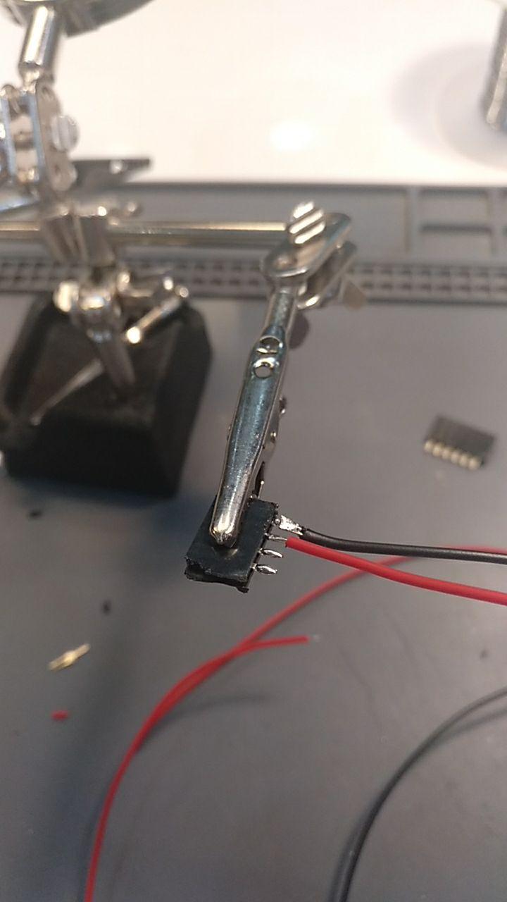
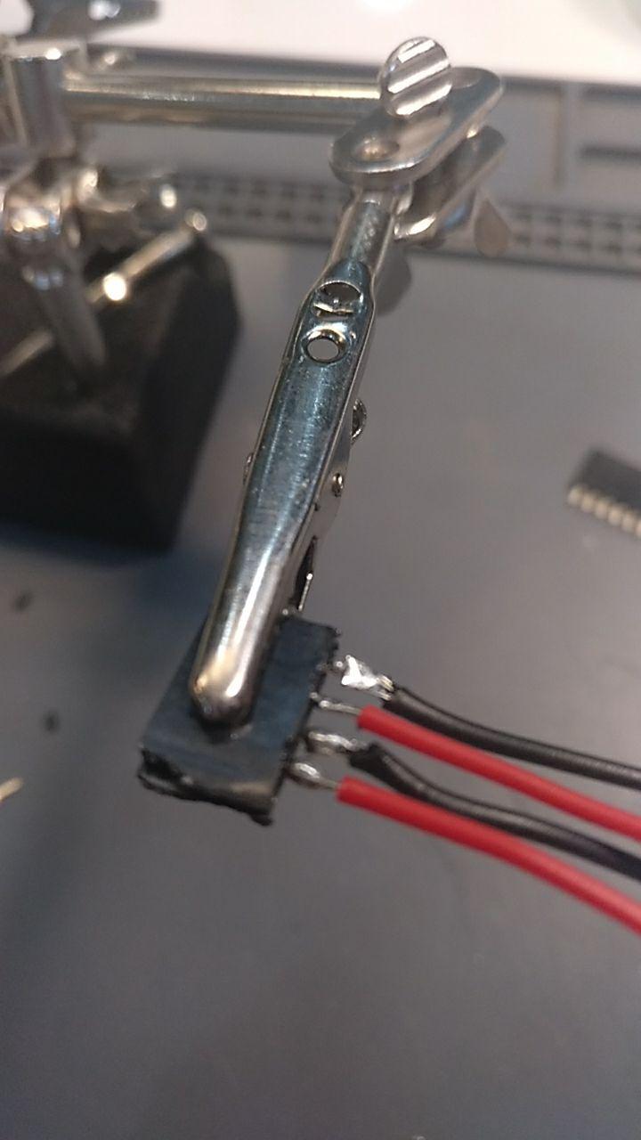
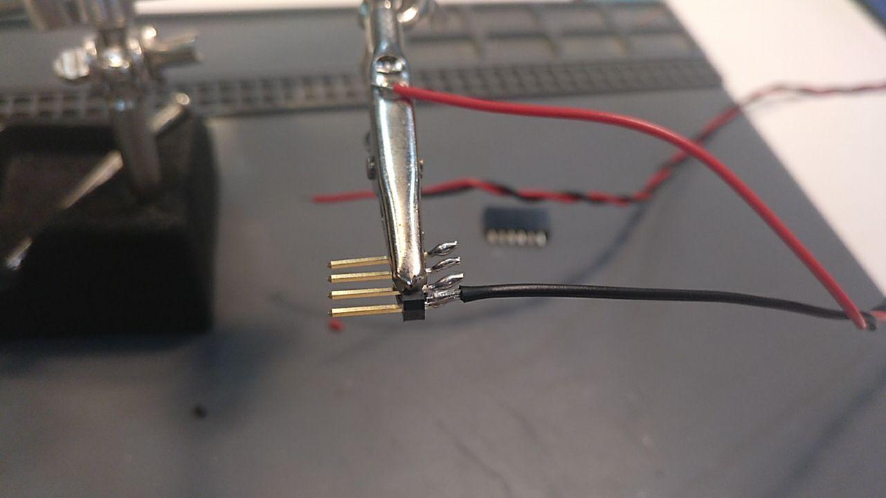
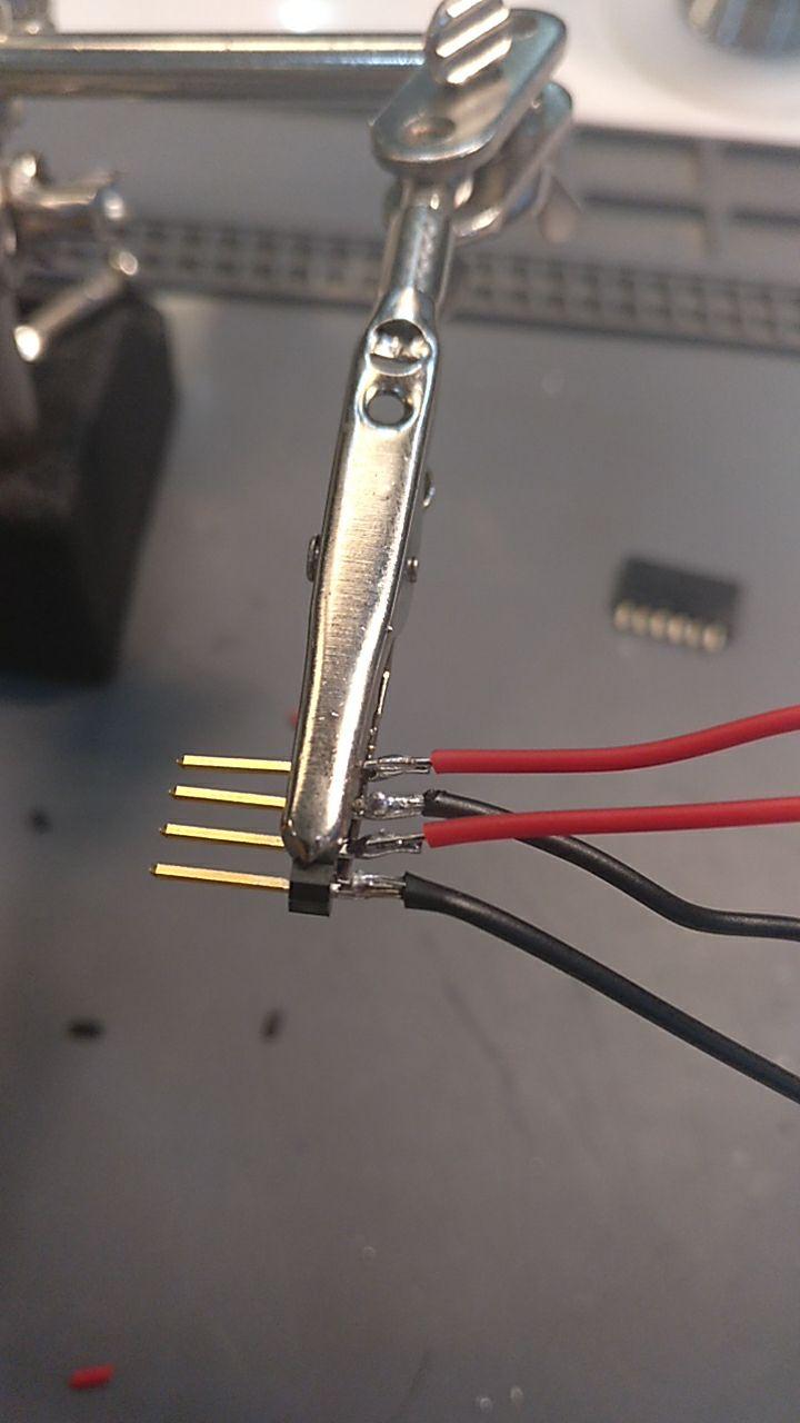
But before I need to connect them. Since it was my first conetcion Y soldiered it as I could with some cable and soldiering wire.
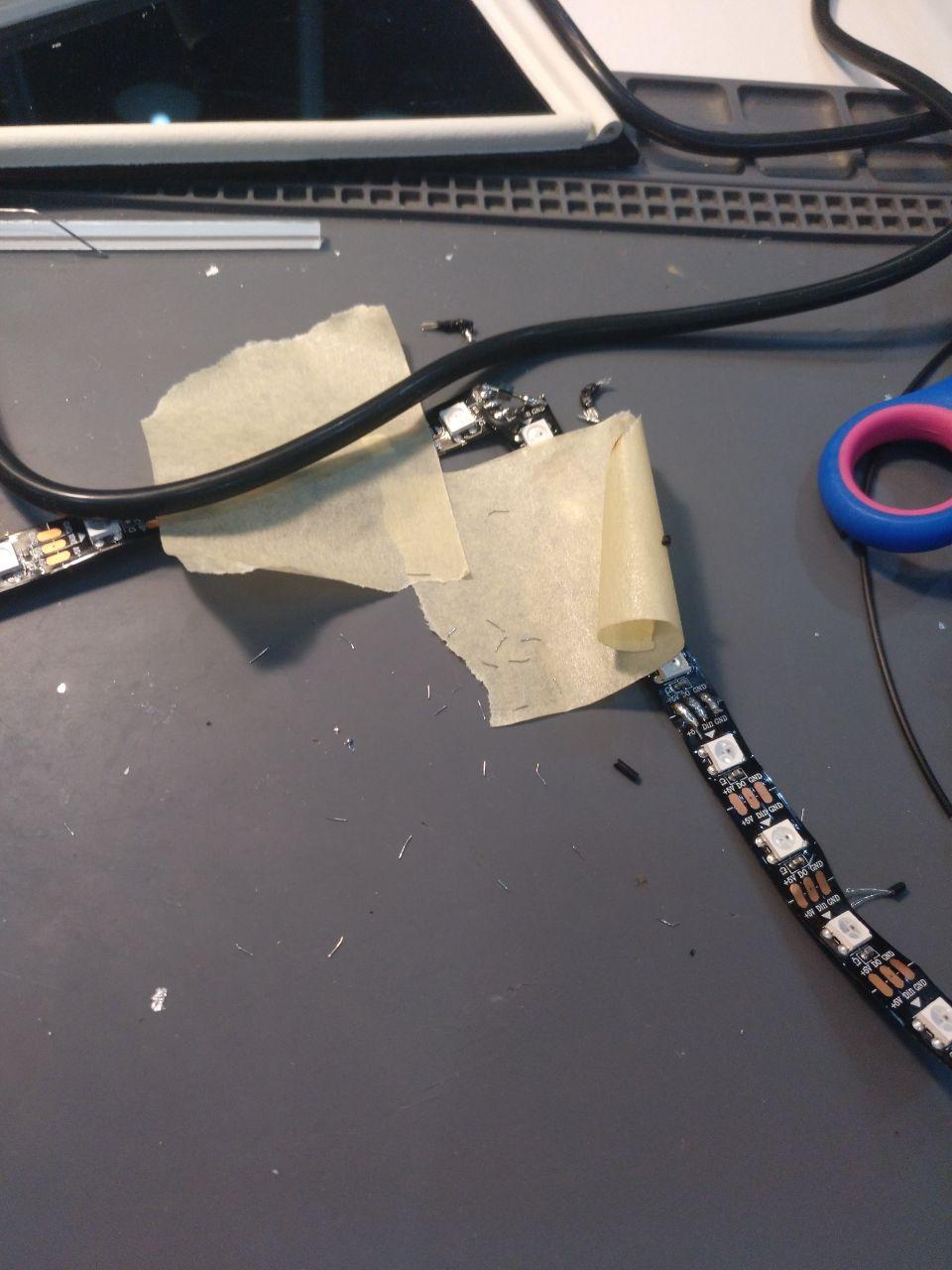
Later I found out a better way to soldier it but for now I had to do this
The three wires mean dark ground, blue signal and red 5V
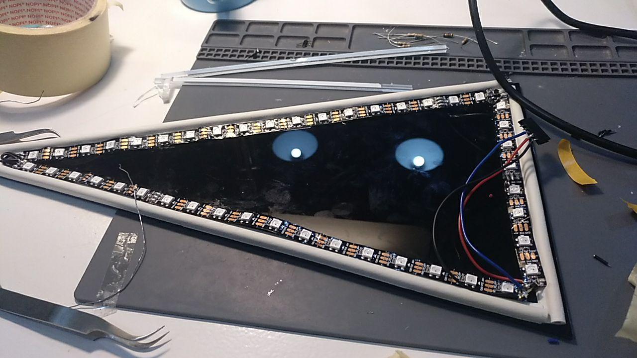
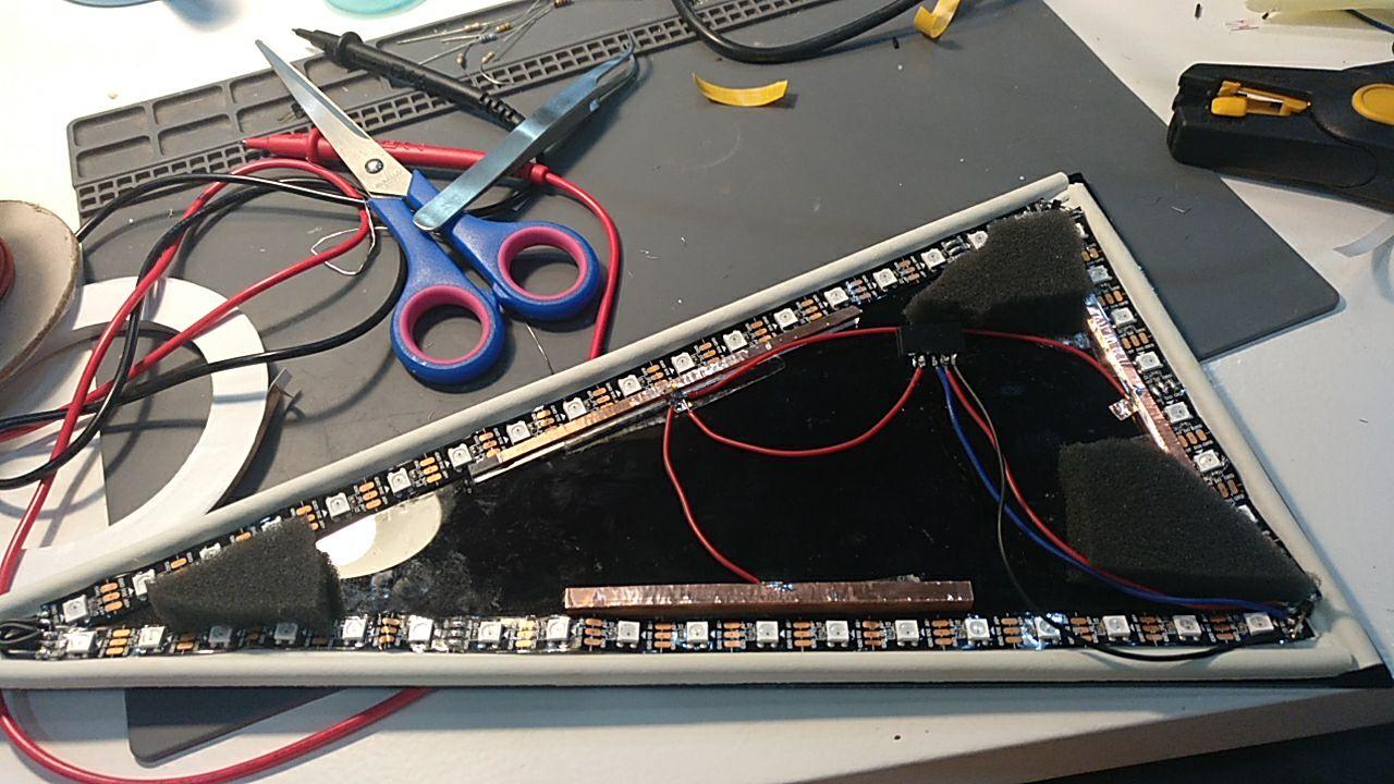
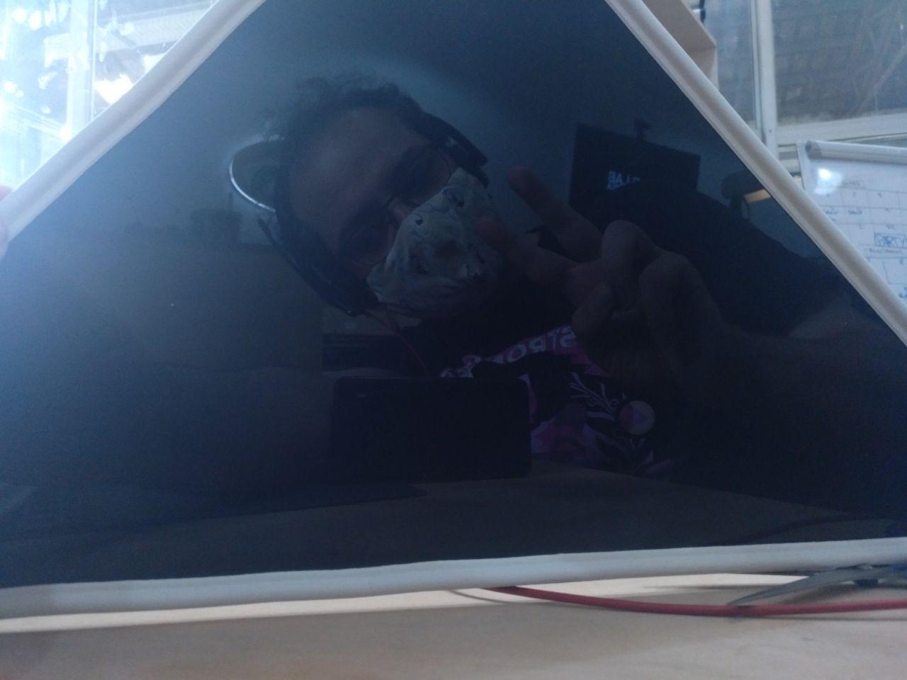
Test the looks
And this is how it looks
Inside
And outside
Adding the button connection
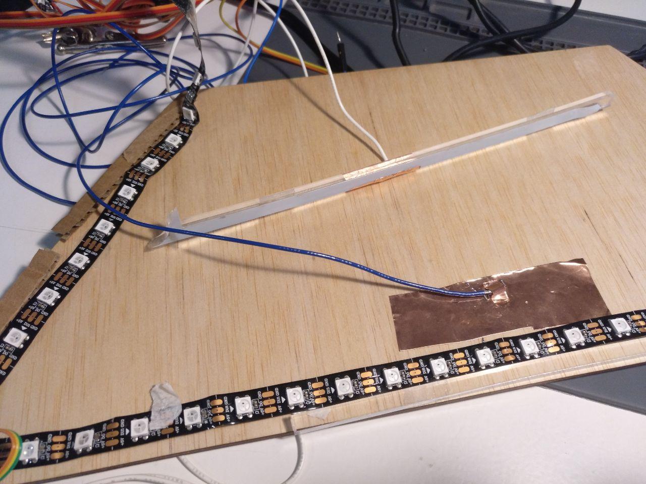
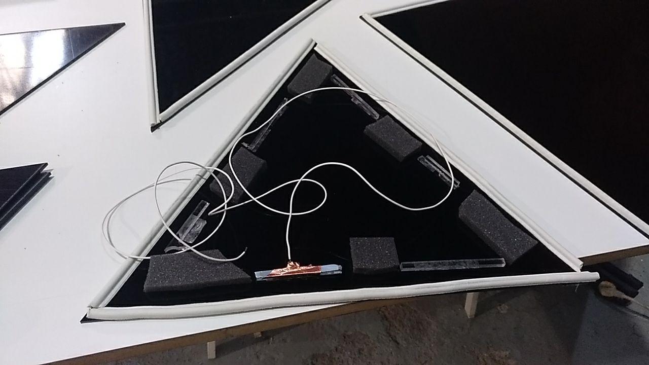
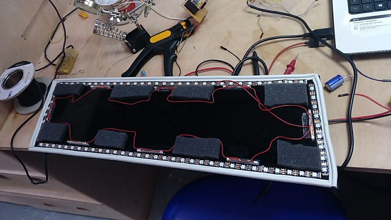
In this first attempt I added chunks of polyurethane foam and the 3 conections one from wood and hte other 5 with transparent acrilic that was at hand.
While using the copper tape I cut myself. Wasnt’ very bad. But I needed to focus better and be more careful.
ouch
Finally I used copper tape of 5mm wide that was more accesible and it was more convenient for this job. I used also red wire to connect it all and connect it to the female connector.
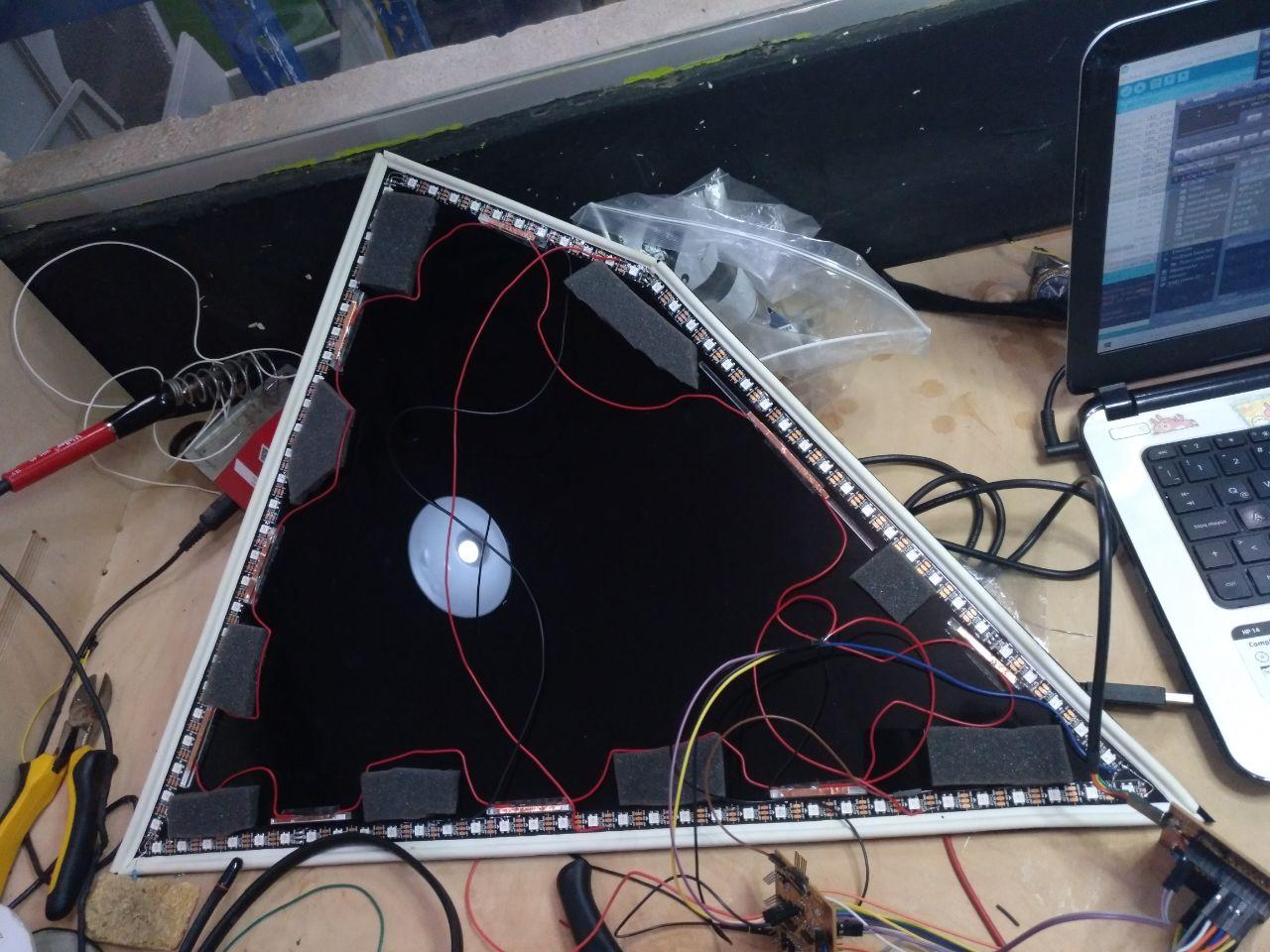
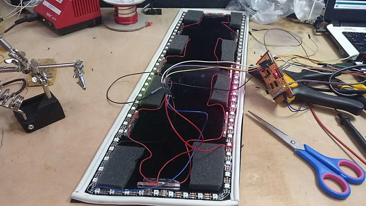
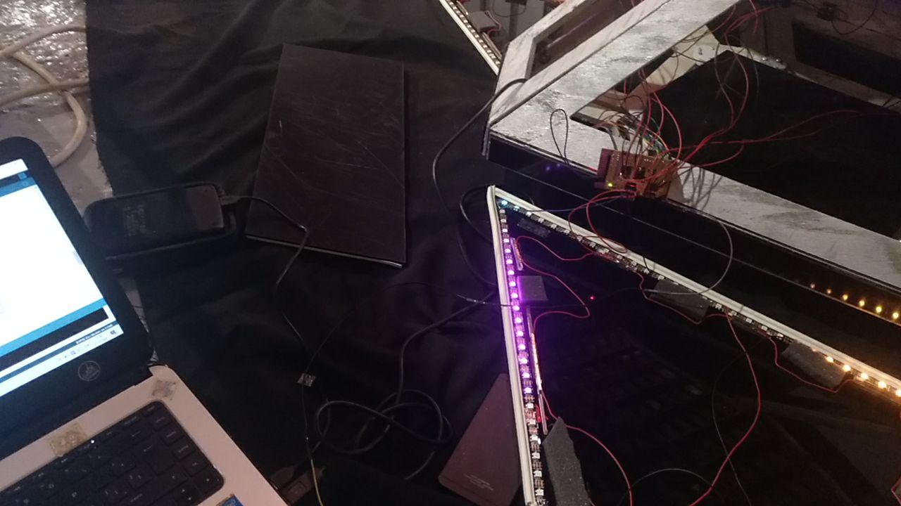
Test with light and button the face
And this was the result!
From the exterior one cool thing is that the friction from the foam was enough to let the face sit without any more strings. That was cool. Even if I finally added any other support
And when I connected it it worked nicely. At this time I didn’t have yet the shield to connect the faces and I only used my Barduino as it is.
CNC-cutting Correcting a couple of faces
Before painting I noticed that were a couple of odd faces. One of them, on the top I think it was recieving all the tolerances from the joints. So I added a couple of mm.
You can see the too much space between the center and the right faces
The other one was very strange. I guess that it was that I moved a dot in Rhino and it went through all the offsets because it was just weird
the old weird piece and the new one
Luckily now I have more speed mounting and preparing the CNC files so it was easy to do from a spare part that I found in the lab.
Pieces cut with the slaps to be cut
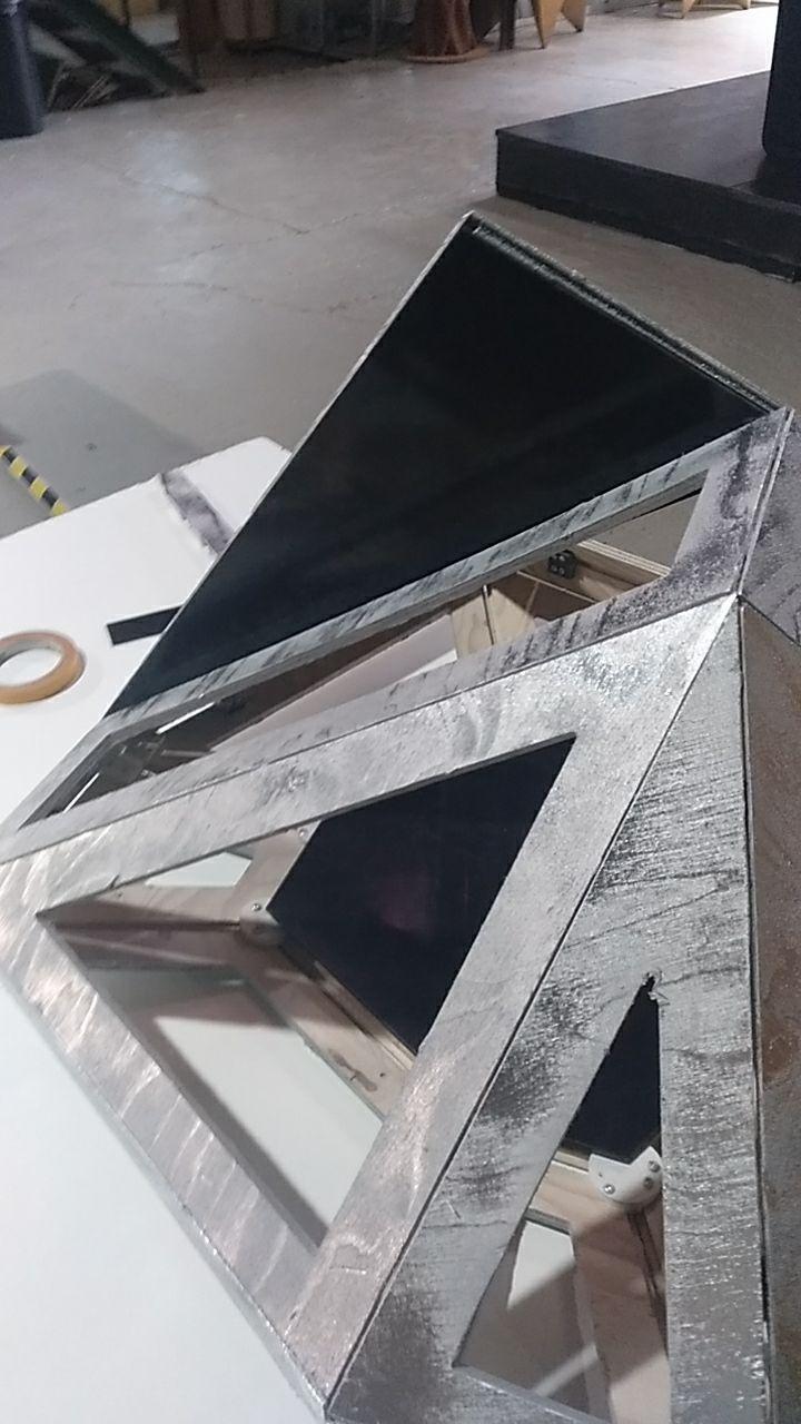
Painting the frame
The frame I wanted to be kind of methalic so it can reflect the light from the LEDs. So I went to a Montana shop and I bought a couple of sprays (one as a base primer) and other for the metallic effect.

17 € between the 2.
I tested first at home with spare wood that I have from tests and the joints.
Test
First base and then the metallic spray. And in some parts just the metallic spray
Shiiiny
What the person from the shop told me was to better affect
-
Short passes. Even going point and point of paint.
-
The paint has 2 times of drying. The first dry of 10 minutes where you can go and make another layer. The second late dry of 48 hours.
Going for it!
So let’s go. First the white base primer and then the metallic effect. I dismounted the base so I could paint it apart from the rest of the pieces.
Here you can see the process:
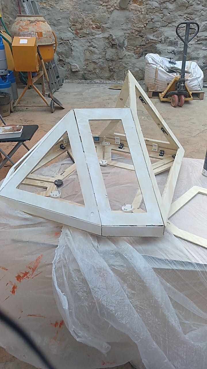
White base
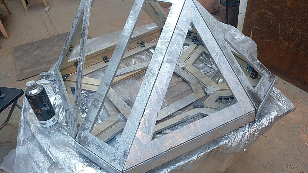
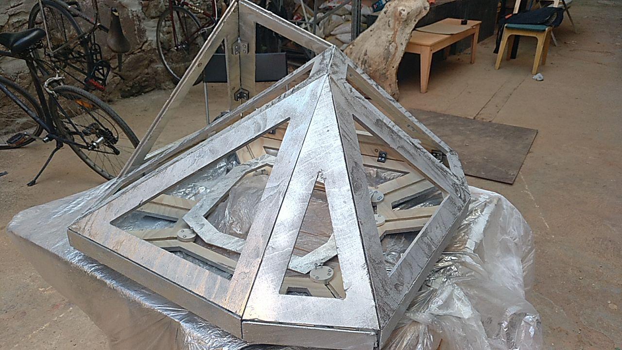
Finished!
detail
Mounting the faces
Now I have the frame painting and drying (48 hours) so I can go and mount the rest of the faces I can make.
I didn’t finish all of them because now I had the time and space to make the other lasercut so I can cut all the faces and forget about it.
Lasercut again
Design of the “off” face
I still have one face that it’s not on the frame or design in the lasercut. So I had to deal with it.
this one
Now that I have the frame mounted I could design the face I needed not diretcly from rhino but what I physically have mounted.
So I took some notes and made this drawing so I can go back to Rhino and draw that shape.
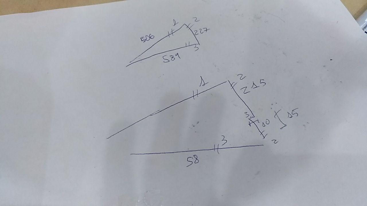
The rest of the faces I already had them in Rhino from the last time so I just have to assemble them.
Process
This time, I didn’t need the nesting program because for me it was very simple to just stack the faces more less together fitting the sheet as much as I could.
it’s kind of foldable (no)
The good part is that I have this sheet of acrilic left that I can use it for anything. Right now I’m thinking of cutting to set some legos on top of it = )
nice!
And I like how broken it’s the other part of the sheet. It’s king of a piece of art wher you can be framed. I’ll try to use it somehow.
Result form the lasercut
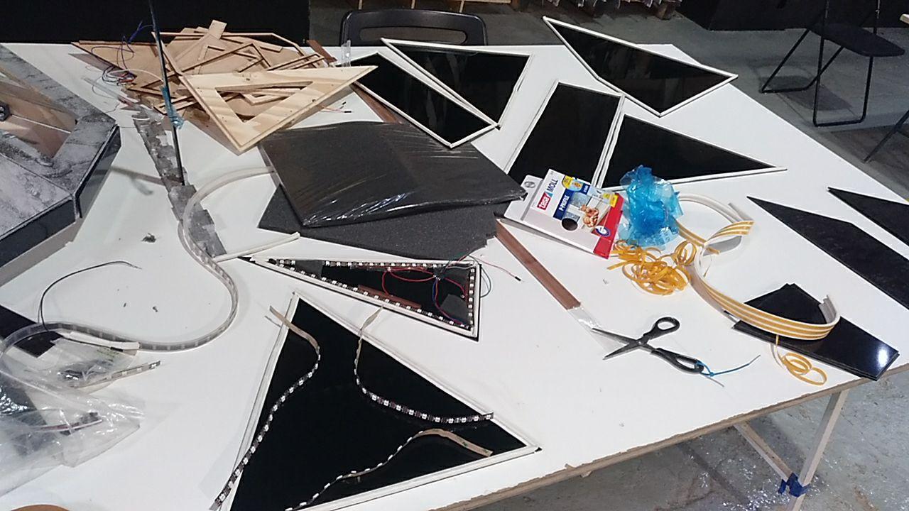
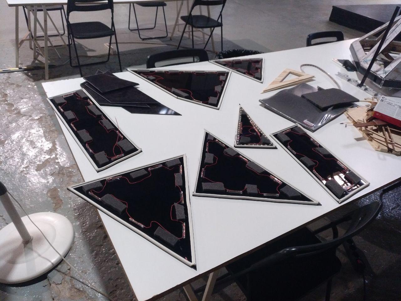
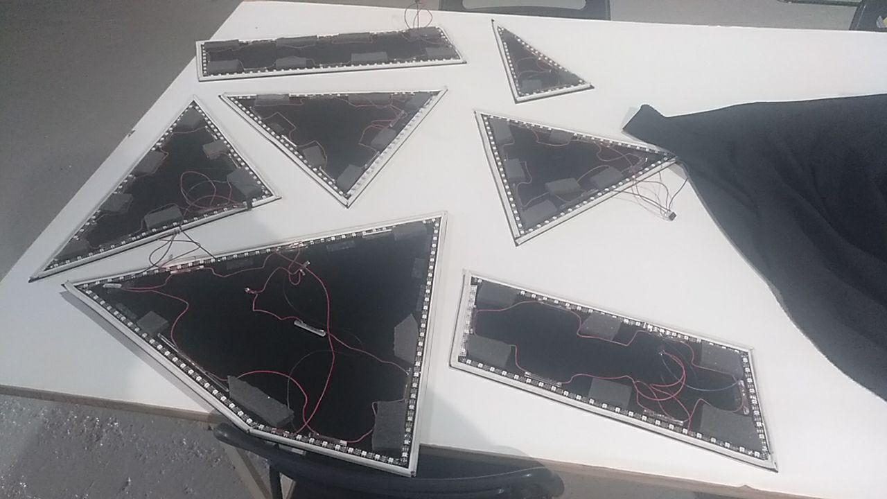
So now I have all the faces ready to be mounted!
All the faces assemble!
Face assembly process
So now all I have to do it’s to assemble all the parts together. Easy right? Let’s have a look of how was that process.
Assembly of the foam
I had here another test where I test the foam if it sticks to the acrylic using double side type. It makes the job but it’s not the best.
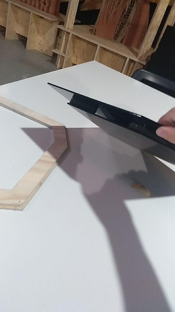
The “off” face mounting
As I mentioned earlier there is a concave face that I wanted to mount (that doesn’t have any button or pushable) that I had to measure from the frame.
So I tested how it behaves and it doesn’t fit bad…
no glue!
But it’s not perfect either so there is a big gap, so it would need to be glued to the frame.
I have to fill in the gap
Testing using silicon
I’m told that gluing acrylic is hard but if the double side tape doesn’t make a bad job. Maybe I can try with hot silicon!
So I tested the acrylic with wood and it worked well!
It’s not a hammer but it can be welded
Not bad
So I used it with the “off” face and it worked!
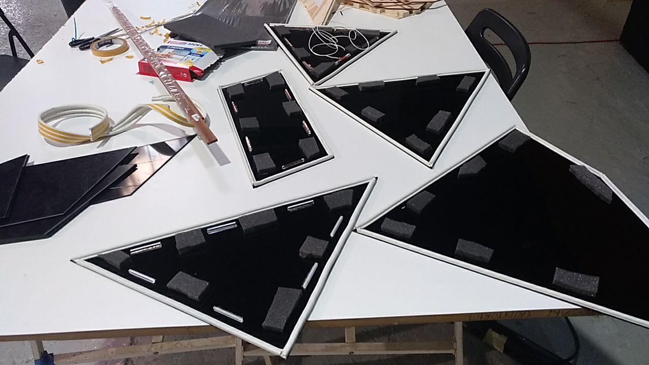
Serialize the assembly process
So now it’s time to go and serialize the work I did for the first face to all the 7.
bip bop
So let’s start with the white edge
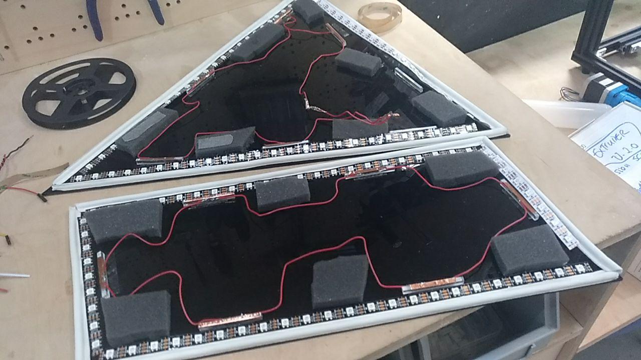
Process of one of the faces
Done!
I added also the foam and I used some acrylics I’ve found on the lab that can be used as the button clickers. (and the one I’ve used for the test face)
that’s why it’s so long that cable
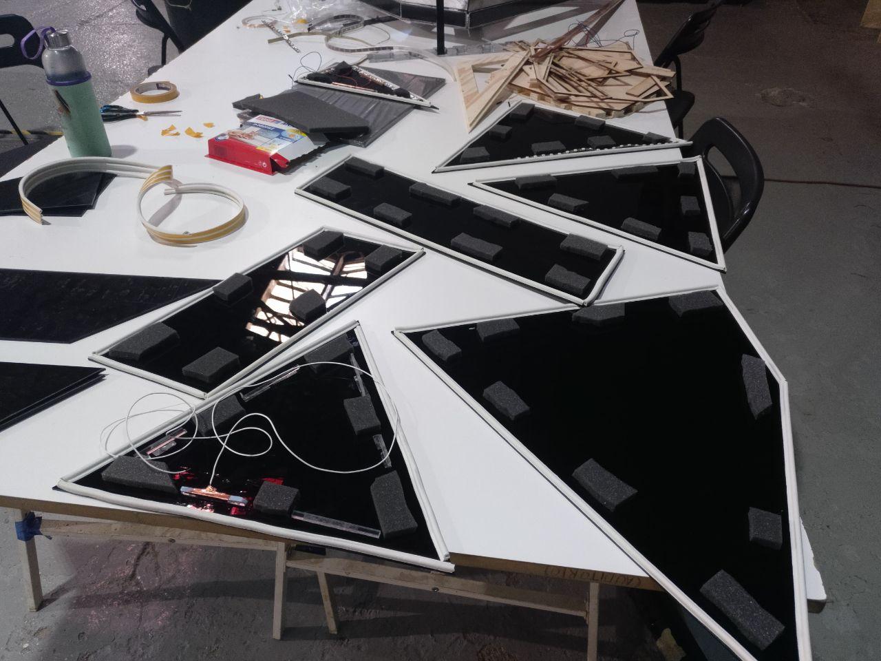
Added the foam!
Assembly of the button sensor with copper
So the foam and the edge was easy but the button it’s another story. First I thought of cutting wood but when I was mounting I found that it was better using acrylic scraps and cut some.
Extra acrilic
So I went to the lasercut and cut some rectangles
as you can see it was an scrap in scrap season next to the project presentation!
Keep mounting
I put those acrylics with double sided tape into the other acrylic. I think I could have used a more specific glue but for this matter this just worked pretty fine.
Process
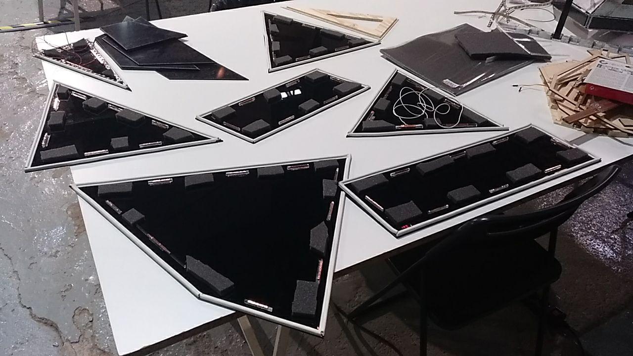
all acrylic set in place in the 7 faces
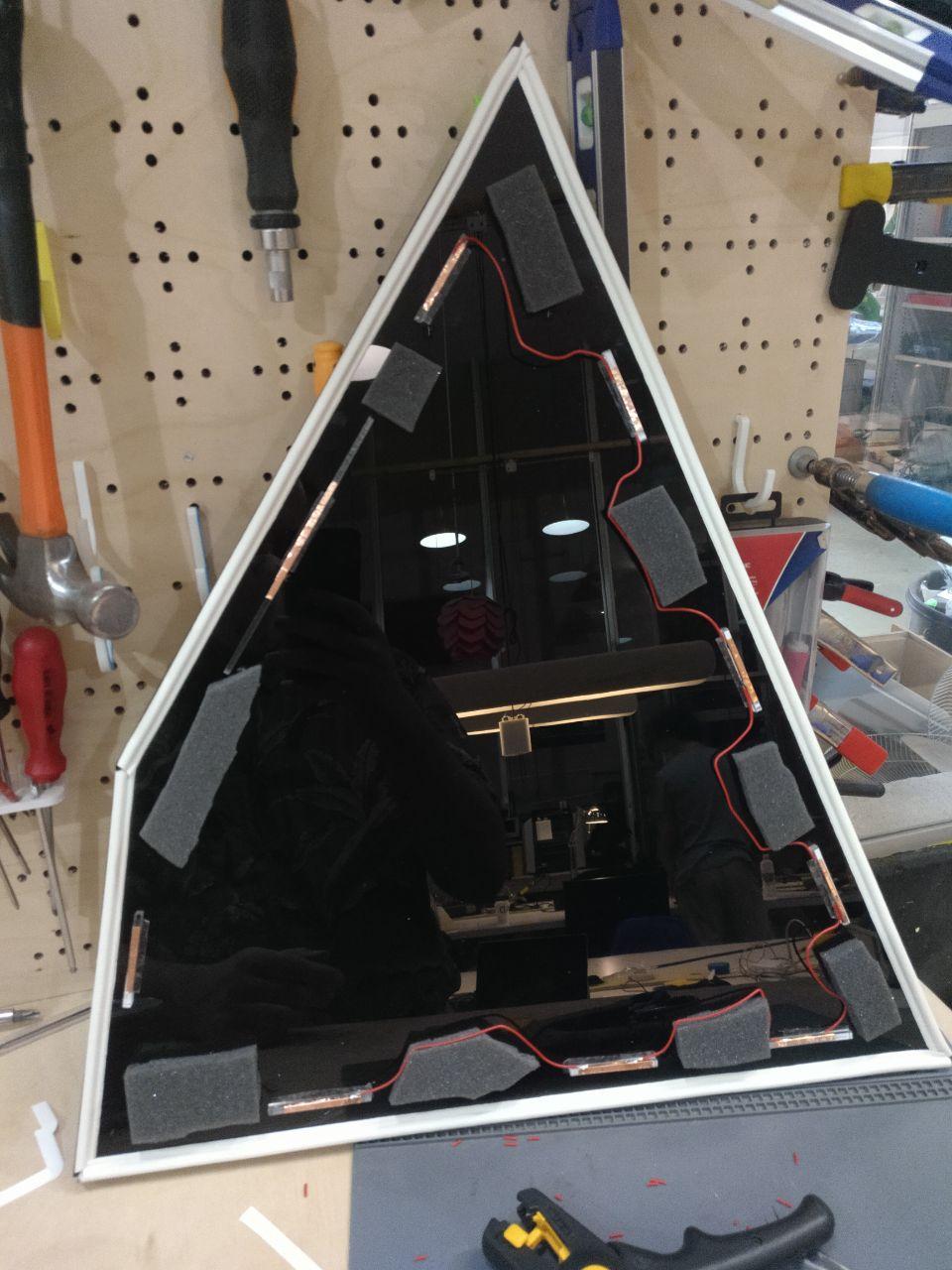
Wiring the button
For the wiring I’d need to put thin coppertape in those acrylics and connect all of them together to make the button. So I soldier each part one by one.
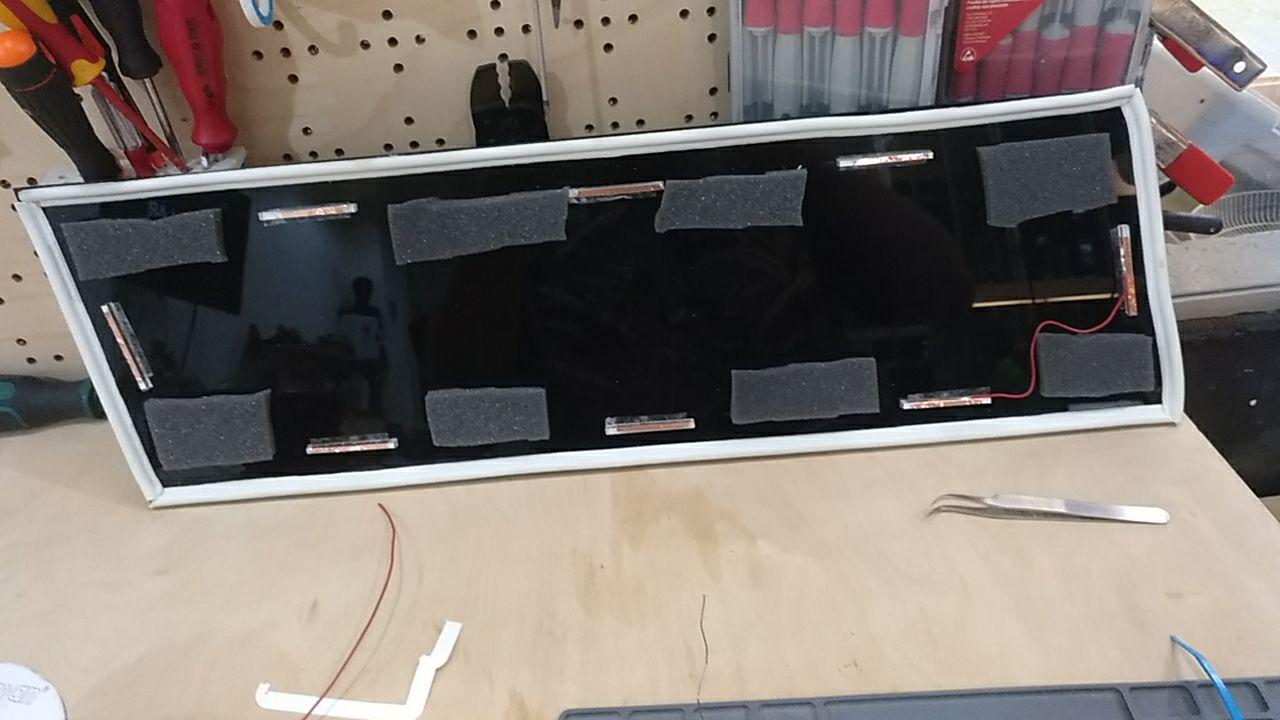
First cable
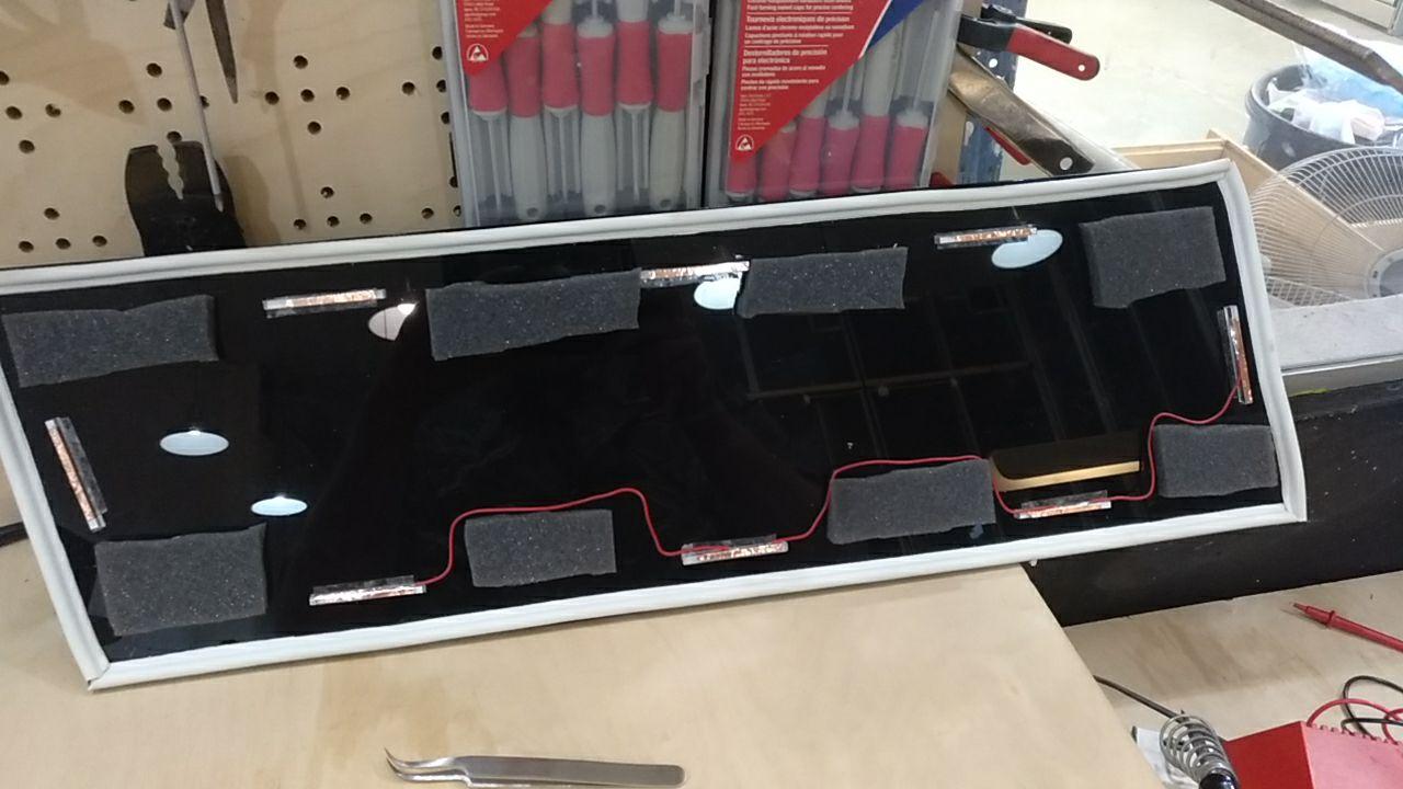
Middle process of the snake
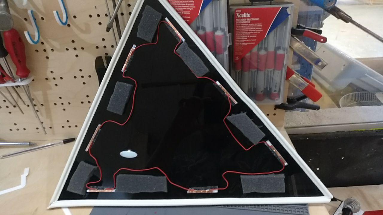
And when I finish the circle, I add another cable to connect in the base to a connector.
the circle is completed
I keep using the multimeter just before closing the circle to check that all the circuit is properly connected. (closing it it’s just to make it work better just in case)
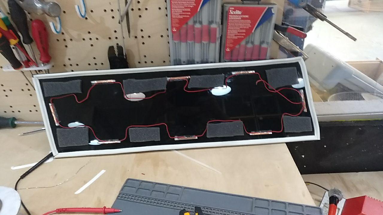
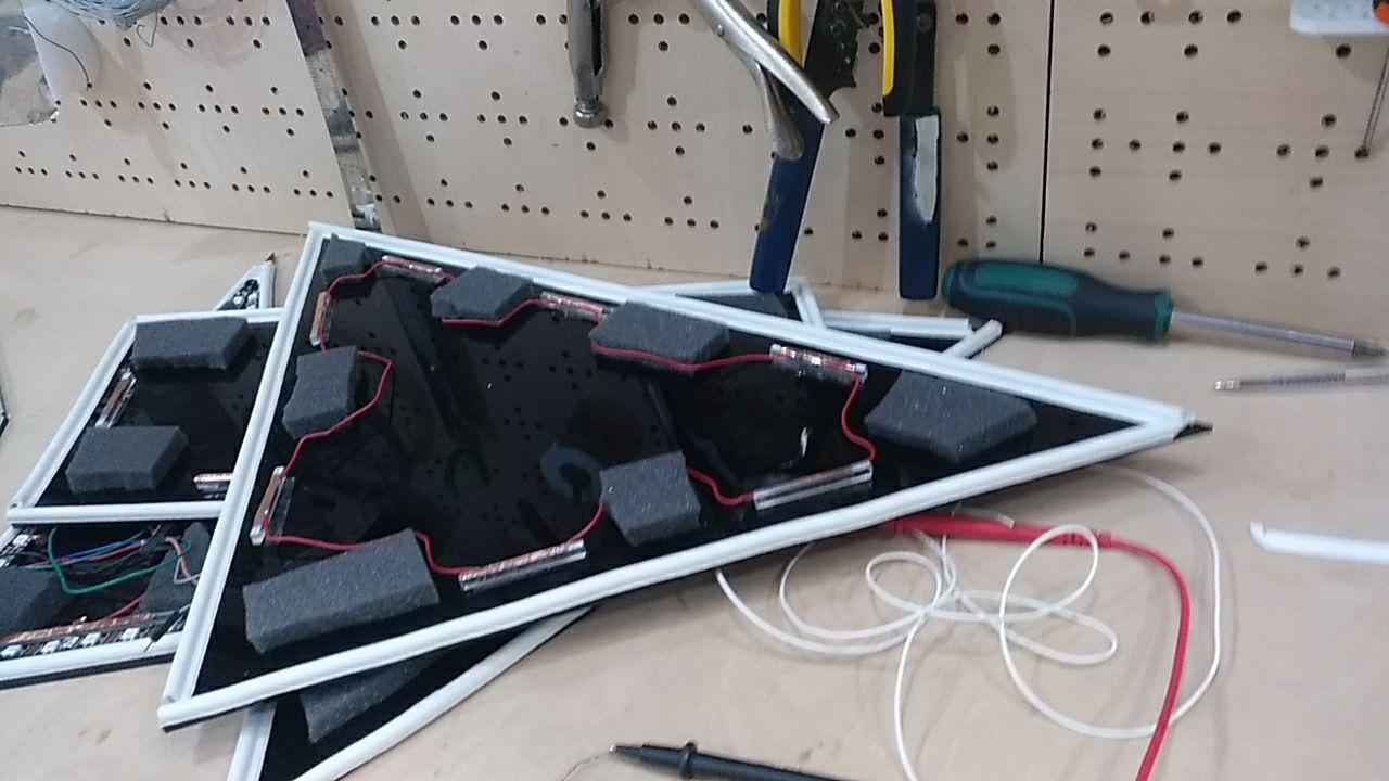
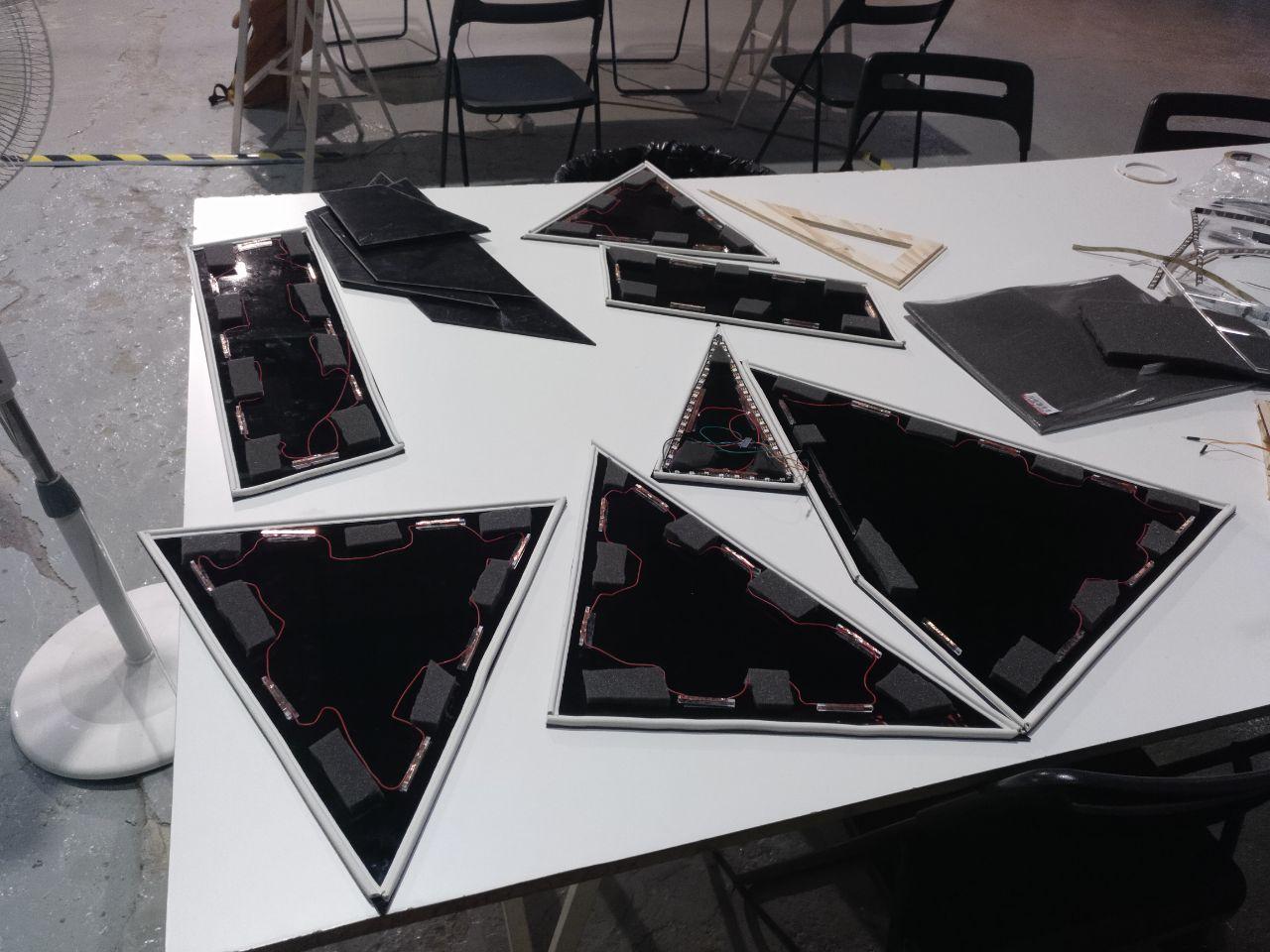
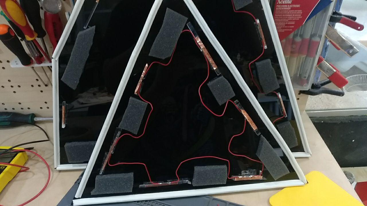
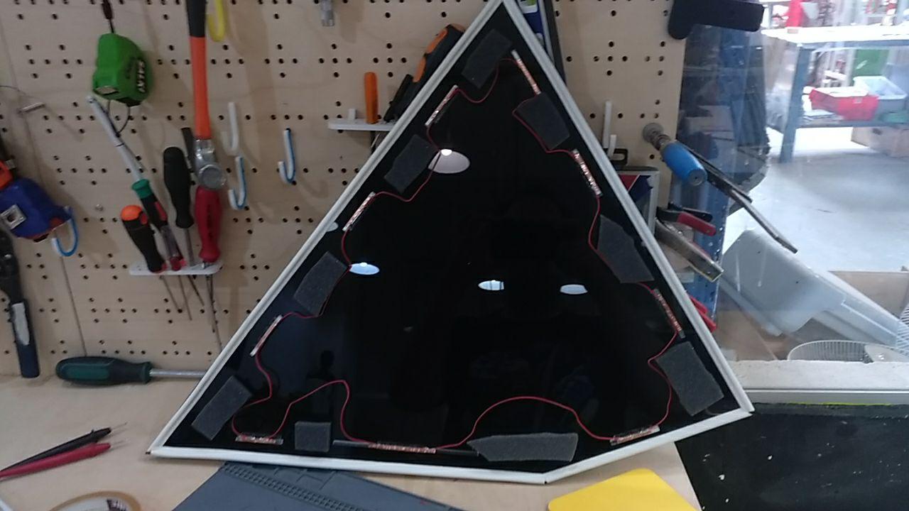
Continuing the process
Here you can see some images of the process of mounting alll that wire into the faces, one by one.
LED mounting
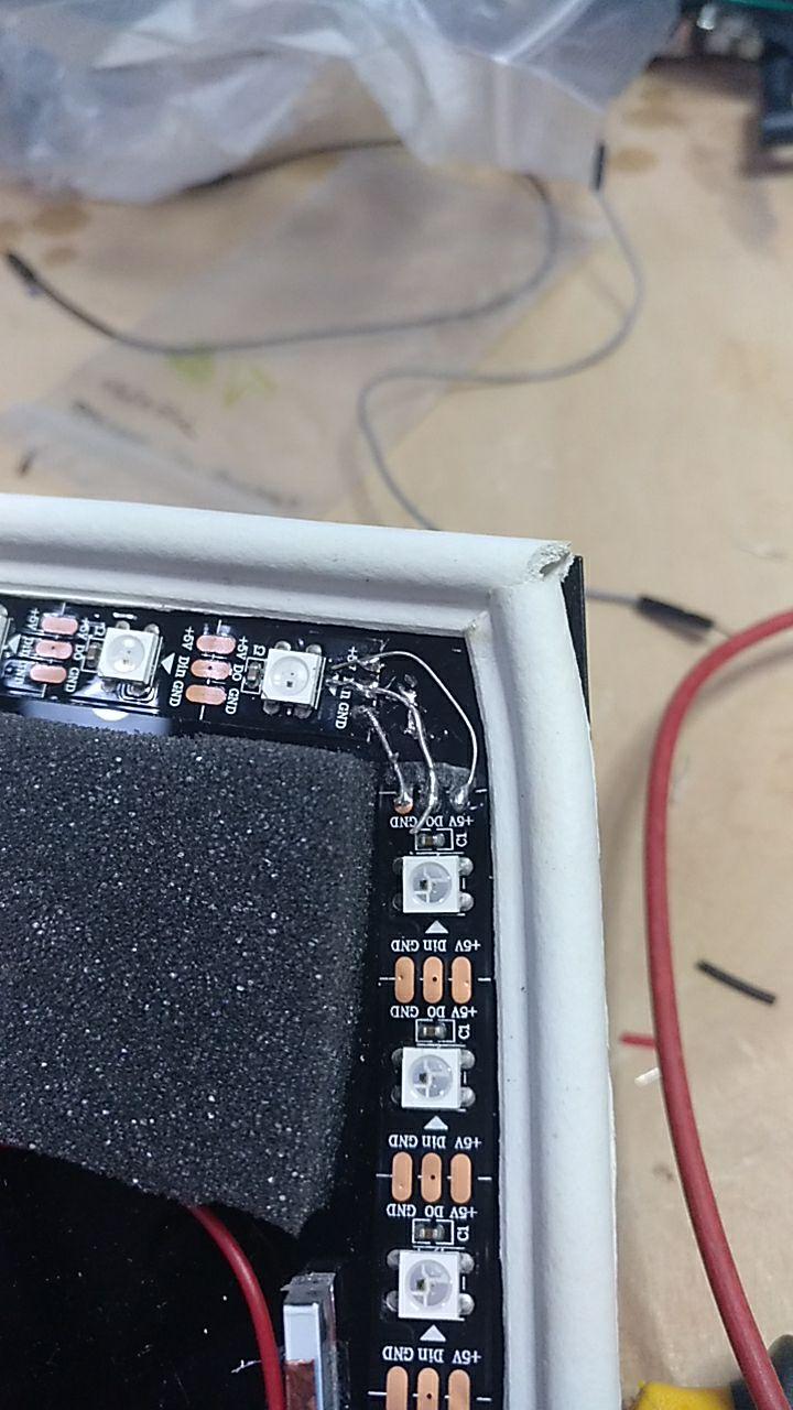
Now I needed to put in place all the addressable LEDs and the wiring.
The Addressable LEDs come with double sided tape so that part is easy but the connection that you need is to connect all the grounds, all the signals and all but one of the corners of the Data signal.
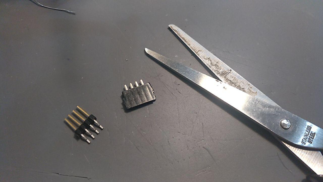
The resistance trick
Here I applied a trick that Eduardo told me to make the connection of these corners and it’s using some cheap resistors legs to soldier them and then cut the resistor. It was much faster this way than peeling cables for these small connections
LED process
Once is set I test if the face works properly using some jumpers into the barduino.
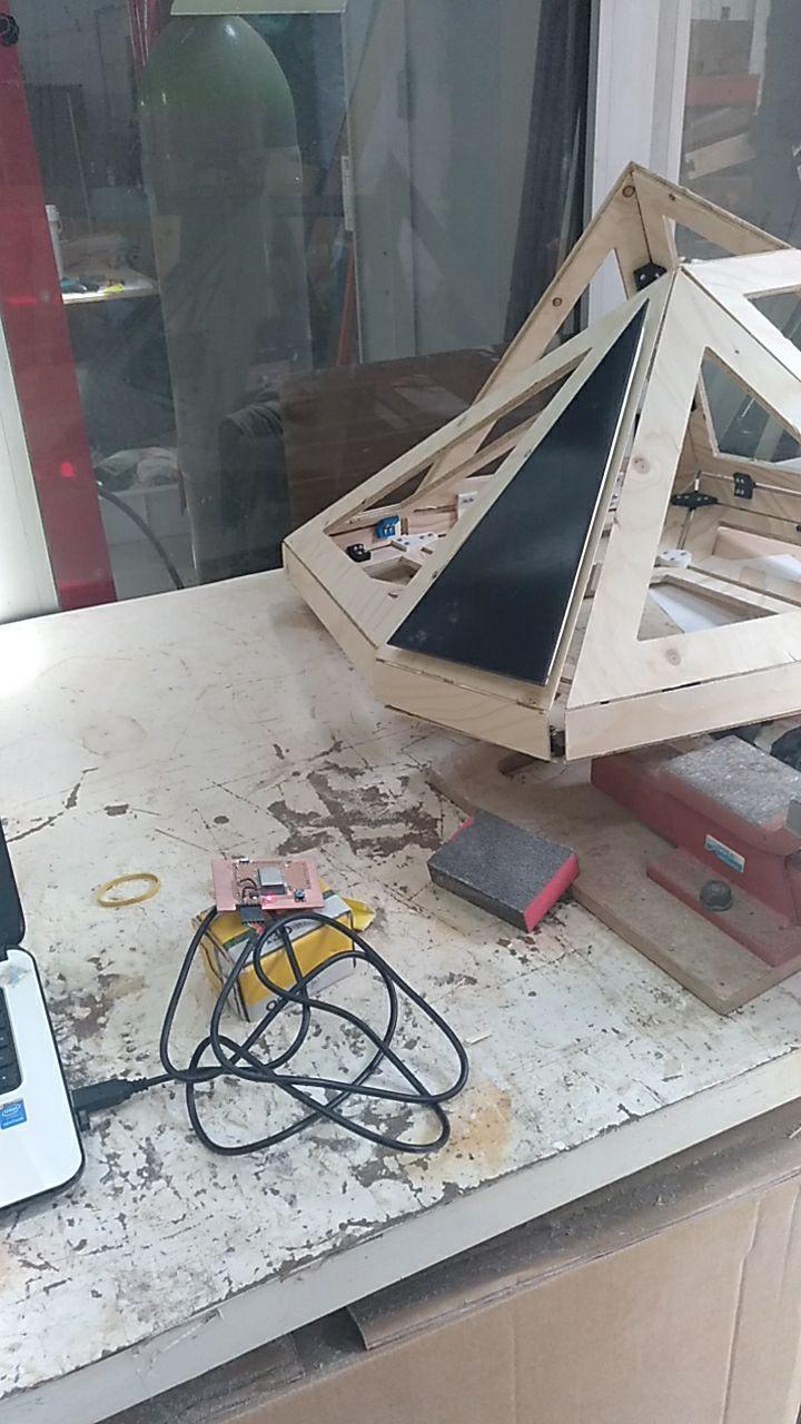
Final mounting and testing
As the days go by, and the day of the presentation gets near I realize that… I don’t have enough time for making all the faces for the day 22nd
(5 faces done out of 7)
So I decide to mount it all together as it is because it holds well.
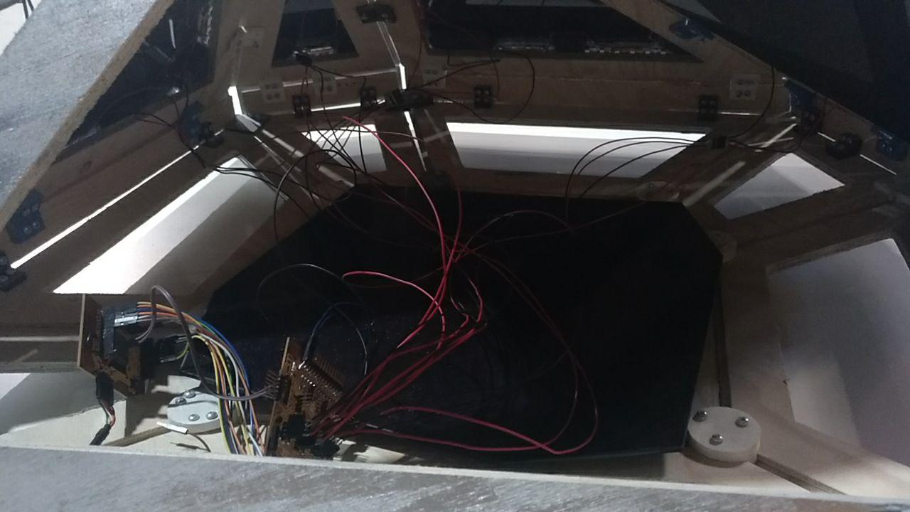
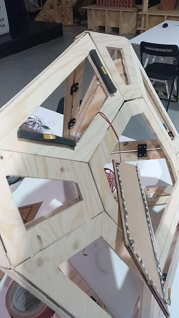
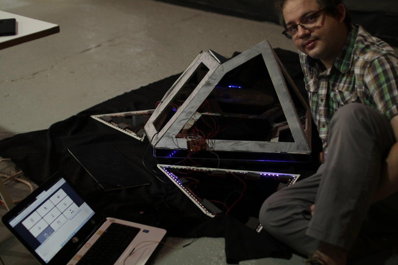
internal wiring
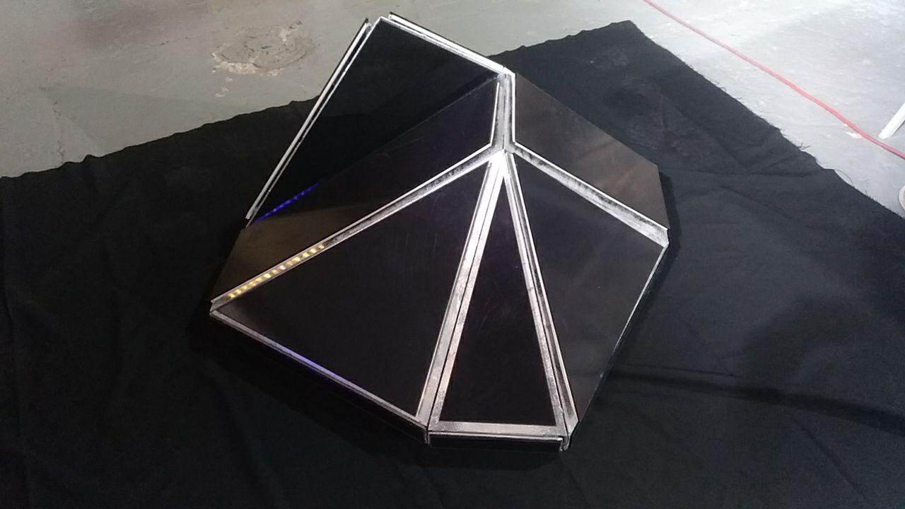
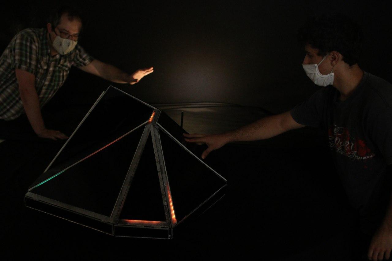
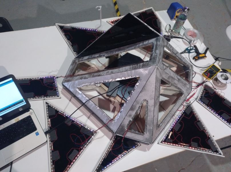
Hero shot
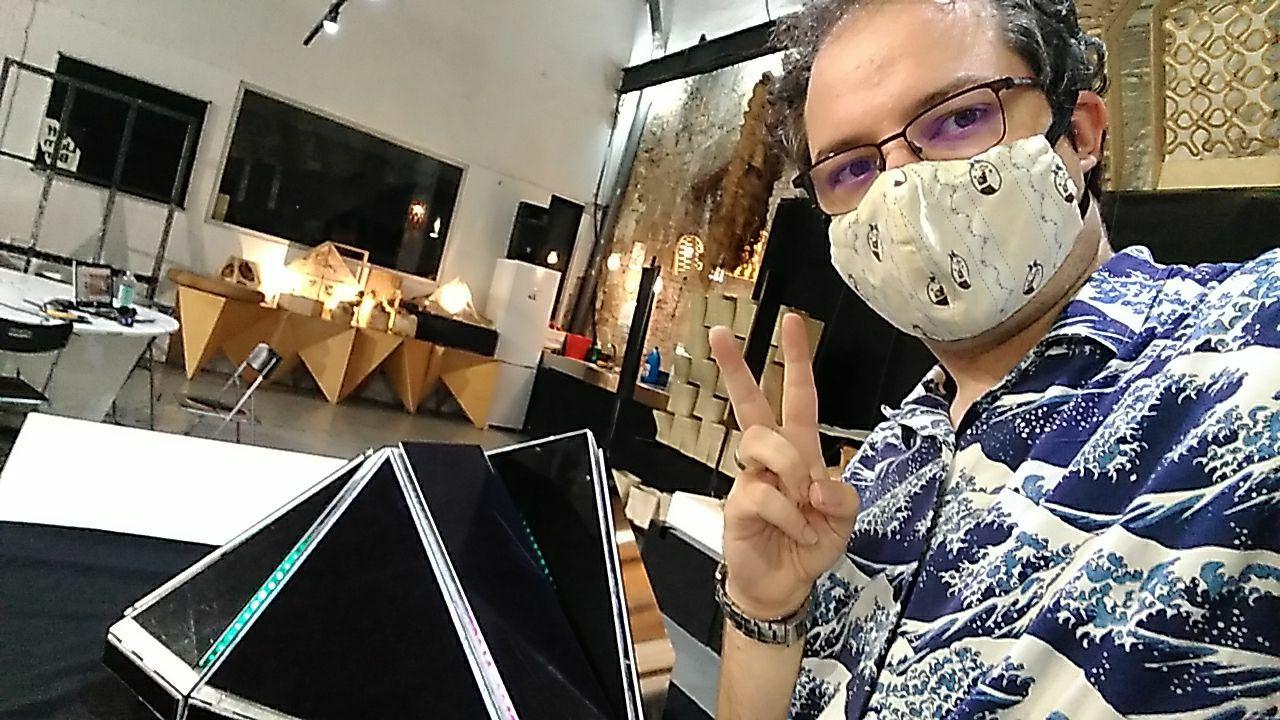
So here it is what I mounted for the presentation! And working (except from the button that I needed yet to wire all the frame)
It was wonderful < 3
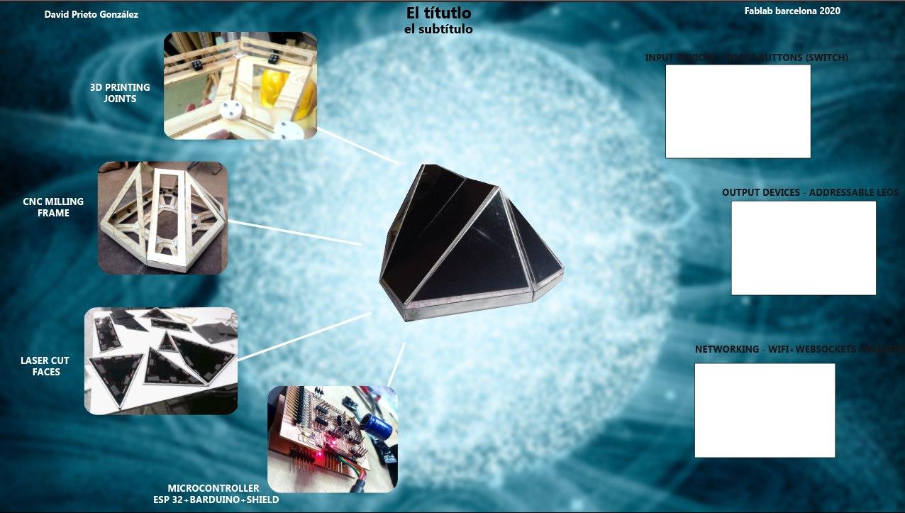
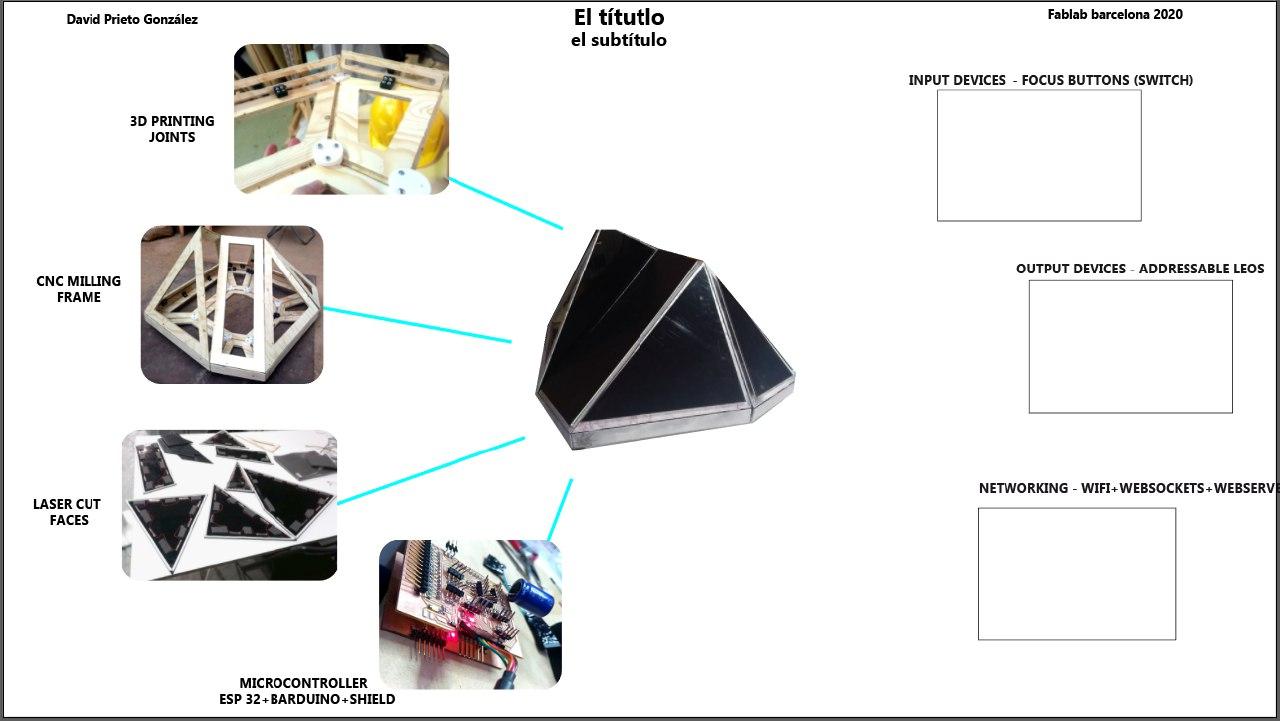
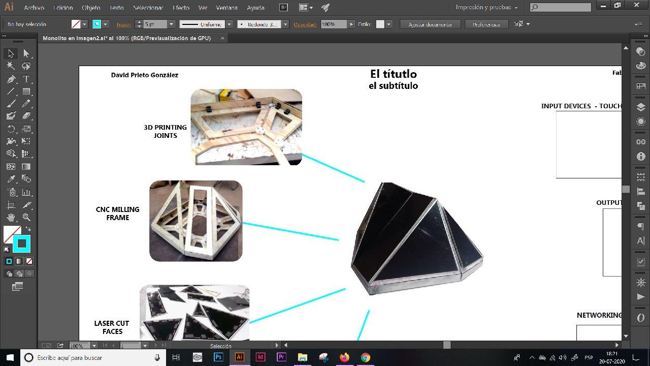
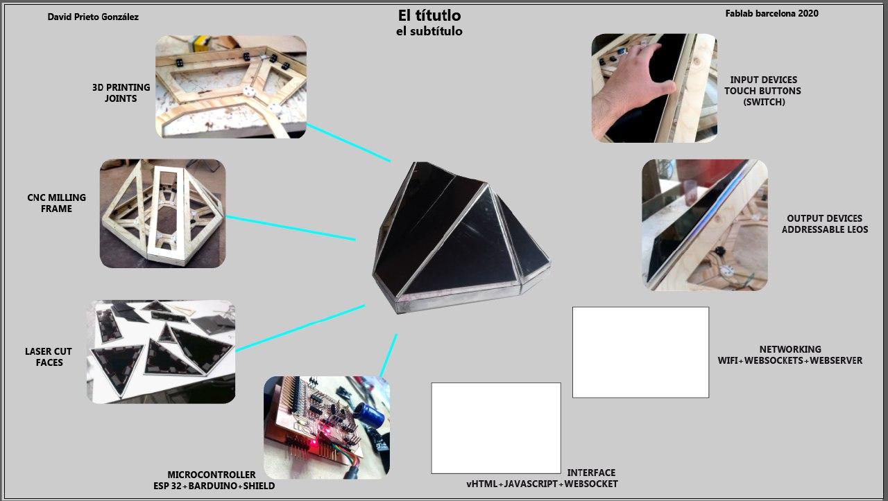
Creating the final presentation
Meanwhile I had also to make the final presentation. I had help from my partner Hilda and it was made in illustrator from the photos. Here is the process
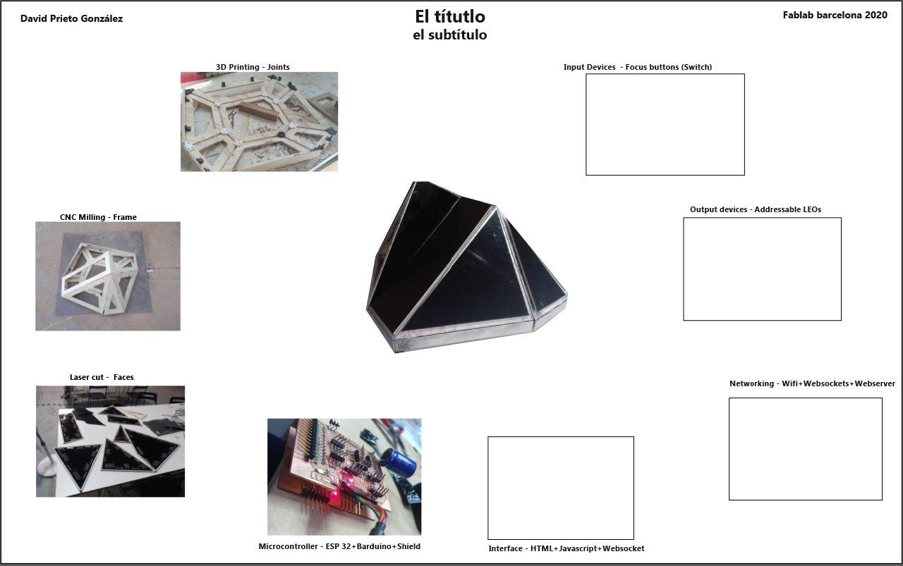
And of course the final presentation with a photo we took when we photoshoot the Monolith
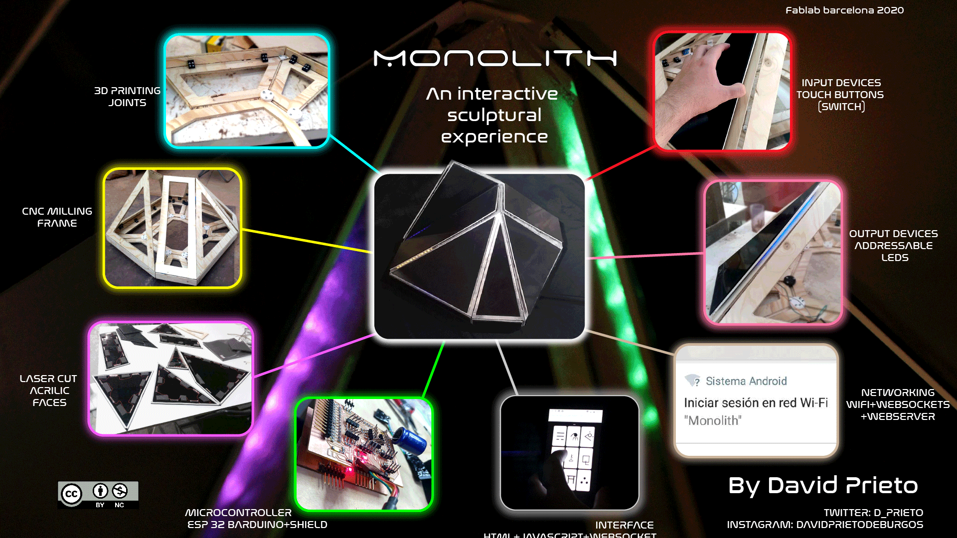
< 3
After the final presentation
Once the presentation is done and presented and I was asked if I programmed it all (that… I think I did) then I had to finish what was left. Now even breathing.
Finishing the wiring
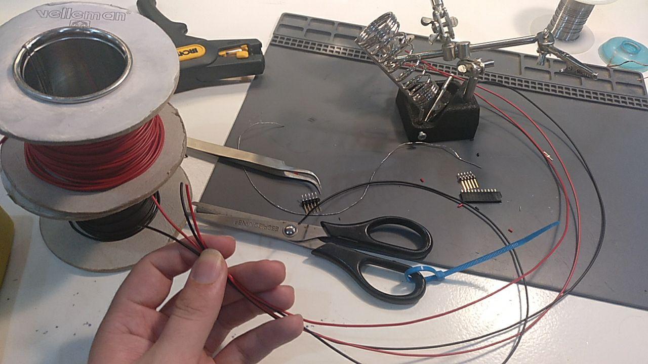
Ok, one thing that it’s not well documented is that since the faces can be 60 cms away from the board, I’d need some connectors between the face and the board. The board has some male connectors and the faces have female conectors so I would need one of each with space for 4 cables.
The connectors
I’m using black and red wire. The idea it’s that they will go black_red_black_red and the male connector of each face is black in one extreme and red in the other so it wouldn’t be so hard.
So first I cut the wire so I have 4 cables of same size.
Then I put the female connector where it doesn’t move and I have some good light.
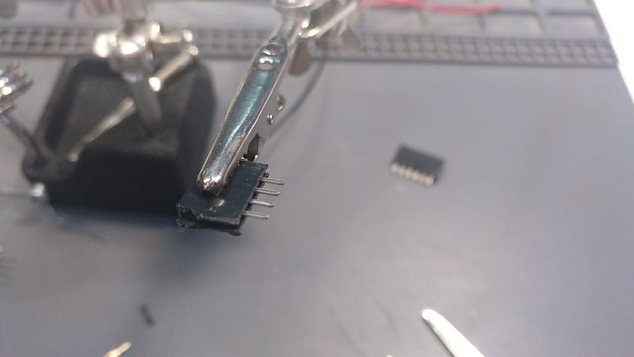
And I add some soldiering wire to each tip
Then I peel the cables with this little beauty that peels cable perfectly (and I had a lot of cable to peel!)
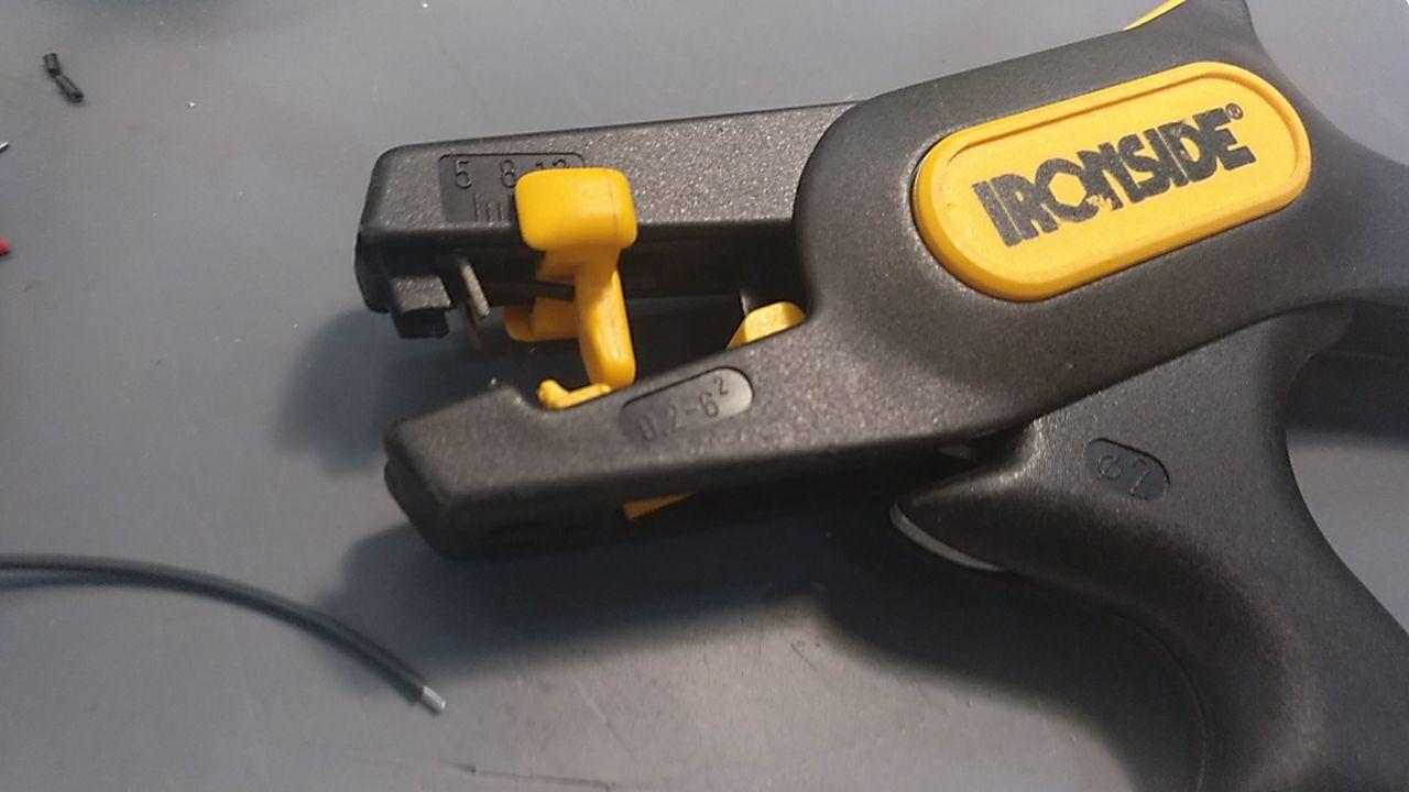 <3
<3
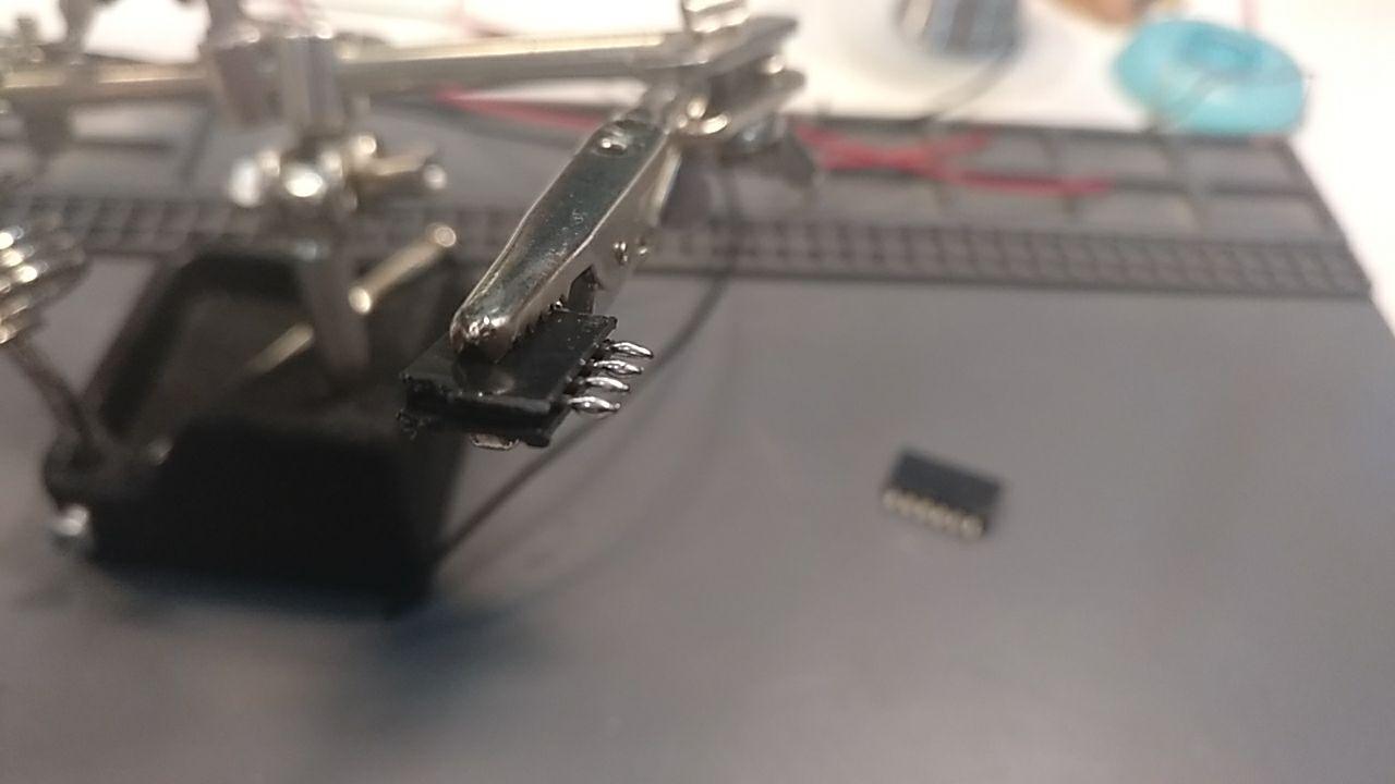
Then I soldier one by one
I twist the cable in pairs so they don’t suffle with other cables inside the Monolith.
And now the male connector! Same process
I usally test if it’s strong enough the cable.
And it’s done! You can if you want twist it so it doesn’t mess with other cables easily a bit more.
And this is the board with all the wires
TW: Wired mess
Finishing the faces
With that I can continue with the other 2 missing faces.
Yay!
All wired up!
Finishing the buttons
Ok, the other thing I need to finish is the ground connection of all the buttons. For that I have some aluminium tape that I put all over the edges. It’s not as conductive as the copper but it’s cheaper and I can connect through.
The alluminium tape and some corners.
I connected all the faces between them with a little of thin copper tape and wire alsothe 2 touching faces together so the signal goes stronger. With the multimeter the farther point it’s around 100 ohms. It peeps at least.
Final Bill of materials (BOM)
These are the materials to replicate the result of July shown in the presentation. I skipped the test materials for and milling.
Frame
1 sheet 1250x2400 of plywood
(screws for assuring the plywood to the sacrificial board of the CNC)
~150 gr of PLA for the 3D joints
~50 screws
Paint
1 white base print spray (Montana)
1 chrome finish print spray (Montana was used)
Faces
~10 meters of isolating white joint (1,5 package of 6 meters each)
1 sheet of black acrylic (1500 mm x 3000 mm, used 1500 x ~2000 mm)
472 addressable LEDs
1 sheet A3 (420x295 mmm) of polyurethane foam 10 mm
Design files
Remember to use download link as.. to download the files.
Grasshopper design and 3d frame
Frame
3D Joints
For the Joints there are separate files and the notation refers to the vertex they are refered to. Here you can see the vertex. Also you can see them in the grasshopper file
Lasercut faces
Useful links
- The assesment (quite important)
- Keep talking and nobody explodes