8. Computer controlled machining
# 8. Computer controlled machining
This week was affected by Covid19 so we could start designing and we had a class in CNC but we coudln’t use the CNC machine (for now)
Group Assigment adjustments
I made the group assigment after the assigment. And I made it after the final project (That has also CNC milling). But it was satisfying to be back and tweak the formulas.
Tue assembled the files and we test them. You can see her work here
What I’ve learnt
I learnt about the speed and feed and to tweak the formula of feedrate and its consequences.
A complement for a bathroom.
Concept
A friend of mine has a problem of living in a old building and the sink of her bathroom has problems sitting itself. We’re going to make a piece to hold it together and make it pretty.
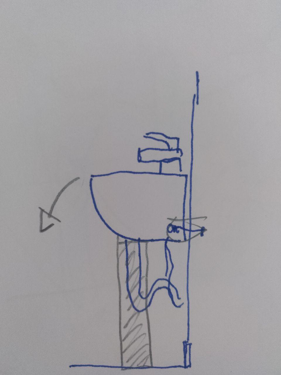
This the problem
We need to barnish everything properly because it’s a bathroom!
First we took photos and measurements
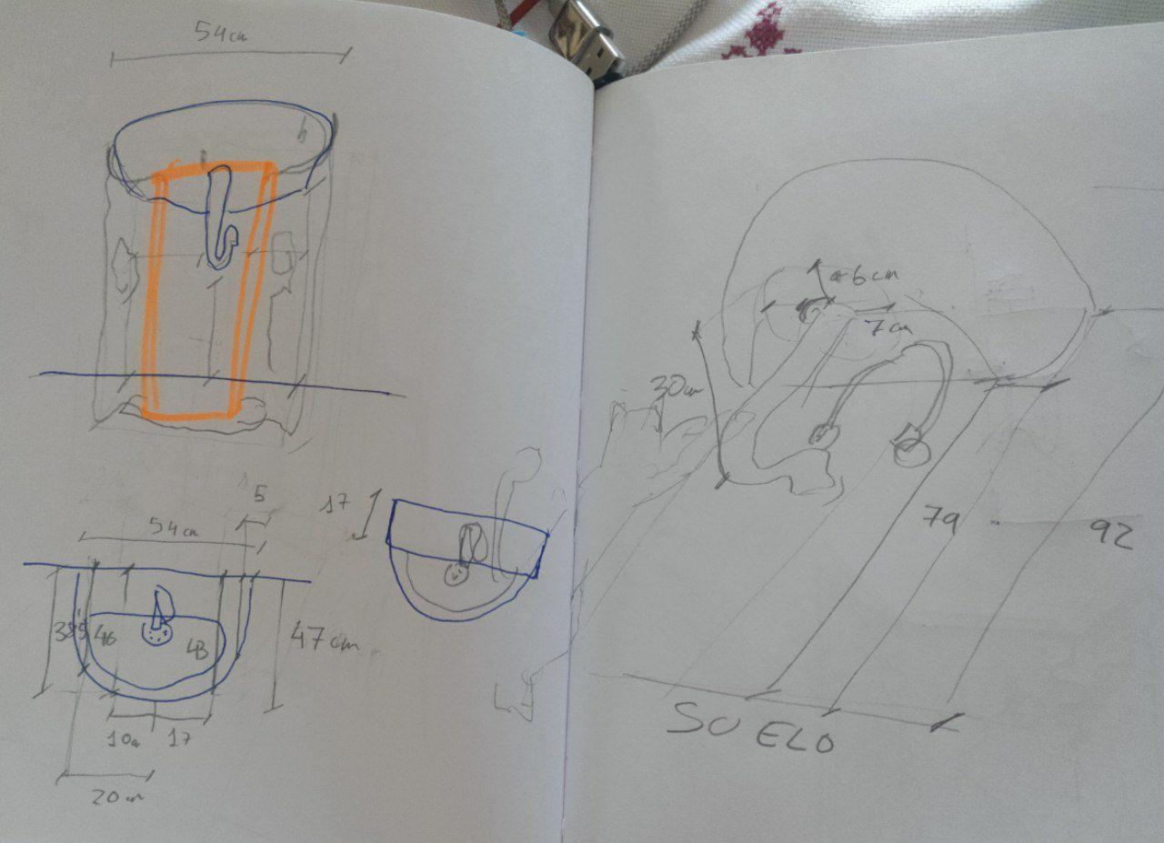
It was a tele-masurement because Covid19. A very 2020 thing
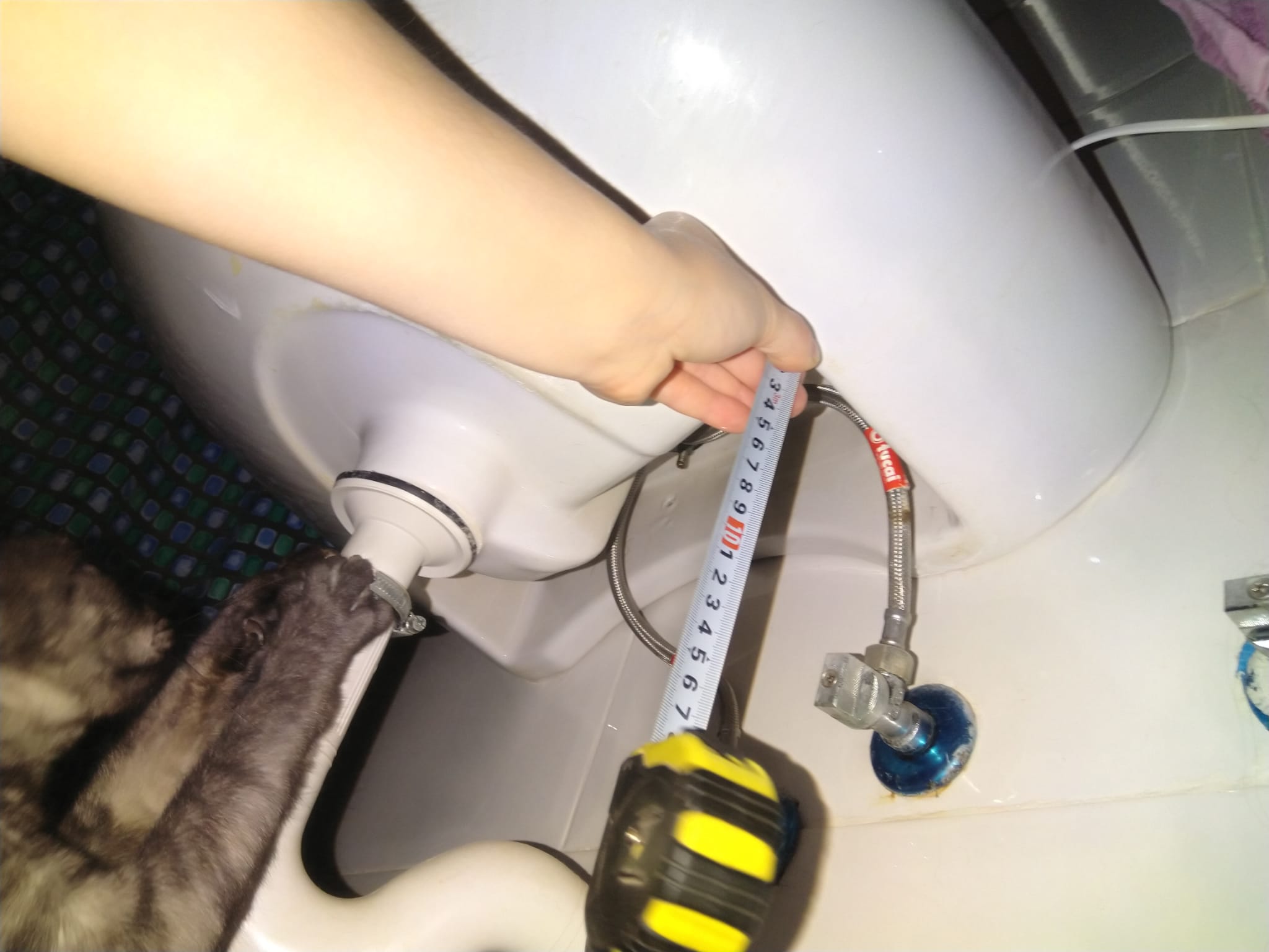
measurements incluyed cats
The idea it’s simple to set a footer and inside that footer put a couple of boards and barnish all of them. If the height is insuficent, just put some sheet under the footer.
This is the draft of the solution
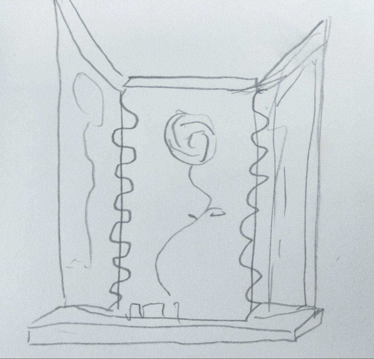
Also decorate it with Utena roses to make it rule.

Utena roses are cool
Now in Rhino this is the plan:
-
Make the model of the sink (simplified)
-
Make the model of the sheets of wood that I’m using and put them together
-
Decide and make the Joints
-
Decorate them with the Utena roses.
-
Figure out what to do with the RhinoCAM
Interlude when installing RhinoCAM
If you are in windows and install RhinoCAM it’s not going to start (and it will remember every time you start Rhino) if you don’t set your default template to have milimeters or inches. To do so you have to.
-
Ignore the message that the RhinoCAM is not going to start
-
Write the “new” command.
-
Set the “milimeters” (or if you’re a bad person or you are unlucky and live in the US “inches”) template.
-
Before pressing ok, mark the “Use this file when Rhino starts”
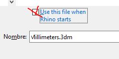
that tick
- Reset Rhino.
(that should make the trick. Like and subscribe)
Making the sink model in Rhino
With the measures I made an aproximation of where the sink is. Since I also have reference photos I can guess where it is.
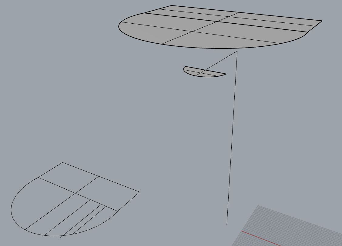
Result
Doing the boards.
I know that the board we have available it’s 15 mm thick (more less), so let’s start with thad measrument and add some boxes of 15 mm thickness.
First draft
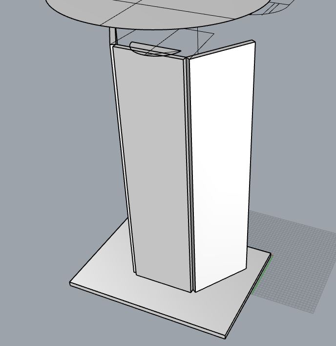
Ok, a base and 3 boards. The base it’s too big and probably we can use some horizontal reinforments (interior and exterior) to put everything in place.
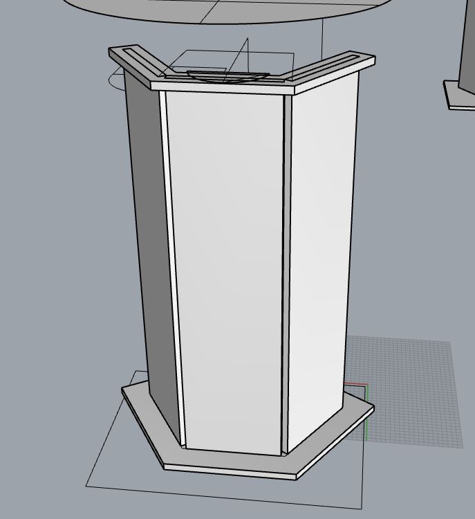
Second draft
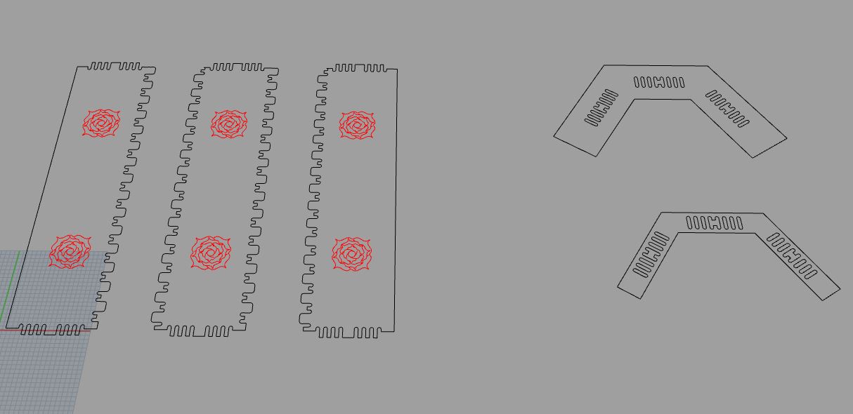
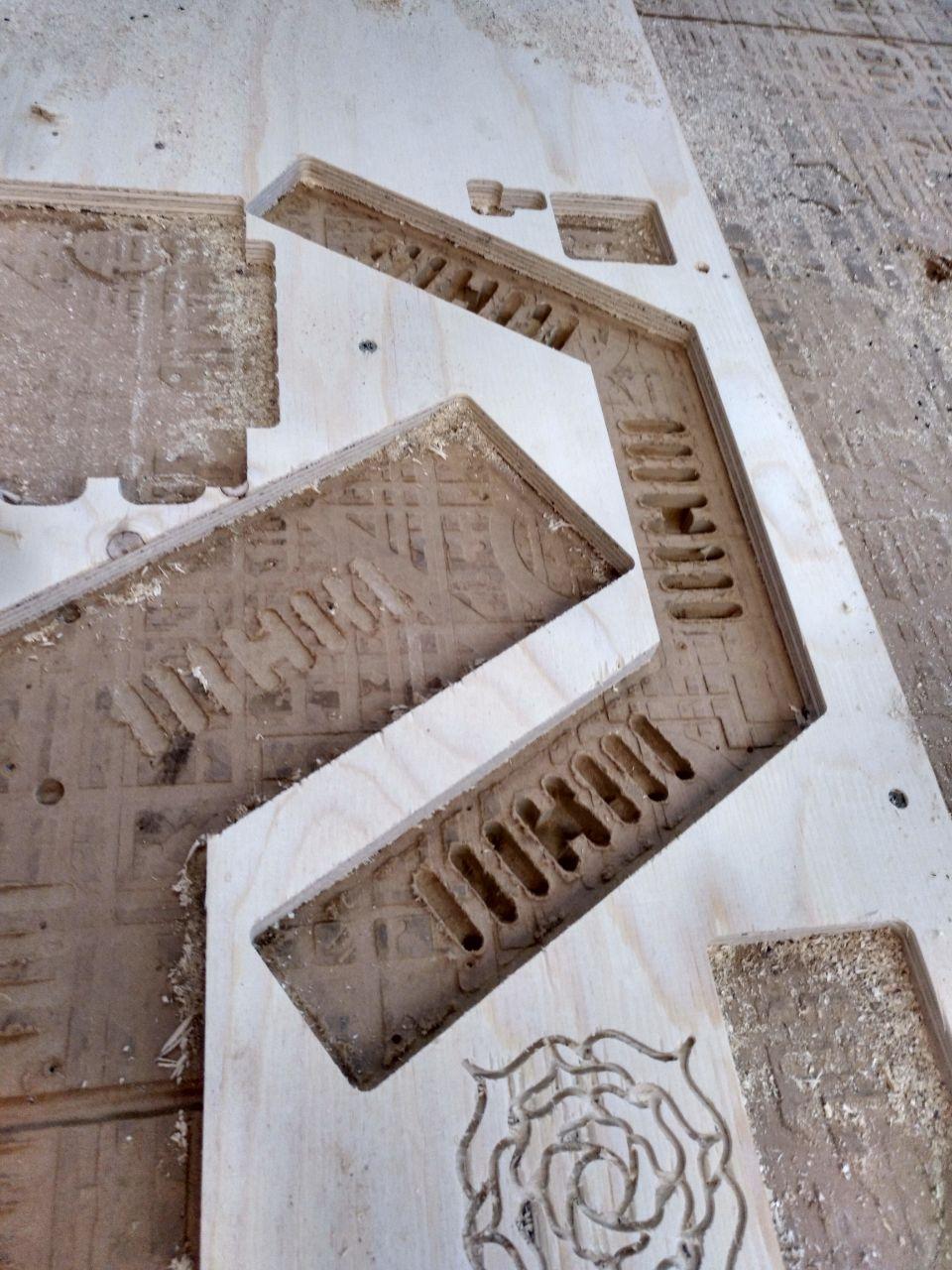
Once I have the pieces I want to join, I set them on the floor.
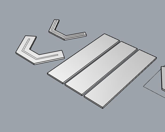
Boards on the floor ready to be treated
To know the joins I’m going to use I use these 50 digital joints. The pdf is a bit messy (because you open one pdf and another and another and go back is difficult and you have to open the “start.pdf” again) but I use the 3d dxf.
I also have the grasshopper I did here. But the same of other times happens, when you try to reuse the grasshopper is not as cool as it sounds, so I’ll take the drawing without scalling to make the template.
when grassopper is not as cool as you wish you have the line on the left
These are the joints I’m going to use here.
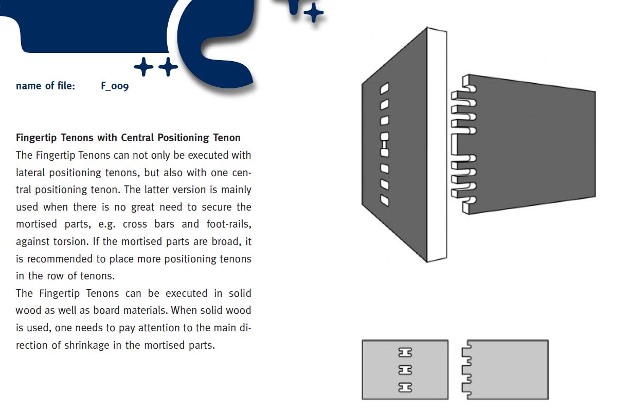
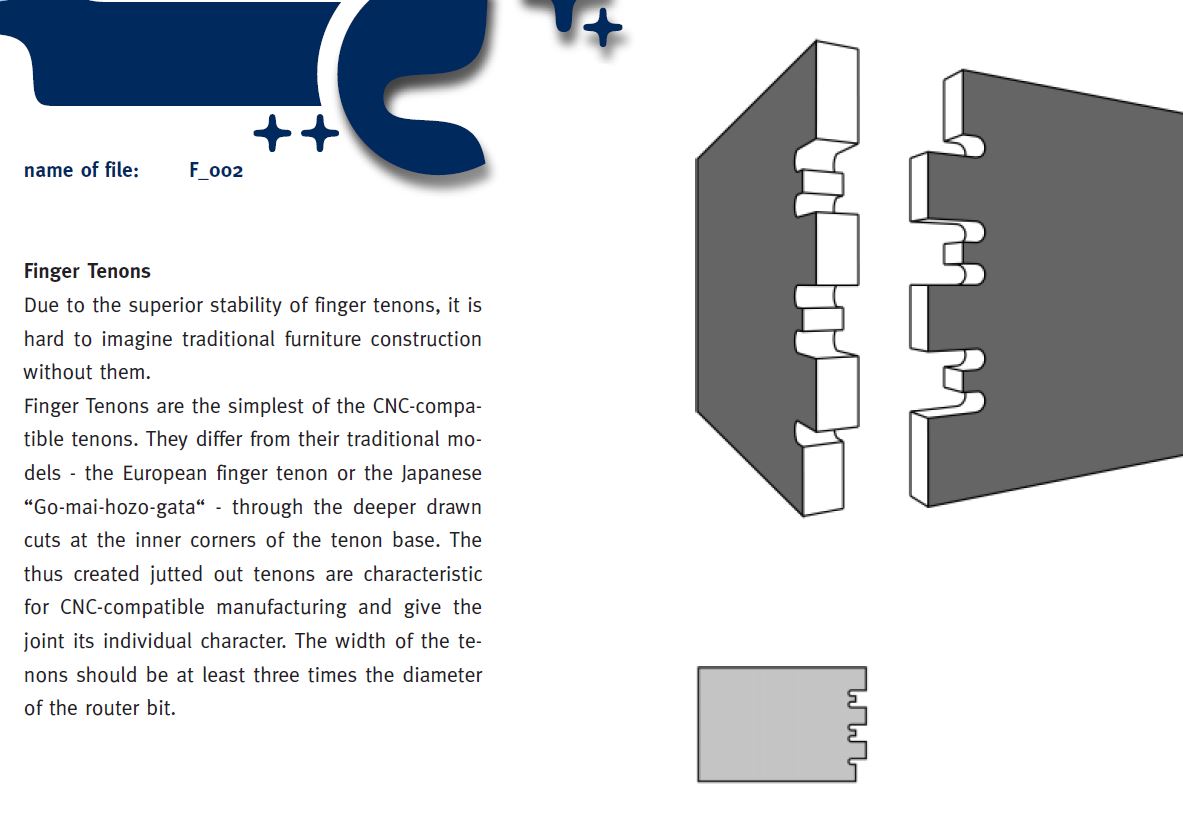
Joints used
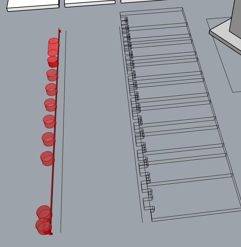
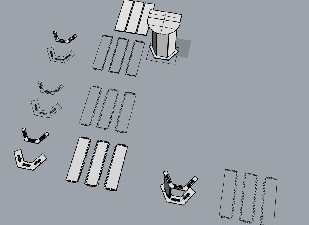
And here is the result:
When I made the set I saw that there is some collisions I have to fix.
collision
Now I have to
-
Fix the joints because they collide.
-
Make a little space between the pieces of 0.2 mm to handle them better.
-
Set the board of 2400 x 1250
-
Add the rose drawings
-
Go to RhinoCAM and set everything.
Fixing the joint collision.
In this case for fixing this problem I make a boolean operation to see how much do boards collide.
Using boolean intersection I see this tiny pieces of 0.86 mm maximum width.
so tiny
So I’ll move 1 mm one of the size (and the other stays the same)
And here I left the parts so when I make the kerf and I add the roses.
An ancient technique of CAD is that when you do something you copy it so you have the trace of what you’ve done for reference or going back
The rose design
This could be also in the 2D assigment but here it is. For this piece, my friend wanted a rose because of the role playing game, Vampire: the masquerade. Because she’s a Toreador and their symbol is a rose. Also because Utena and because roses are cool. I also wanted to design something to a bit of change from the Final Project.
I drew this in illustrator but even if I liked where this was heading to, I needed some more reference.
drafting draft
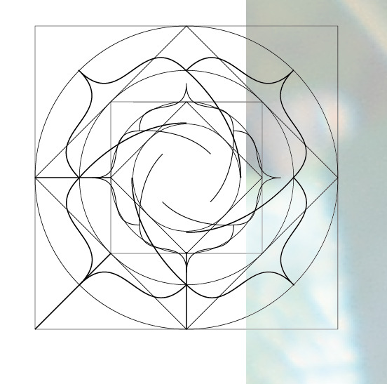
I took a reference and I draw a geometrization of it. This was the result:
squaring square
I wasn’t too convinced because it was too squared to be in a bathroom and for the person it was for (even if I’m fond of geometry, I have to step back!). So Hilda (my partner) showed me this trick:
How to do round fillets easily in illutrator along a curve
I learnt also how to make easily rounded fillets. These are the instructions:
-
Press V to have the black (default) selection tool.
-
Select a curve.
-
Press A to have the white (detail) selection tool.
-
Around the curve you will see in the corners some points that you can pull to make all the corners fillet around the curve.
-
Change back to the black selection tool to go to the next curve.
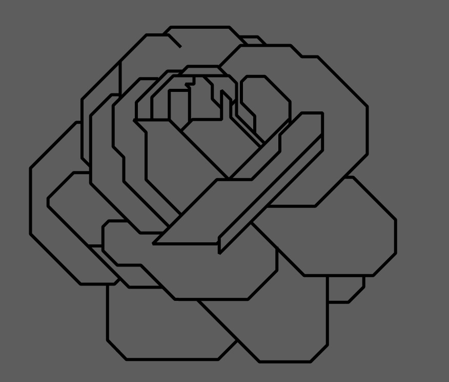
So after that I ended with this:

It wasn’t what my friend was looking for but it was fine anyway. But now that I had passed for the other “squared” way and seen reference, I was ready for doing another attempt using the draft. And… this was the result!
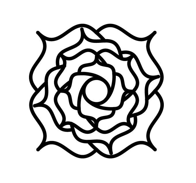
Now with more curves!
Configuring the cut and doing it!
Ok, now I have the files ready to upload to the cloud and start with the RhinoCAM to produce the files. This is going to take long
no nesting yet
But first I want to say that I had an error when I set the file and one of the faces I had was one of the faces was displaced on the Z axis.
Proof of the error

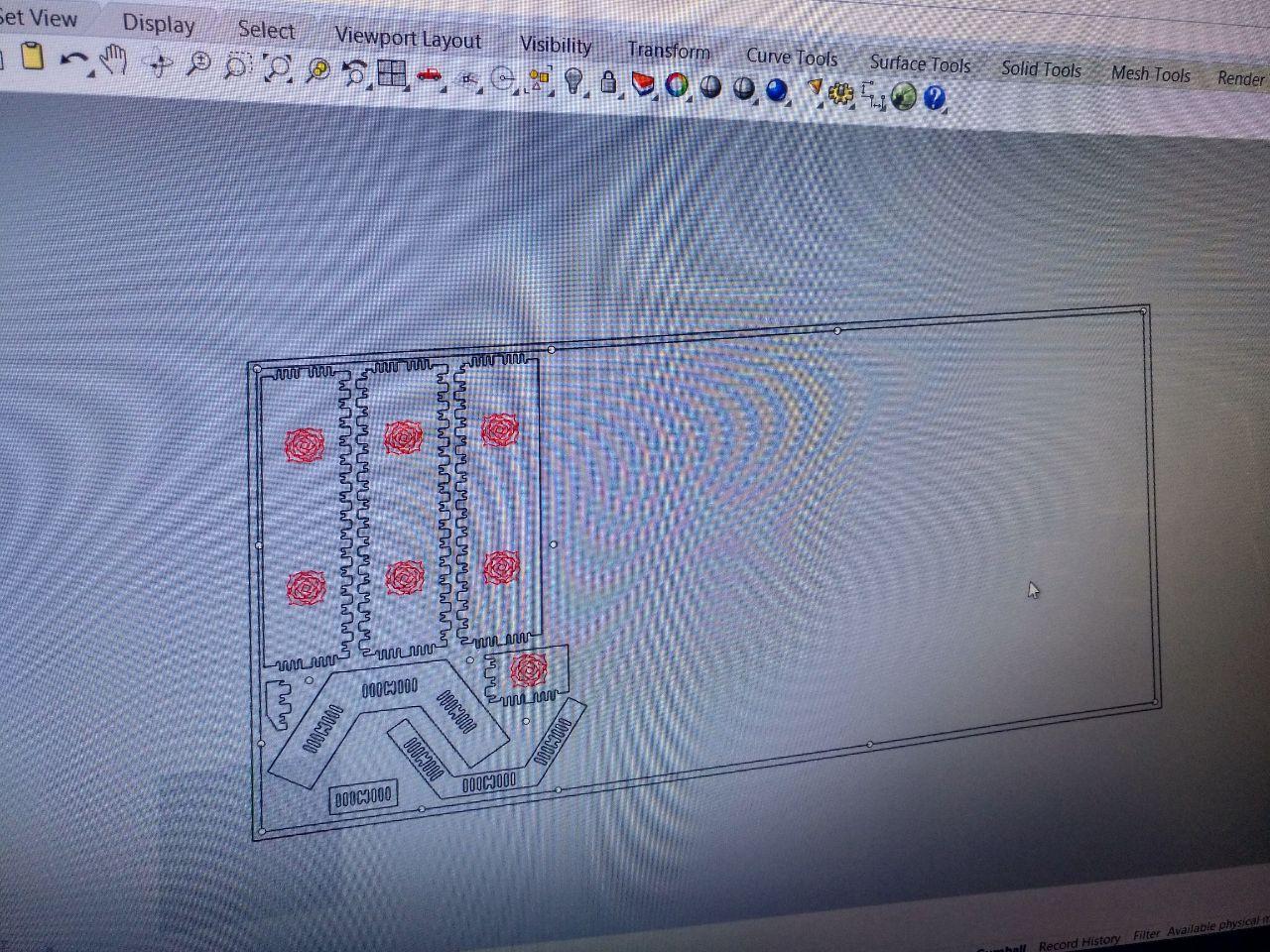
Once I’m in the computer. But first we want to try the joints so we don’t waste all the material. So I design this:
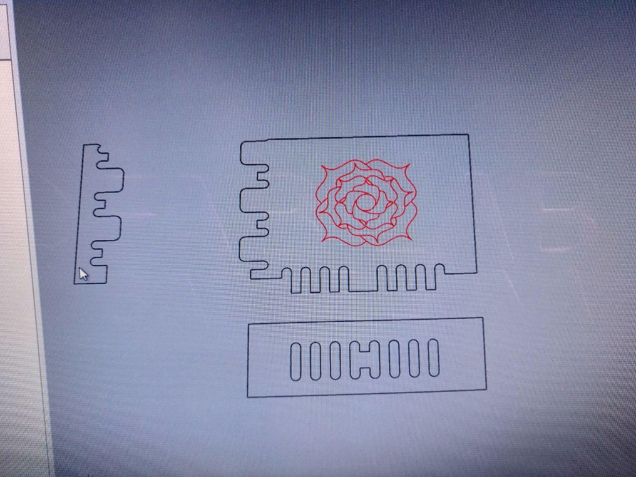
With this I can test if the rose is correct (because I’m using a 6mm mill) and if the joints fit each other. Josep helped me with all this process.
Once we have our basic geometry, we can set our stock.
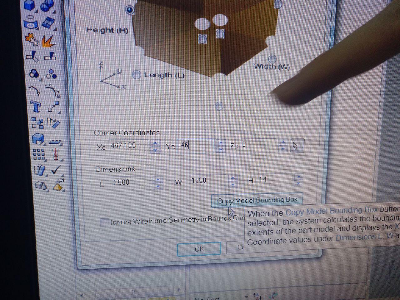
this photo has the dimensions of our stock but not the proper coordinates yet
The first thing we’re going to add is some screws to secure the board to the sacrificial board (Already in the CNC)
Also we have to set where are going to be the X 0, Y 0, Z0 of the machine. Usually in a corner of the stock.
The way we did it is to draw the sacrificial board (2400x1250 mm in horizontal because our machine works that way) in 2D and make an offset of 20 mm. Then we set points (not a polyline, just dots) around our geometry. That will be our first job.
To set the sacrificial board (the object that it’s from rhinocam, not the rhino object) you have to set a stock and put a z value. We’re going to set the z on the top of the surface.
remember to secure ALL THE BOARD
Types of jobs in RhinoCAM for CNC
The rhinoCAM works by jobs. Those jobs you post them into a .nc (gcode) file that the software of the machine reads and executes. You can post several jobs at once or do it one by one as you need.
Every job is a different operation and there are several. The 2D basics are profiling, engraving and pocketing.
-
Engrave goes along a line. This will be useful for the rose and also for the screws.
-
Pocketing makes a hole limited in space by a boundary, retiring all the content inside. For the holes unions I’m going to need a pocketing job.
-
Profiling allows you not to cut during a line but to profile so the result it’s the line (so the mill is offset from the boundary line selected). To cut the pieces I will use profiling.
Setting up the tool for rhinoCAM
Remember to save.
Saving is important and even if Rhino has autosave, rhinocam doesn’t. And for this I had to repeat almost everything. So control+S, my dudes.
The mill tool.
When you set this for the CNC you have to set up the specific tool, the specific mill you’re going to use. That means that you have to measure it, but in the options it’s also the speed of the tool during the cutting (that depends also on the material because it depends on the chipload).
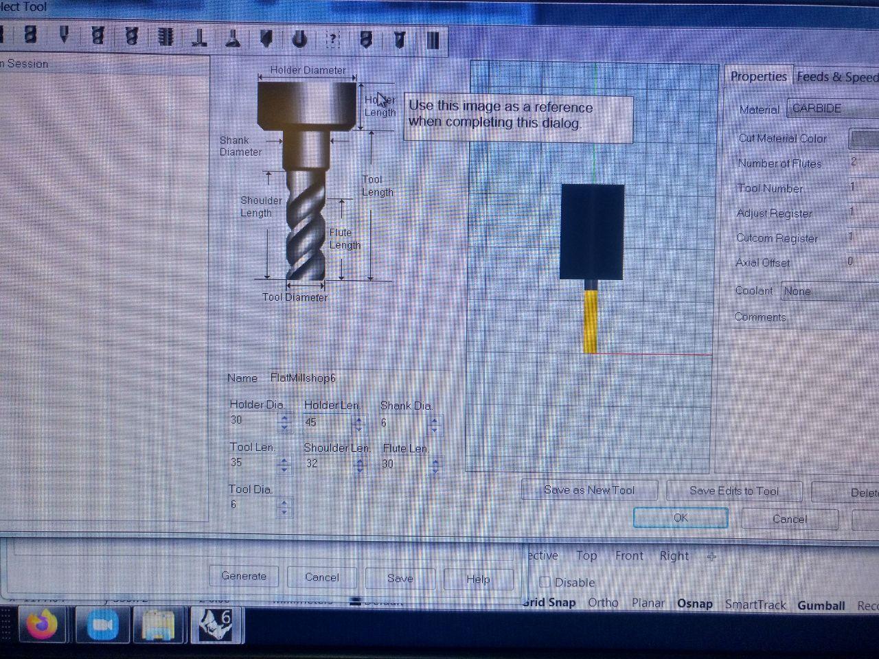
the only diference is that this one has only one flute
These are the settings of the tool I made. Knowing that we were going to use a 6mm mill and I could take from reference one of the mills that Josep had a photo. Pretty useful to take pictures of these settings because there are many of them.
For the speed we’re going to need these parameters.
Here I’m going to transform the imperial units to mm because it’s easier to me. So I have to put the size of the mill and the constant in the same units so they can fit. This is important because it’s not common. But it’s ok
The constant of chipload for plywood and size of the mill (6mm is around 1/4’‘) is between .011” - .013” that we will need to go back to mm. So it will be between 0.2794 and 0.3302 mm.
We can set in this spcefic machine RPM between 18 000 rpm and 24 000 rpm. That’s because is where the torque is. So with that we know can do a in between of the speed allowed that will work.
From 5029.2 mm/minute using a chipload of 0.2794 and 18 000 RPM to 7.924 mm/minute considering 0.3302 times 24 000 RPM.
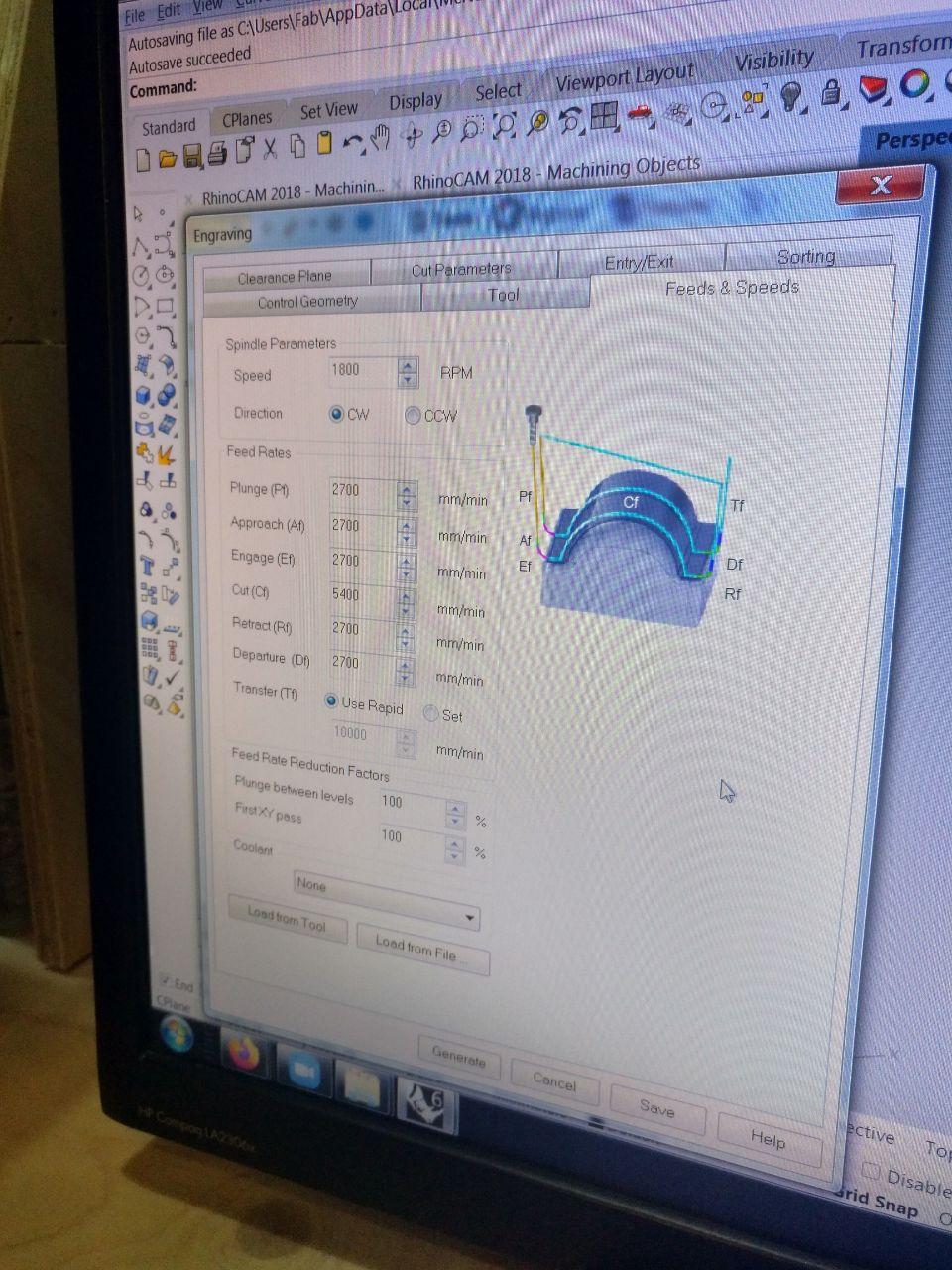
We’re going to use 5400 mm/min. From that we can imply the other speeds (in this case 2700) by dividing in half of the aproach and leaving speeds. In the case of wood is not so critical but depends on the material.
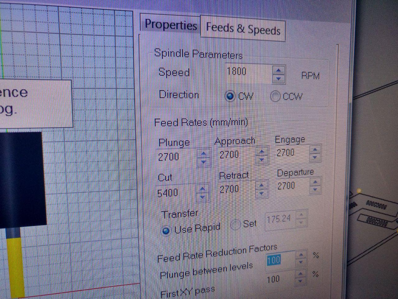
It says 1800 but is 18000 RPM
speeeeeed
Tip:
For the transfer is better to set 10000 and then “use rapid”. This is only for simulation purposes.
The clearance plane
For the clearance plane we’re going to use 20 mm (2cm) but once we set up the board it was so bended that it was safer to use 40 mm.
For a screwed and flat surface, 10 mm is enough.
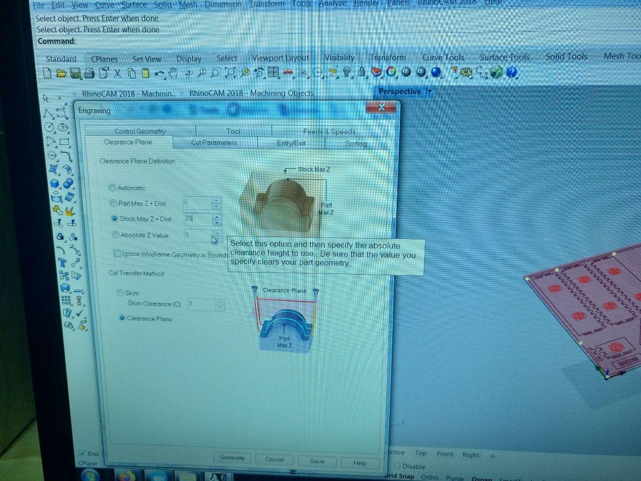
this is the tab of the clearance plane
The sorting
This is how the program is going to sort itself the different paths between them. We always use “Minimum distance sort”
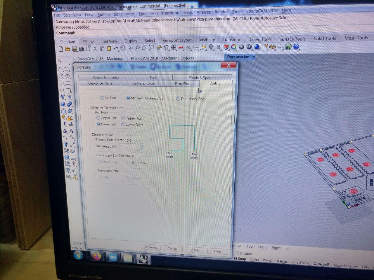
this is for all the jobs unless noted
The cut parameters (engraving)
Here in global parameters in the tolerance we always set “Tolerance 0.01”
And even if you have a “rough” and “finish” is barely used. We just adjust the rough cut. Each step shouldn’t be deeper than 1/2 diameter of the mill. So in this case for a mill of 6 mm we can dig 3 mm per each travel.
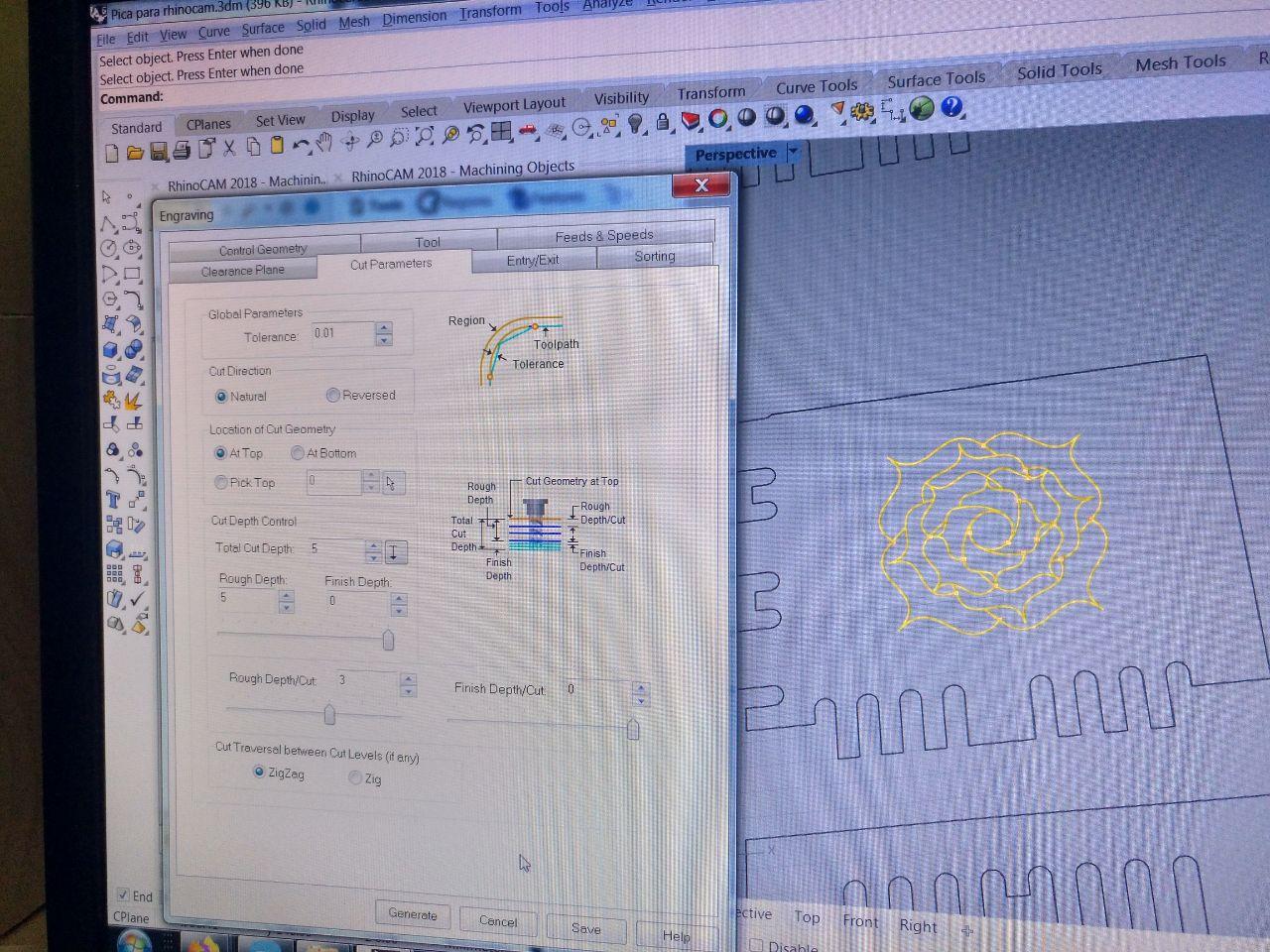
Also noted the zigzag/zig. It’s nicer (but it takes more time) to do only zig. If you do zig zag you’re going to mix climb and conventional.
For the screws (that’s an engraving) we’re going to just set 3 mm to mark wher to put the screws.
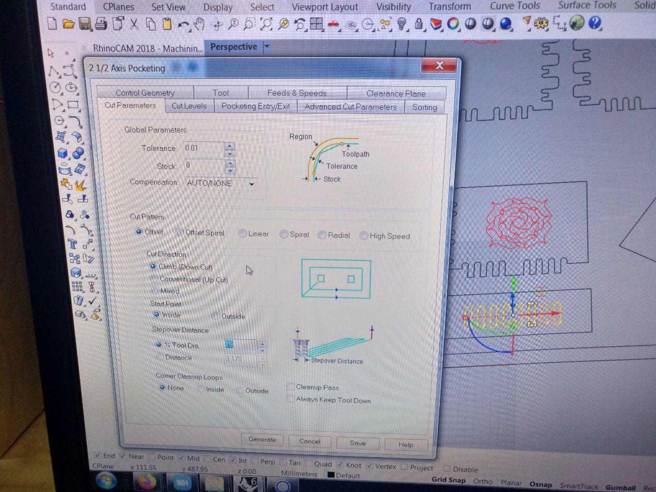
The cut parameters (pocketing)
Here is where we are going to use the settings as they come. From inside to outside and if it wants to slide we allow it.
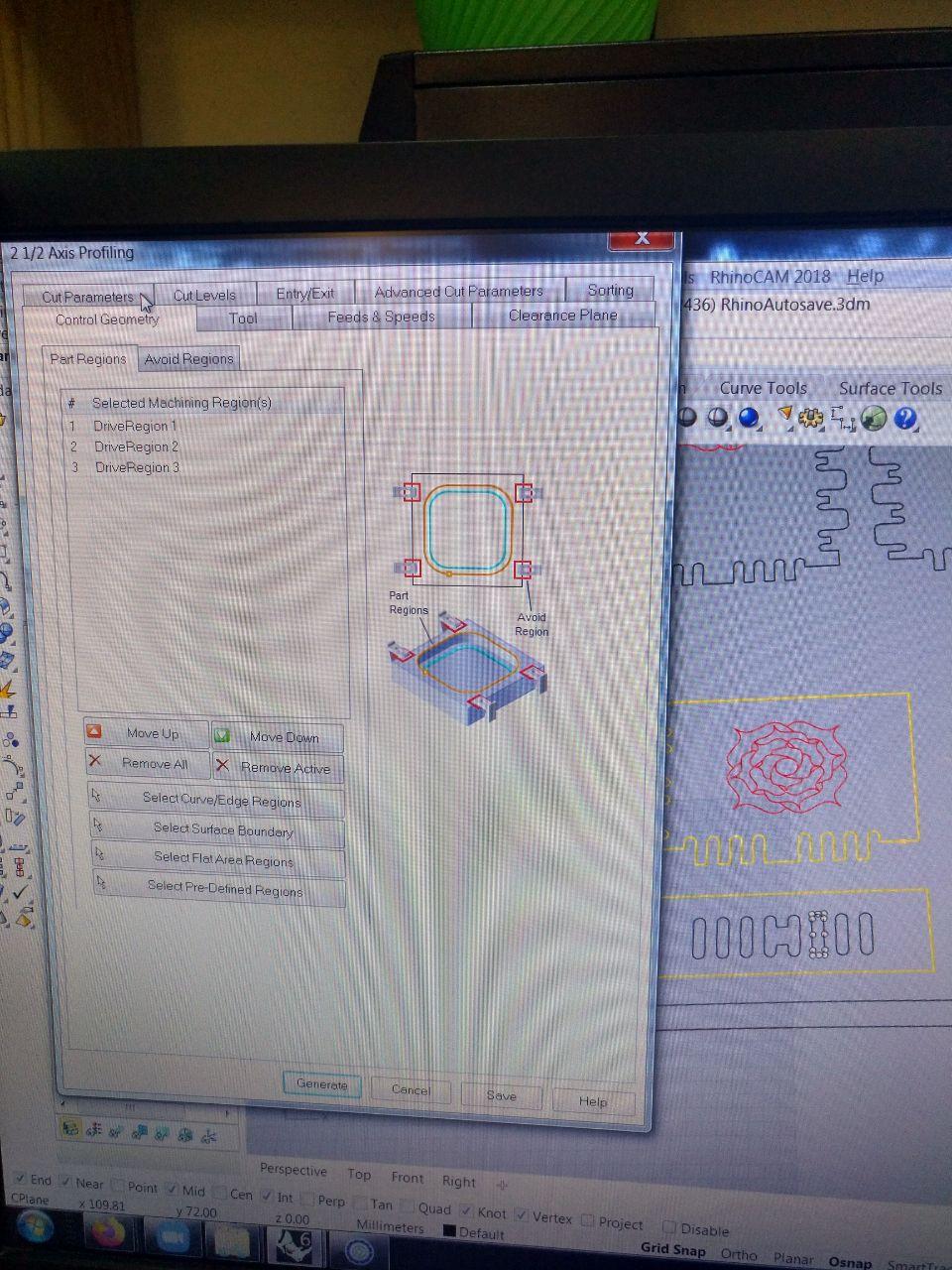
The cut parameters (profiling)
Here we need to check that it’s going to set properly the cut in the right place.
Control geometry
Here we set the curves that we’re going to use
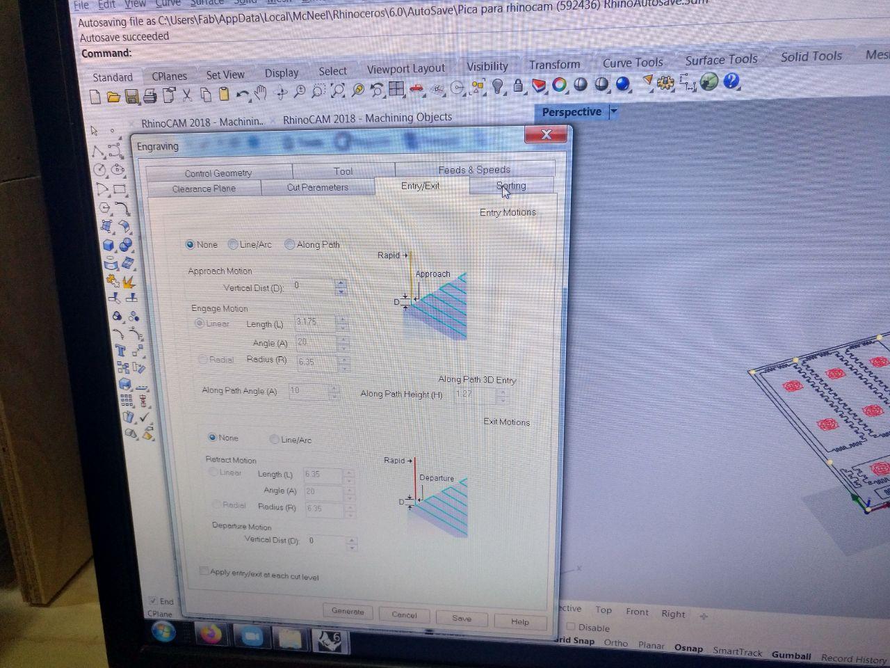
Entry / exit
Here it’s going to take the information of how the tool it’s going to go through the stock. In this case, we can afford (Since we’re cutting by half diameter deep per step) to don’t have any entry exit special movement. This depends on the material.
Advanced cut parameters
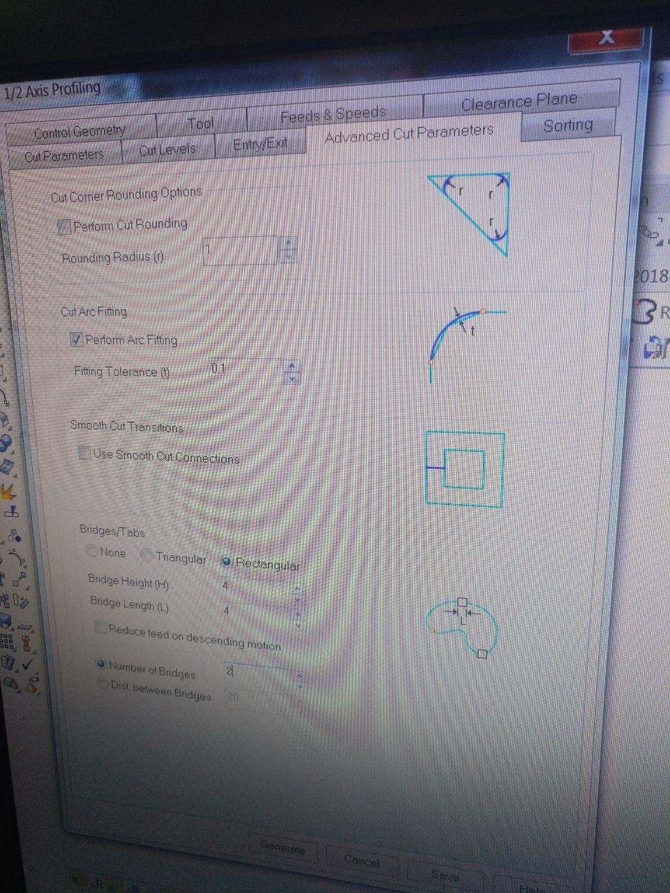
Here we set that I don’t want the cornering options because I already did them in design. I set the arc fittin 0.1 mm and if it’s profiling here we put the tabs for pieces to hold on while being cut. Set a couple of 4 by 4 should be fine.
Feeds & Speeds
Here it gets the info from the tool, but anyway it’s a good place to double check if everything is ok.
feeds and speeds seems the name of a new fast food franchise
Repeat
Once we have all that check, we repeat for each different job. You can duplicate jobs by right clic copy, right clic paste. My list is this one:
-
Screws (engraving)
-
Test rose (engraving)
-
Test holes (pocketing)
-
Test pieces (profiling)
-
Final roses (engraving)
-
Final holes (pocketing)
-
Final pieces (profiling)
That’s a lot! (when I’m used to in the laser machine just to set different colours for different orders and settings and seng one job.
Posting the jobs
Now it’s time to translate this into gcode. This is the time when we have to set the specifics of our machine because some use GRBL, other another GCODE conventions. So this is the time to double check that your machine is properly set.
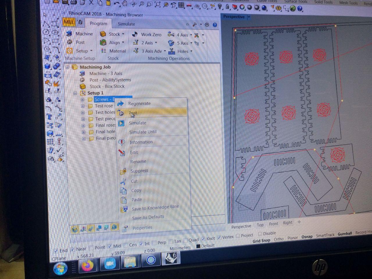
We can post several jobs at once if we need. In my case I’m going to generate the screw job (that’s first) and the test. Since I don’t have to change the tool it would be fine. We have time to make the other jobs since we have to check if the test goes well.
Now, FINALLY we can go to the machine.
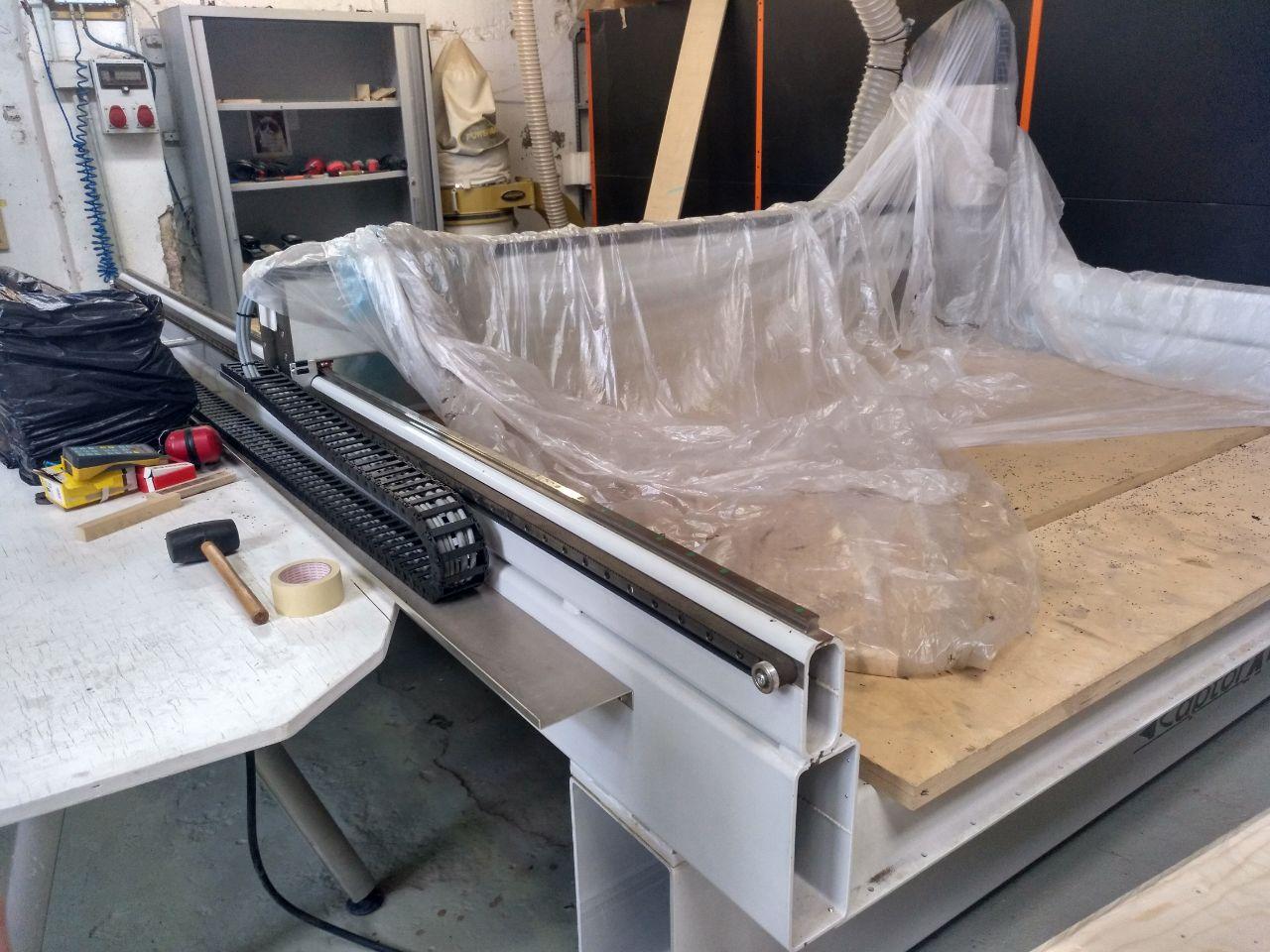
it seems that I’m the first one that uses the CNC after the lockdown
Some jobs can take a while to post
It’s important to remember that one job can take a while to post. That means 10 minutes. And the progress bar doesn’t help because it fills in 3 seconds and starts again.
Using the CNC. A journey that never ends.
Ok, so this is the PC with the software specific that reads gcode.
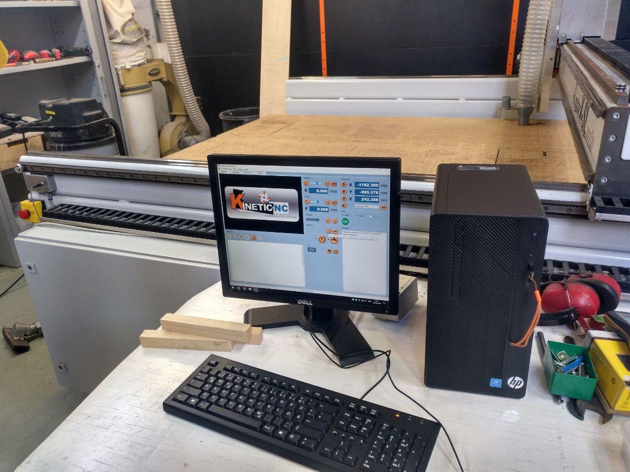
Once we have started the machine it needs to go to the 3 zeros to know where it is itself.
Safety First

The things that you need:
-
Safety glasses. Splinters gonna splint. Don’t let the go to your eyes.
-
Helmet. Possible problems on the roof.
-
Mask. 2020 fashion.
Setting the temporary axis.
We change then the holder and the mill to the 6mm that we plan to use. It takes a bit of practice. Use the tools to release the holder, take the good one. Realize that the 6 mm and the 8 mm have the number in a pretty similar way.
Once that’s done we put the board in a place that the sacrificial board it’s not too damaged.
Now we have to set the x and y.
To do that we manually move the machine in steps to get the middle of the mill in the corner of the board.
We don’t set the z jet because it’s too complicated because of the bending. We set the z using a macro and a calibrated button connected to the machine to do that for us. We move the machine a little to the middle of the board. And we double-click in the macro. That sets the z axis and we can have our temporary x/y/z ready.
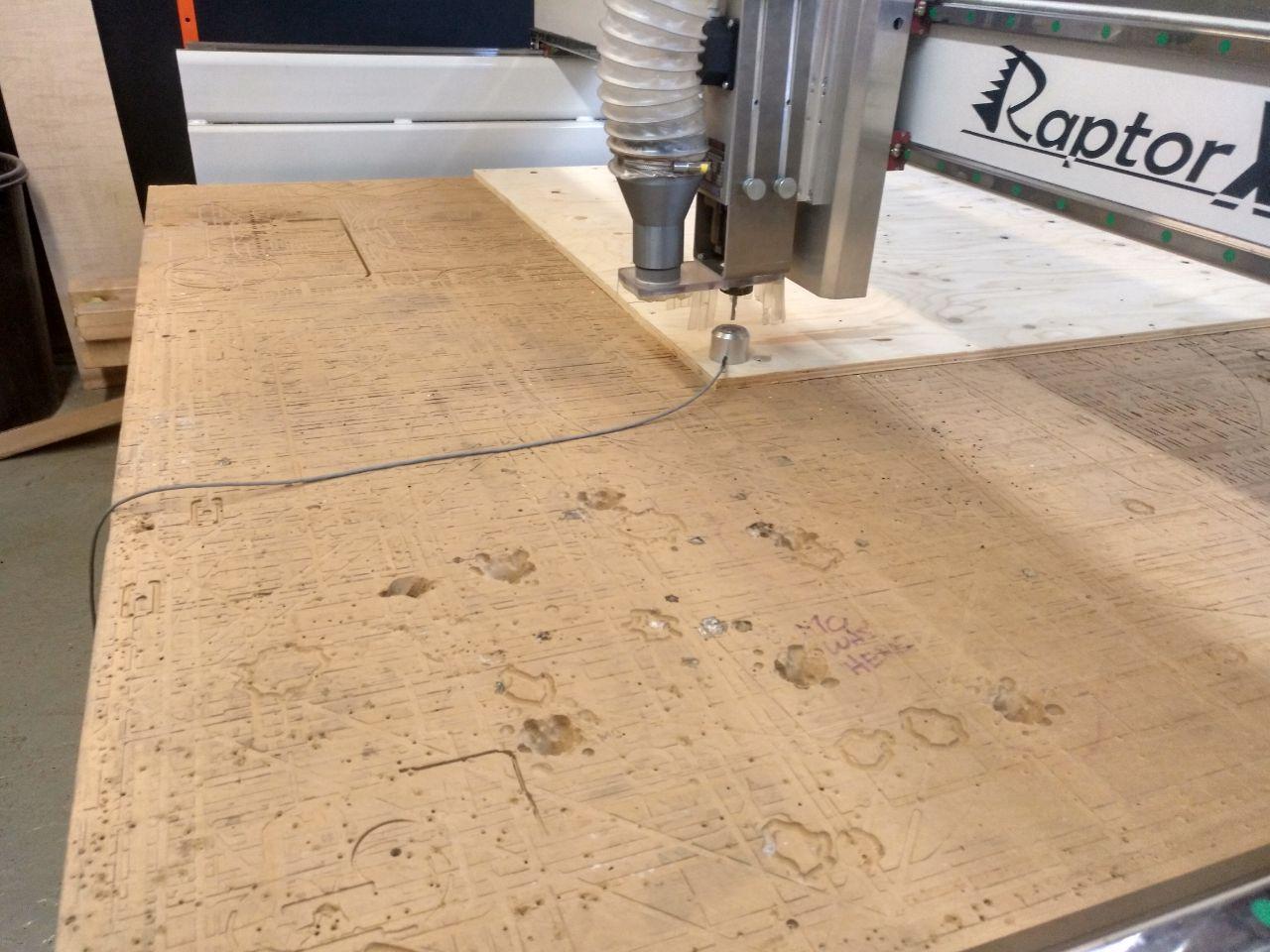
it’s kinda cute to see this big machine to press a little button
This has to match what we have set earlier in the rhinocam (that we set the zero in the top corner of the stock)
Screwing the board
As the board was specially bended, we changed the file to set the clearance plane 40 mm milimiters from the board instead of 20 mm. Then we passed and it was fine. We have the dots to screw the board
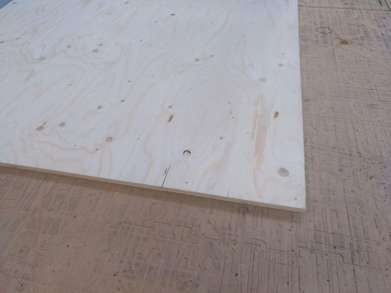
When you use the automatic screwdriver to screw the board to the sacrificial board there is a tip that is to screw to the end, screw out a bit and screw it in back again. This fixes better the screw to the board.
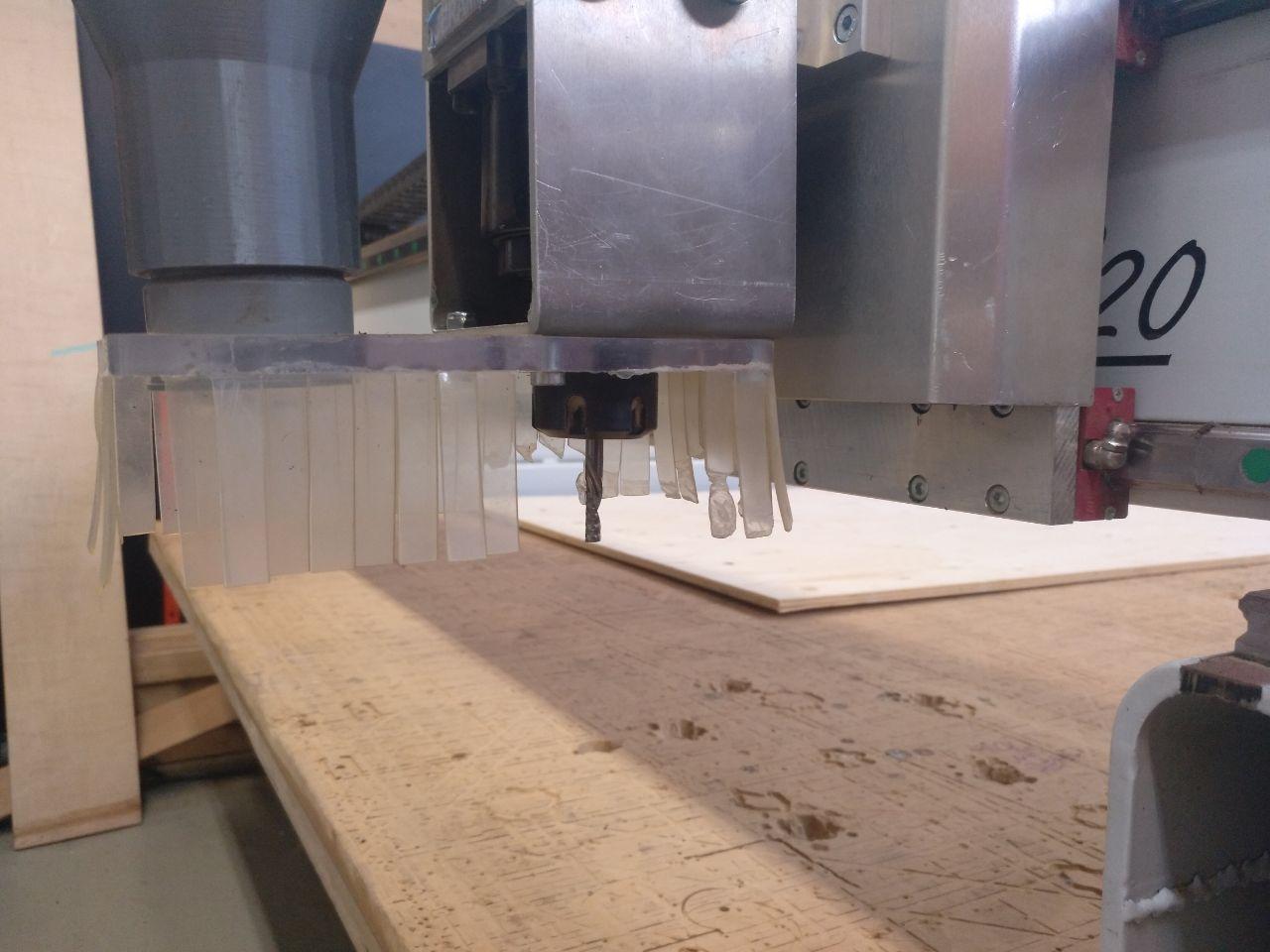
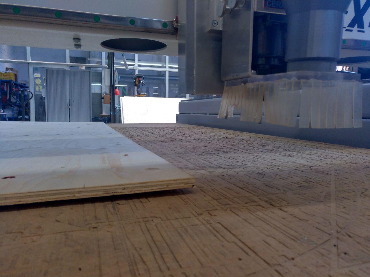
First test
Now that we have it all screwed we can send the test to figure out if the joints go well.
SPOILER ALERT: They don’t. But that’s the reason we made those test.
I also tested the rose and it was awful.
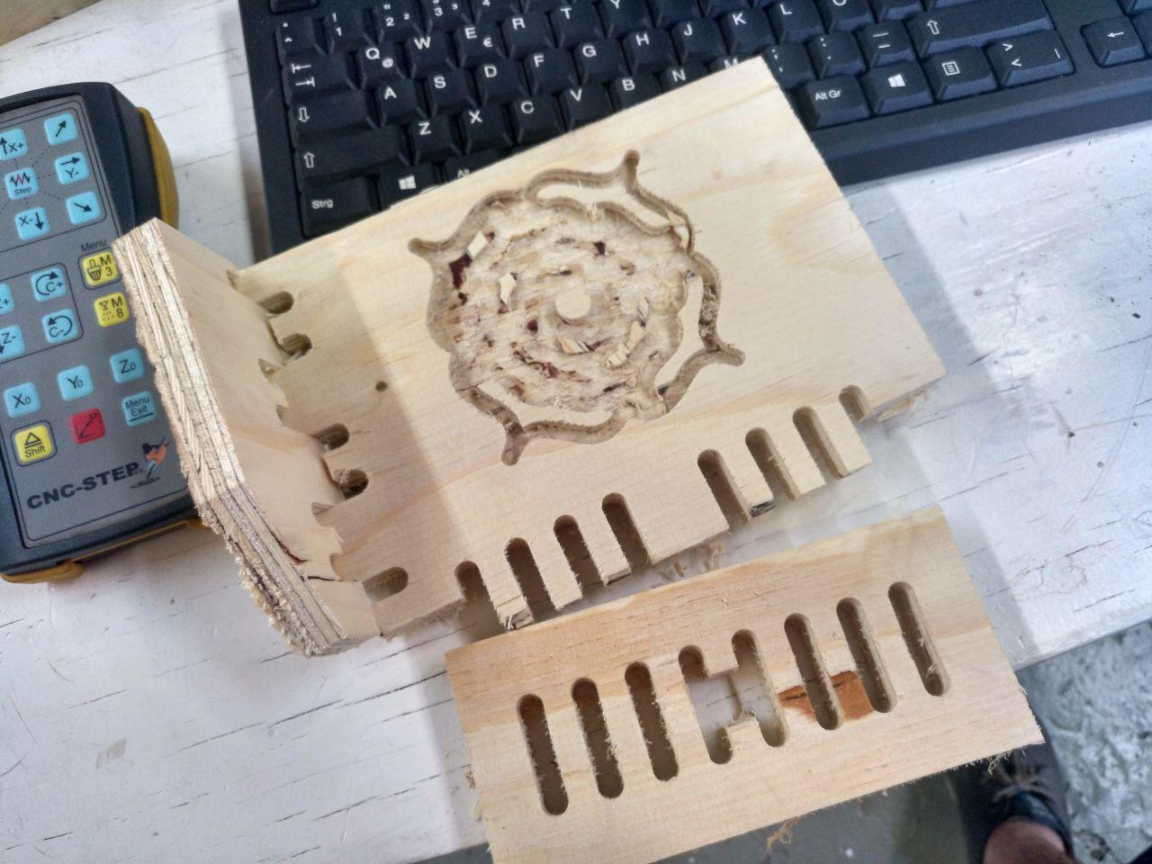
DAVID, PADRE, TE QUIERO
The wood it’s not suitable for this and the mill is too thick. So the middle elements go away.
The lateral joint work but they are too tight. The in and out fingers-holes doesn’t fit at all.
So I added some space to the holes (0.6 mm each size, son 1.2 mm total) and some in the joints (0.6 mm total)
Second test
I changed the file and set another mill (3mm mill) to do the Rose.
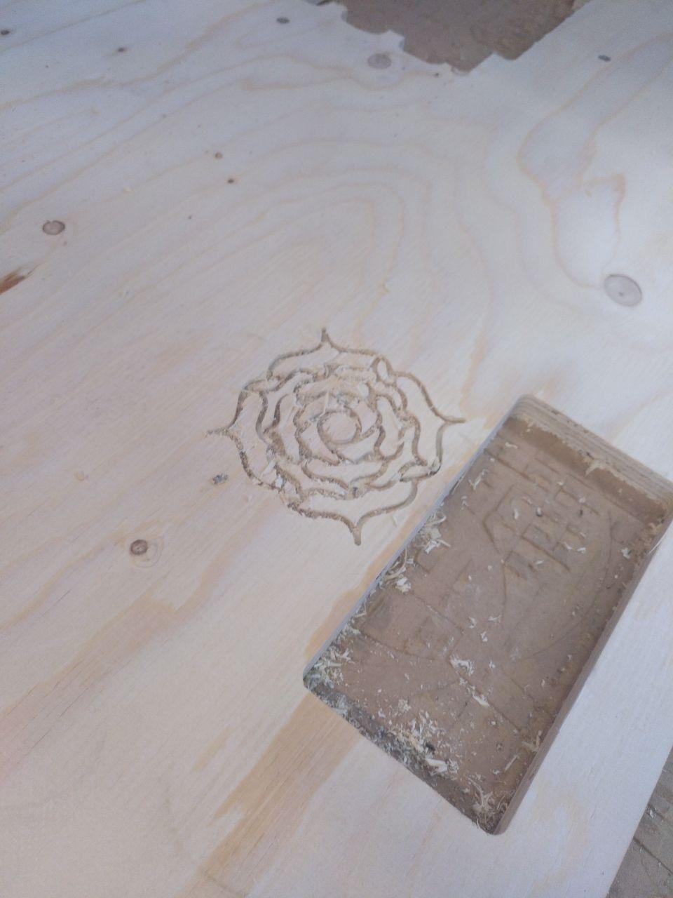
And this is way better.
I also made another (smaller) test and it went well.
Now I have to sand a lot from the other test because I want to store them.
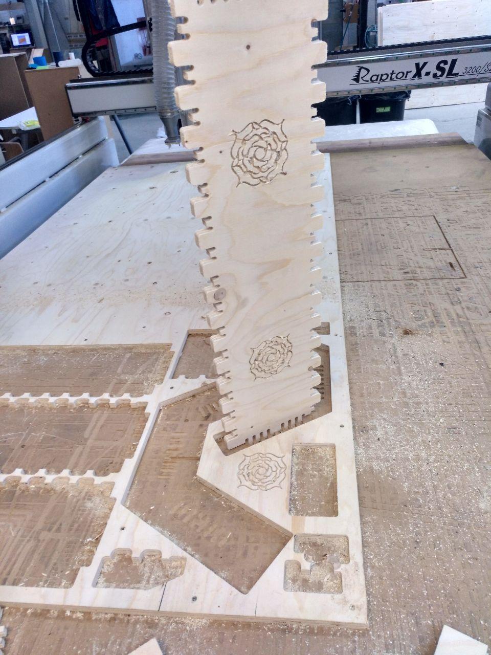
Final cut
So now I’m ready (after changing the files and post the jobs again). I sent first the roses because it was easy and the 3mm mill was already put on.
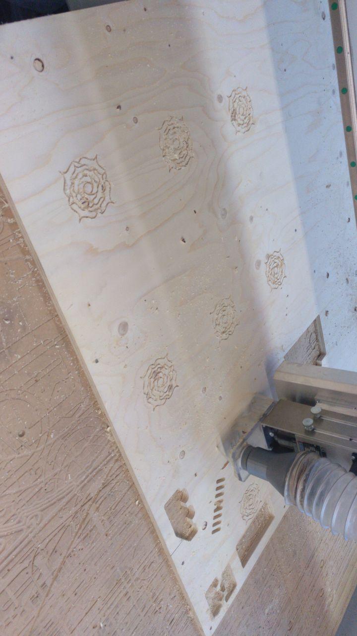
Now wait and see.
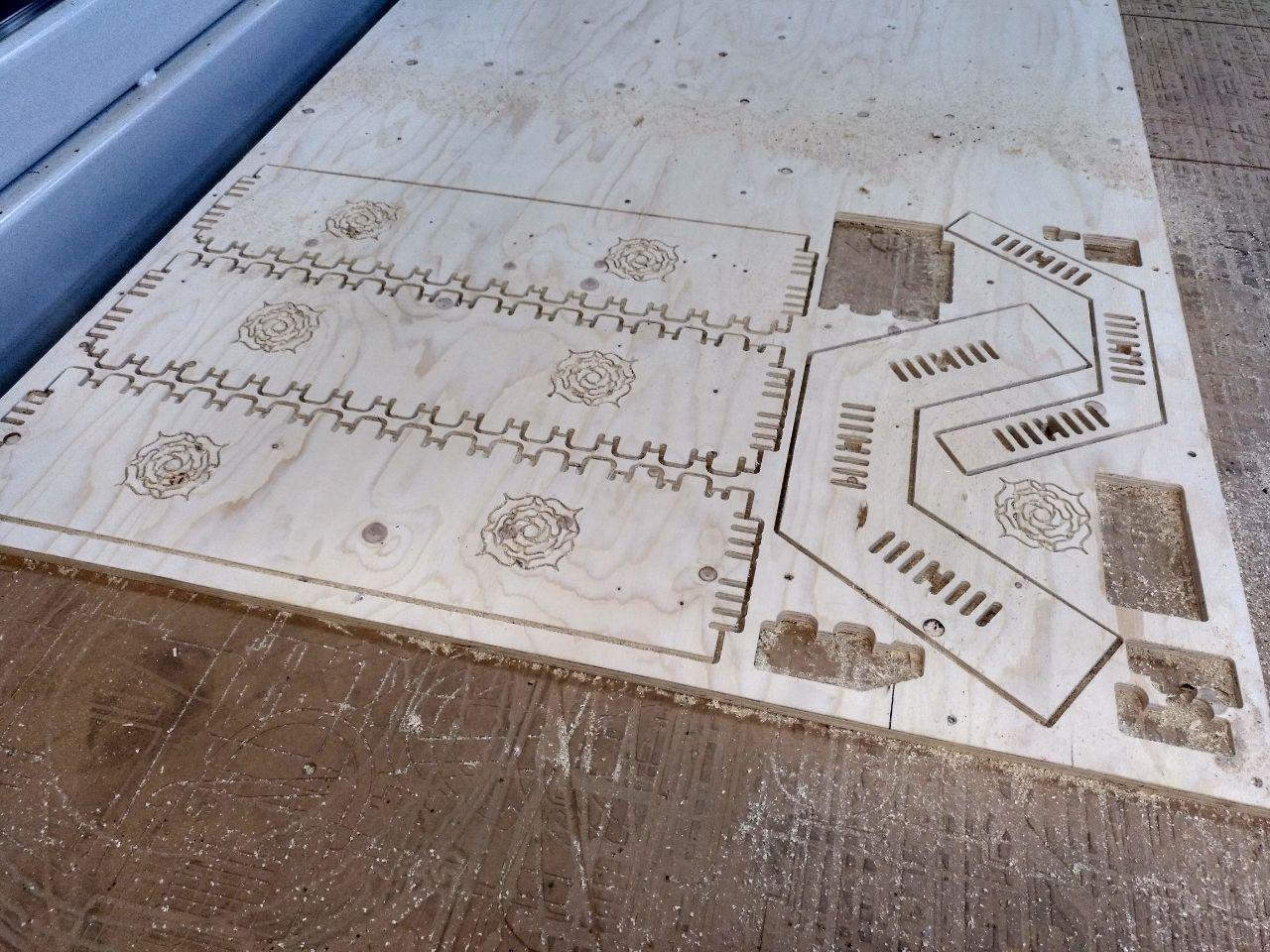
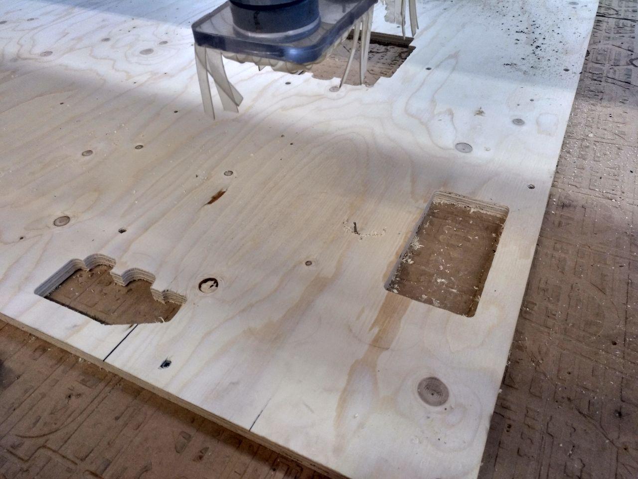
Done!
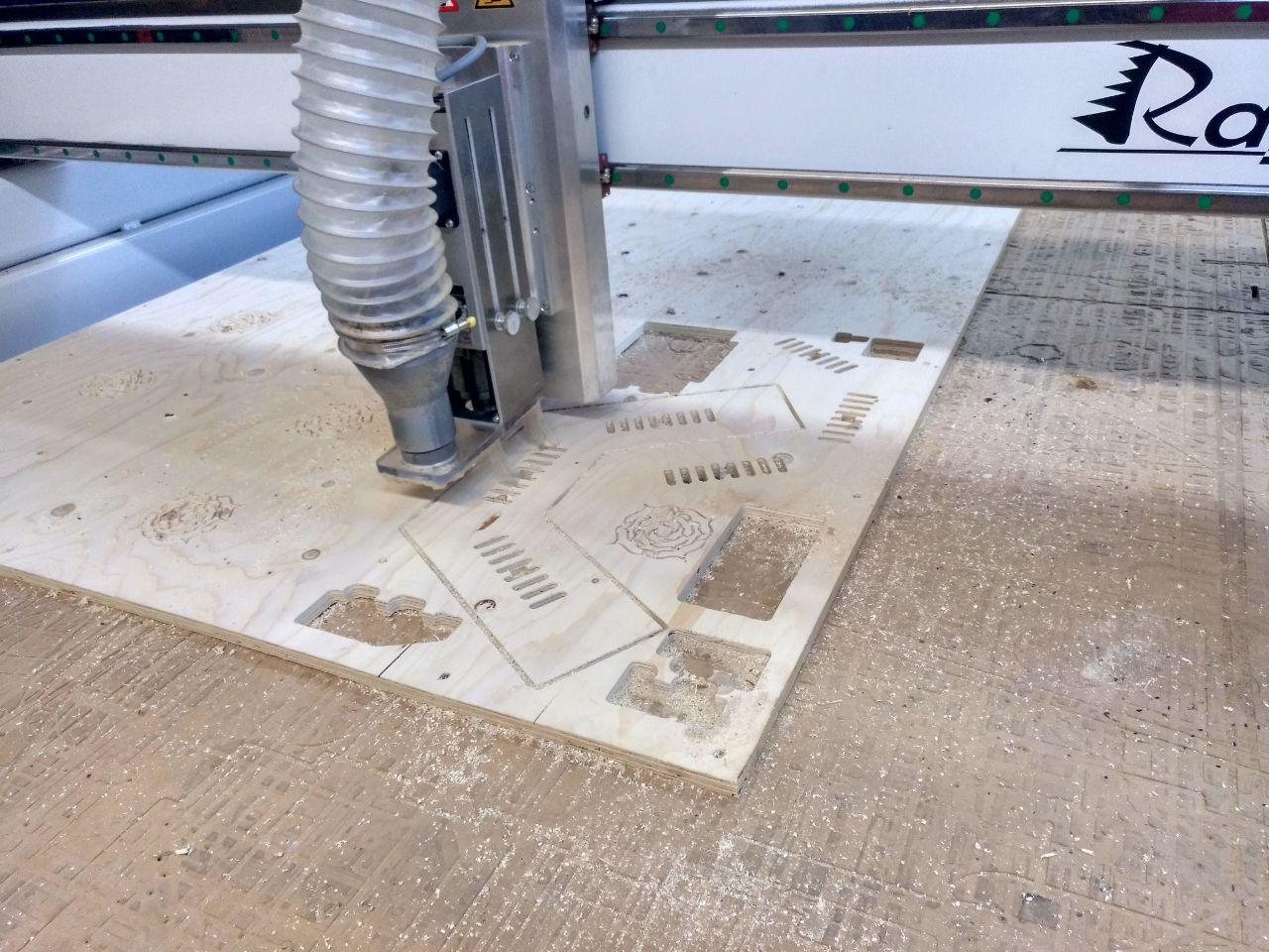
I used the vacuum machine to take the pieces out.
that’s a big hole!
When it was doing one of the pieces I felt that it was going too deep. We learnt that it was because one of the pieces was lower in the z axis. So the machine pocketed the sacrificial board.
at least the piece fits there
Mounting and hero shot
And we’re set to mount. It was easy and we only needed some patience and a rubber hammer.
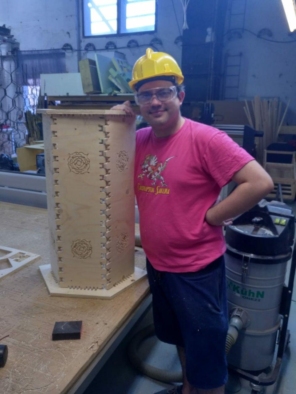
Behind the vacuum cleaning machine confabulating against me.
Using grashopper to prototype the Final Project.
My final project (an interative Monolith) is big enough to this assigment. And even if probably I’ll test different materials, I want to try to design this Monolith to be cut in CNC with plywood at least to test all the hinges, structural properties. Once I iterate with that I can change easily shape and materials (or at least that’s the idea).
In this step I have what you can see in the final project and here I’m going to write my journal about how do I smash myself with the computer in order to achieve the final design.

dramatization
_
Now I have several surfaces that, with effort I have a shape I want to follow and some parameters that can alter it.
Separate the faces and see them separately
Now it’s time to separate the faces of that brep (boundery faces). To do so, I opened an issue and also asked Edu, who give me a plugin name for grasshopper (fabtools). Also Arman, fellow student, give me a clue using orient component.
Now there are several components that I can use.
-
There is unroll (From the fabtools) that takes a brep and unfolds it on the ground.
-
There is orient that it’s native and you need to gave it the surfaces and the normal of those surfaces (attaching a plane to them for example) and the reference plane. (XY world by default)
-
Then you can use the component arrange geometry (From the fabtools plugin also) to separate the geometries in space.
Tranformations and you
In grasshopper there are several components that give you, as an output, a “tranformation”. That transformation can be usesful to replicate that tranformation. But in my case I want also to re-fold the geometries I’ll modify because I want to test how they fit together.
So for that there is a component called inverse transform that will, do just that with the tranformation. Later you can use the generic transform component that needs a geometry and your inversed transformation and voilà.
Diferent faces, different treatments
Now I know that I have several faces that have several treatments. I only want 7 of the total faces to be pushable. And the bottom face needs a space to have switch the Monolith on and an opener that could be remove in order to change the battery.
Join the joinery j-union
Now it’s time to think of how this pieces are going to connect together. In my case I want to make the joinery of this piramid of the Monolith, so I need a hidden joint with several angles. So I needed to go back to grashopper so I can set this complex geometry no with joints.
Ok, for now we have several links. This one about 50 digital joints was specially useful.
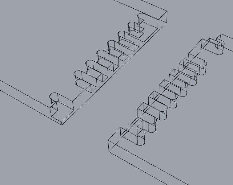
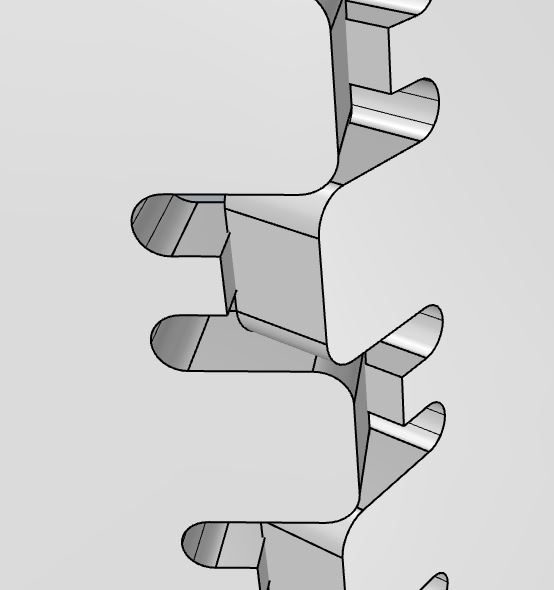
Figuring out what to do with the joints
This is meant to be a 90 degrees hidden finger joint. But I (almost) have no 90 degrees joint, so I need a more generic version so I can adjust the angle.
So I made some drawings to guess what do I have to do.
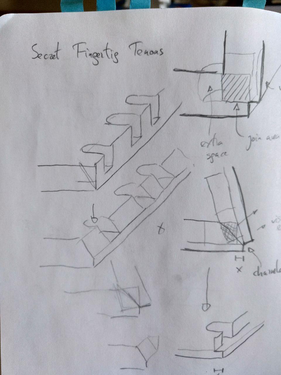
trying to guess what’s the joint space
There was an option of make a angle but later I guessed that I wouldn’t need it (at least for now) so for now straight milling.
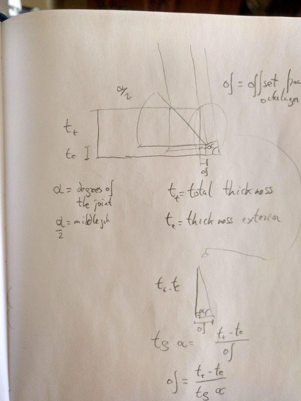
Trigonometry operations are easier doing by hand than in grasshopper sometimes
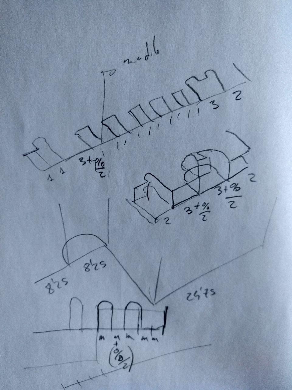
Also I had problems with the modularity because well, you have a specific size but the size of your joint maybe it’s not just exactly 23 modules long. So in the example there is a couple of fingers bigger. I used that to absorb the module (the rest of the division of the modules) so no mater the size (from 10 modules up) you can make it.
calculations done by drawing
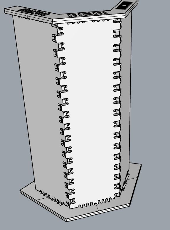
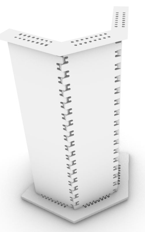
And this the result. In this case for a 45 degrees joint
And images!
The result of joint
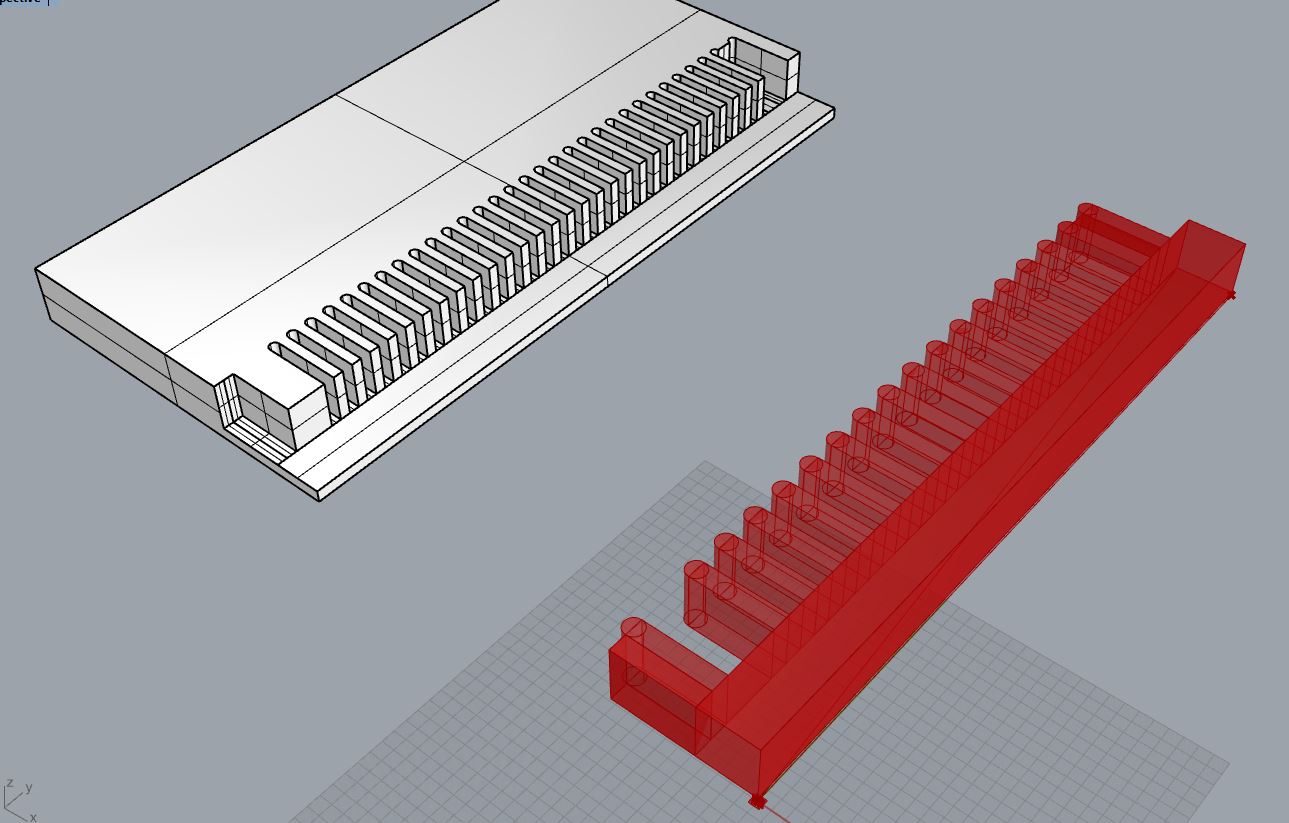
The idea it’s that the grasshopper creates a volume frome the base line and you substract it (later) from the model. So if you have a triangle you substract 3 of these, one from each size.
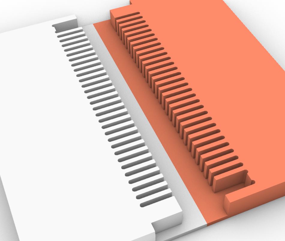
In this test I processed to Rhinoceros and make the same piece twice, rotated 180 degrees.

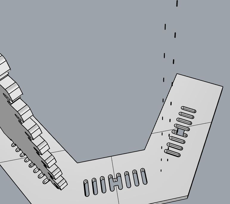
And this is how it fits.
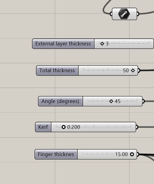
And these are the parameters you introduce
from this to the world
Notes from Edu.
The size of the wood we have it’s 15 mm. (not 50 as shown in the image)
The internal layers of the wood are 1.5 mm, so it’s better to leave at least 3 mm.
Also the fingers are 15 mm wide but could be bigger and it will be fine.
And lastly, the kerf it should be at least 0.2 mm
Next will be apply to all the model and make a version for angles from 90 to 180 degrees.
Useful links
Design files
Remember to use download link as.. to download the files.