Assembling a Six Pack Milling Machine
This docs are meant to track down useful information when assembling the project of Barcelona Fablab SPML
I’ve already made a version of it for the machine assigment with Tue Ngo that you can visit here I want to do a standar six pack.
Assembling a Barduino 2.2.1
Estimated time: 3-5 hours.
I have already assembled a Barduino 2.0 and one 2.2 (but with a bad FTDI chip) and the team of fablabbcn have developed a new version of the board. Barduino 2.2.1
They have made several improvements in the CNC shield and in the Barduino board itself.
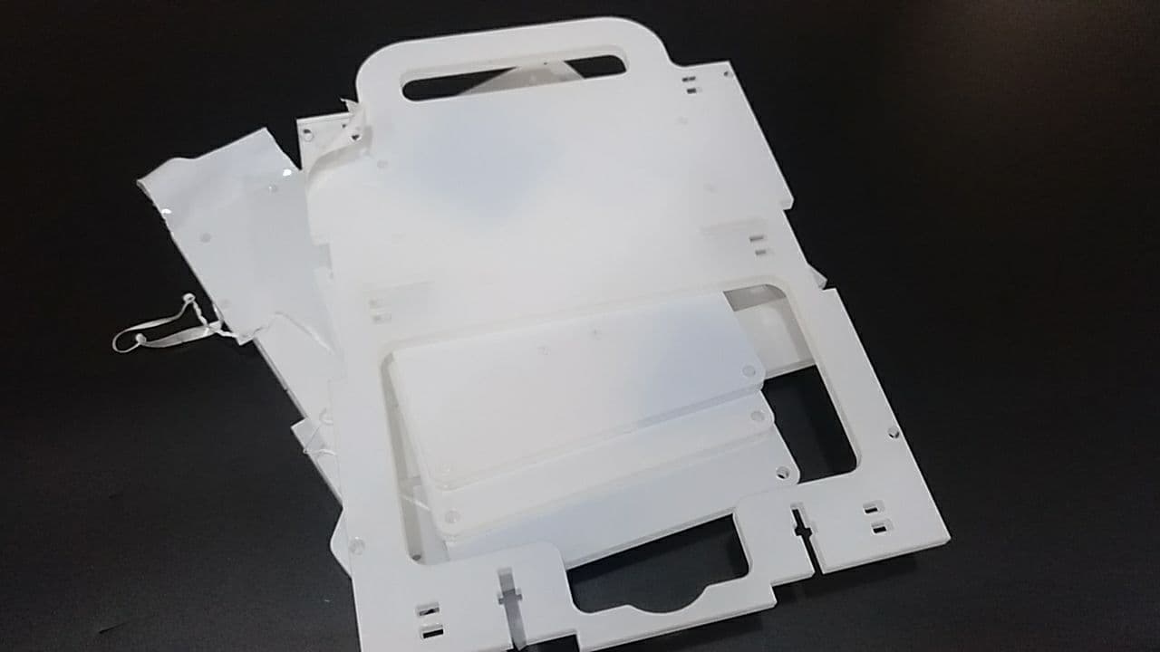
Here you can see both boards side by side (white is the newer one)
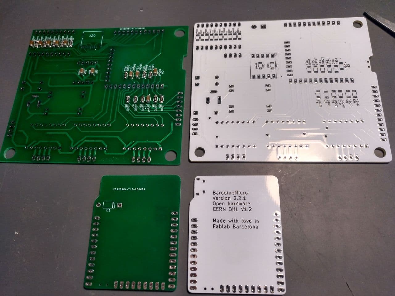
The difference I noticed:
-
Different material on the board easier to soldier.
-
New texts
-
Different position of the diode.
-
New holes to fit better the microUSB
-
Fixed a bug that required to add a jumper cable
-
Only have to soldier in one side
How to soldier the barduino 2.2.1
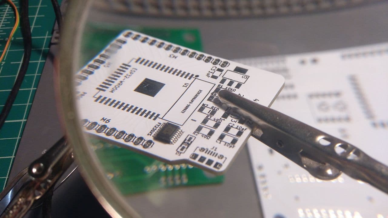
My aproximation to these kinds of boards is to first do and test the difficult component. In this case… the FTDI chip.
Soldiering the FTDI chip
Even with the improvements this chip is not easy. I need copper braid to soldier it properly.
My advice is to first soldier only one of the legs of one side, check it and soldier one of the legs of the other side. Double check if the chip is properly positioned because it might slip a bit. And it’s easier to undo 1 or 2 legs.
Then soldier and unsoldier with the copper braid as needed. And test with the multimeter the connections to check if there are no shorts and everything is connected where it should be.
To check the connections the fablab team have not yed uploaded the svg scheme and it’s more difficult to see in this board, so I used the svg file of the board 2.2.

This was the result:
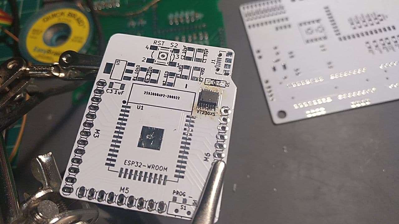
It’s a bit yellow because the soldiering time made the board yellowish.
Soldiering the MicroUSB connector
After that the next big thing for me was the MicroUSB. This was much easier to soldier than the last time.
For testing with the multimeter I used an microUSB connector to USB and check the USB connectors like this with a missed pin that I found:
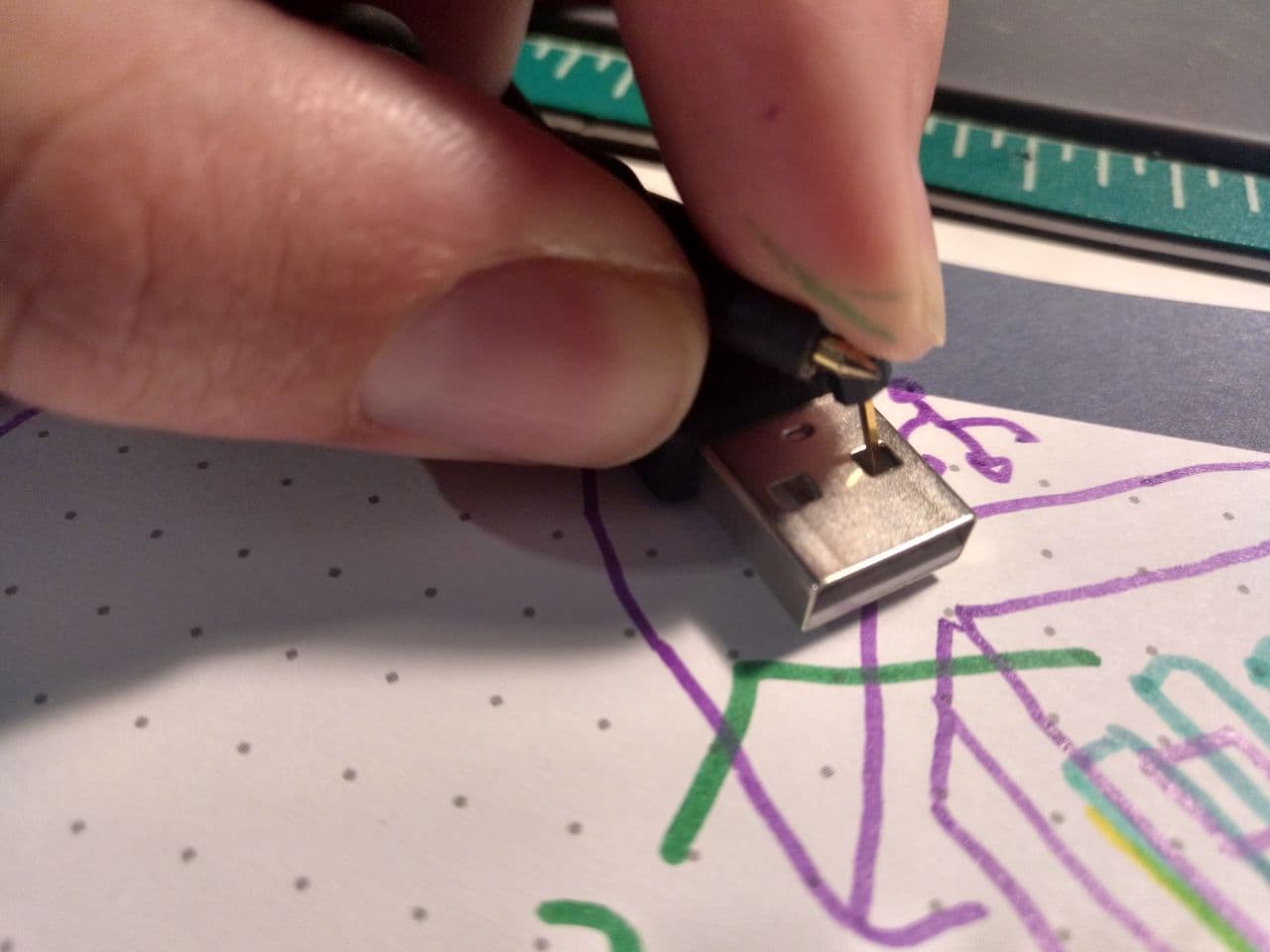
I’ve made a scheme of how it’s connected each pin of the USB to places in the barduino to check that everything is ok.
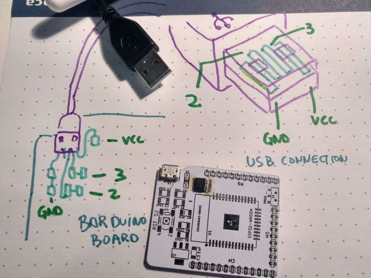
This barduino - USB scheme will be useful to anyone so they don’t have to google “USB PINOUT”
With this versions is way more easier to soldier because the connector fits and you can put it in place before soldier the traces.
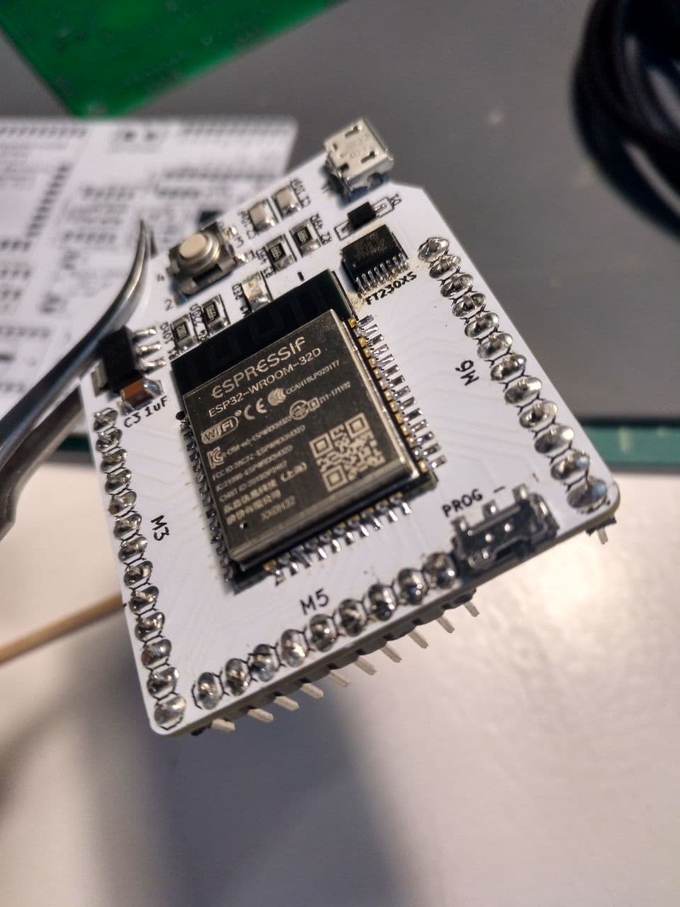
Soldiering the rest of the components
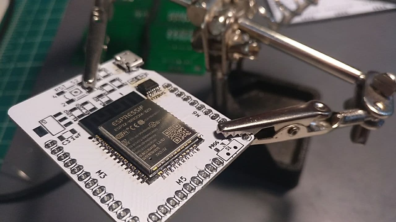
Then I go to the big chip, the ESP32. In comparasion this is pretty easy but I prefer to check that every trace is properly soldier with the multimeter and there is no shorts after soldiering this fella. The earlier you find a short the easier it is to solve!
Then I go for the shopping list to the rest of the components except for the pins. I soldier them and test if everything is ok. I upload a blink program with ArduinoIDE, setting the parameter of blinking to the pin 13. (I check if it works with the multimeter between ground and the pin13 [here the pinout of Barduino()])
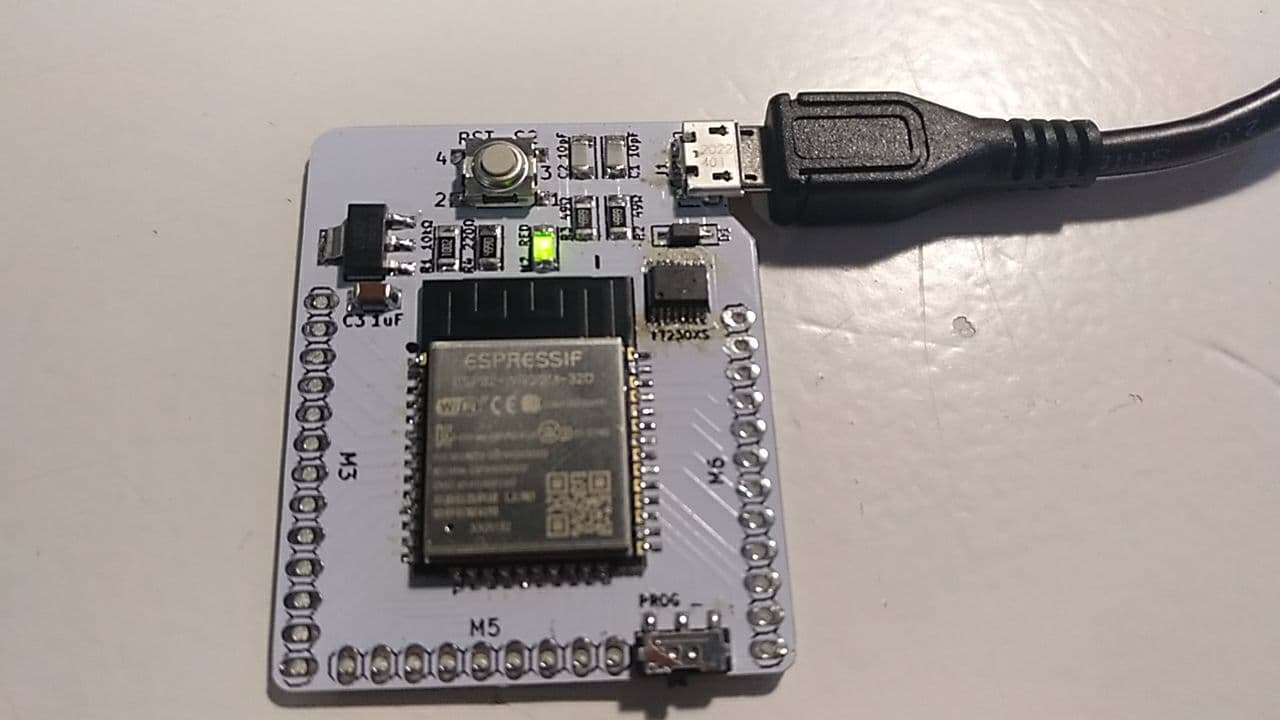
Once I see that the program uploads I continue with the pins.
And after a last check out with the multimeter I’m done!
Conclusions of the new board
It’s more usable and easier to soldier. The FTDI Chip is still difficult but there are few things that can be done about it. Improvements for the future:
- To have accesible the schema and pinout of the board like in the Barduino 2.0 is quite useful when soldiering and designing things around it. But I guess that it will come on time.
In the text layer I have a couple of suggestions
-
the “prog” tag could be improved with prog/run so it’s more clear the two positions of that switch
-
the diode drawing is confusing.
Assembling the CNC shield
Estimated time 2-4 hours + configuration
If you need files, here is the project
I’m soldiering the version 1.1
Main changes between 1.0 and 1.1
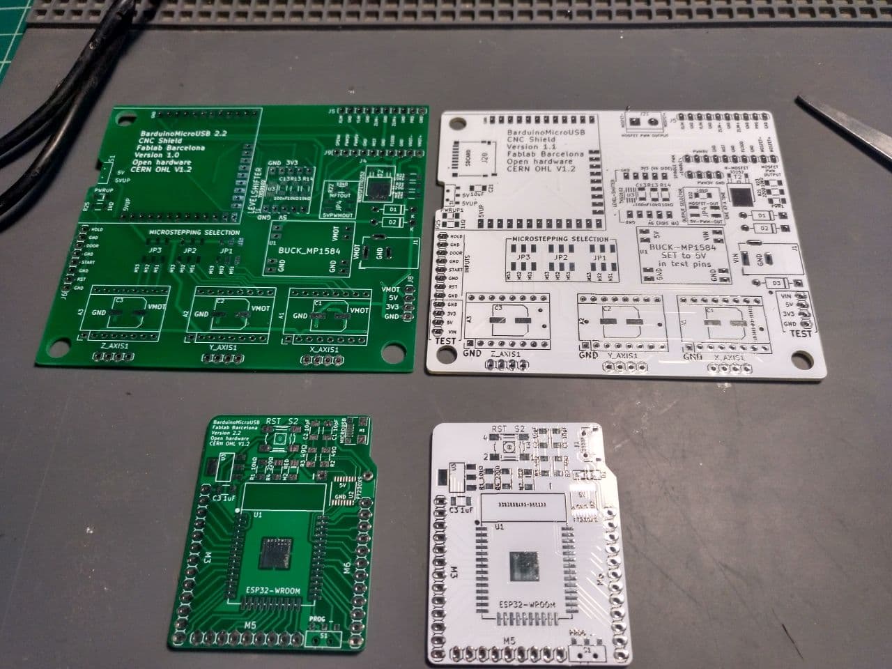
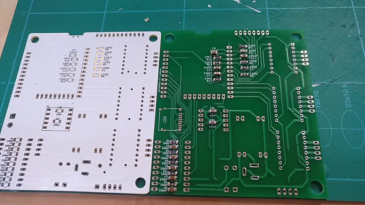
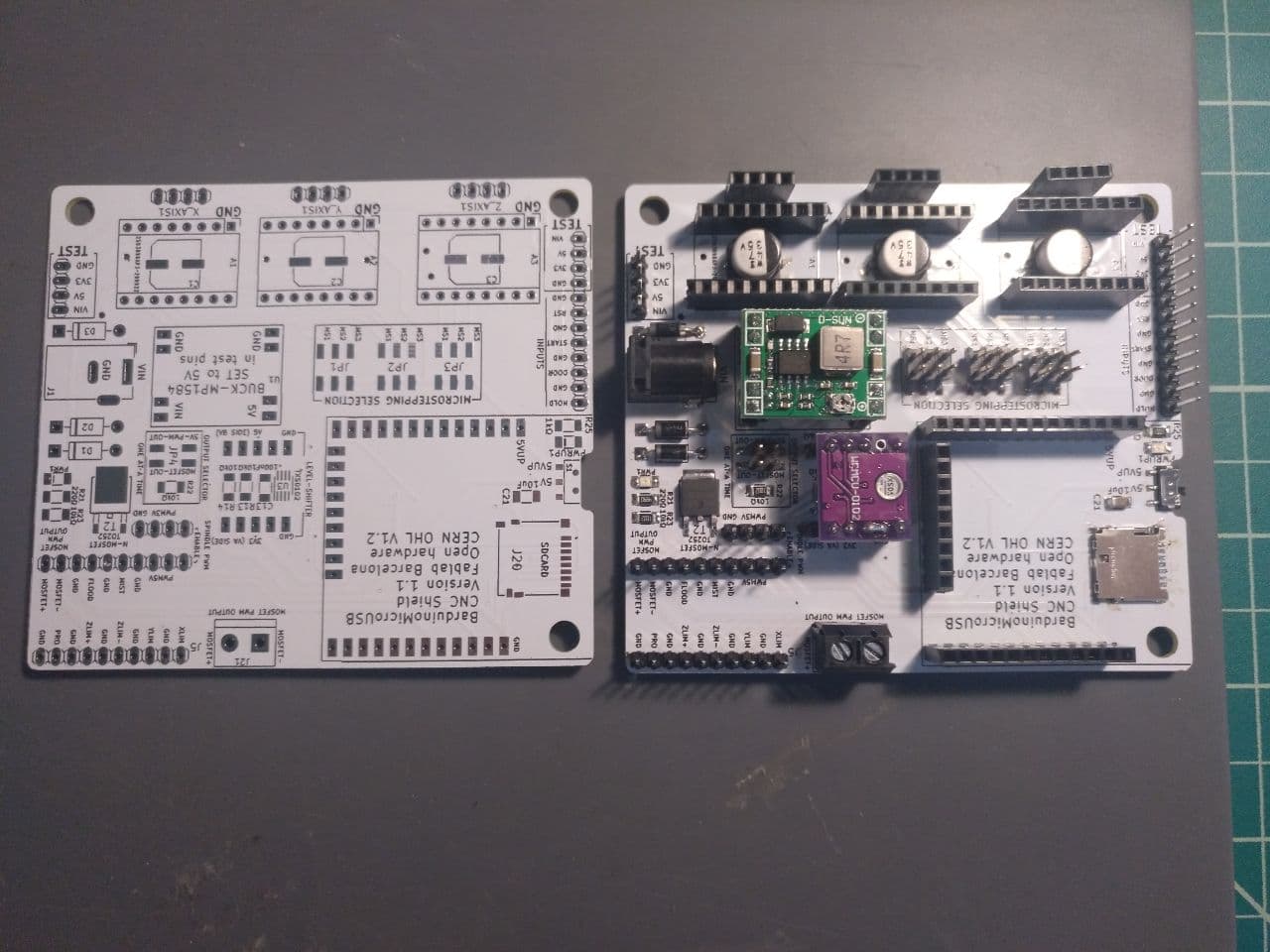
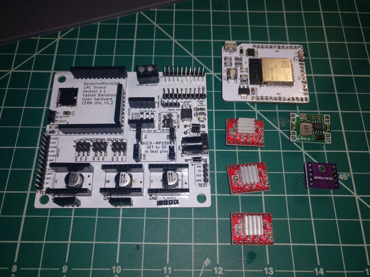
You can see the difference comparing side by side in this images. The green is the 1.0 and the white is the newer 1.1 version
front
back
-
There is a new output for the DC motor
-
The micro SD has a new position in the front of the shield and not in the back.
-
Added more test pins.
-
Changes in the texts.
How to soldier the CNC Shield
In this case since there is enough space, I’d go first for all the list of resistors and capacitors that go on top and bottom.
- Note: the resistor, capacitor and microchip of the level shifter are not required if you’re using an external level shifter like these
In this case I had those resistors and capacitors already mounted in a previous version of the CNC shield. So I had to unsoldier and soldier again. Luckily this is not a big deal.
And also I had a reference of how it has to be mounted to made things easier.
After doing that I continue with the big components
Special pieces
There are several pieces that might need some extra tips or info.
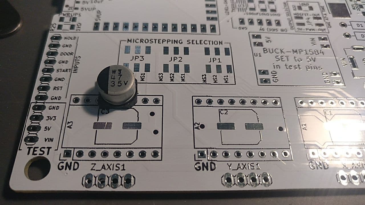
Big capacitors
Beneath the drivers for the stepper motors that control the 3 axis, there are several big capacitor that are polarized. They have a specific footprint that you can follow to soldier them properly.
Diodes
The diodes used that have long legs. You have to put the legs through, soldier and then cut the unnecessary leg.
Spindle exit
The spindle exit from the material we have in Barcelona, you have to cut one of 3 exits to have it set properly.
Level shifter
The level shifter needs a couple of touches before connecting.
There are 2 legs to be cut and two that need to be soldier together as one.
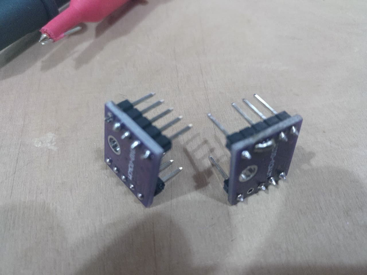
on the left the original, on the right the proper configuration
Also have in mind the position of the pins and the board. The chip goes downside.
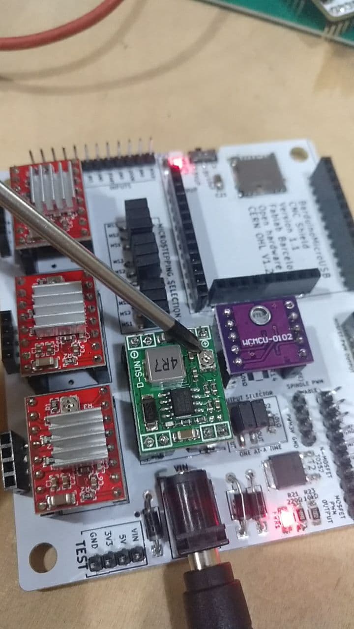
Now you would have something similar to this:
The trick of how to put lots of pinsets
This is my personal trick for all those pins that had to be soldiered in this board that have the holes and they are already connected between them.
I put some liquid metal in one of the extrem holes. I keep it liquid with the soldiering tip and with the pincers I make the pin go through until the other side. Then from the back I soldier the rest of the pins since they are already in position.
Then you will have all the parts similar to this:
Conclusions of the new CNC board
It’s way better than the other.
There are a few improvements
-
The distance between the stepper drivers is not equal. It’s something trivial but once you see you cannot unsee it.
-
Have more documentation about what does each part do. Online. I have the schematic but some png or svg could be very instructional since is harder to see were the traces are going and what does each part.
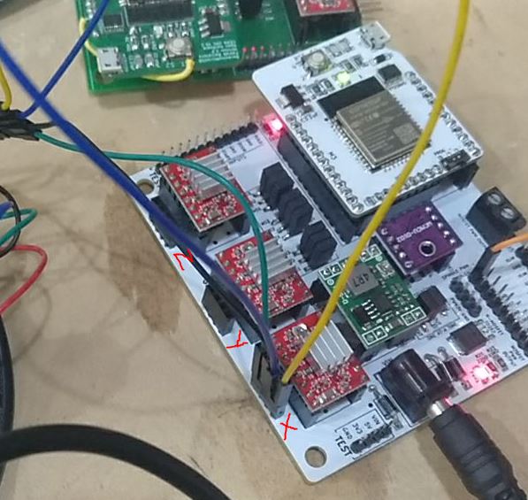
-
Put a bigger X / Y / Z labels next to each stepper (even more than once). Now the “x1_axis” is too small and it gets behind the cables. See image:
Configuring the CNC Shield
Ok, you have all the parts and now we have to configure the shield to work. There is an important step that has to be done before connecting the Barduino and another step that has to be done once the Barduino is installed and connected.
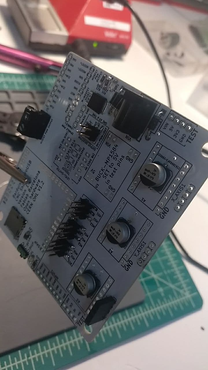
IMPORTANT, the shifter from 12 to 5 V!
The first thing is very important. Right now the input is 12V but there is a a regulator that goes to 5V. You have to set it. You’ll need to connect it and measure the voltage between the ground and the voltage you’re giving the board.
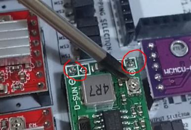
measure here between the red circles
With a screwdriver you can adjust the voltage. It should be as close as possible to 5 volts but better if you don’t surpass it (so 4.92 better than 5.03 V)
screw here
Once you did it you can connect safely the barduino and don’t burn it.
Yay.
The steppers drivers
The steppers need also configuration but for that need a barduino connected with the firmware set. If you don’t go to the firmware section first. But you will need the multimeter and the screwdriver later.
For this you need to set up a potenciometer into the right position so you make your motors move but don’t burn.
You will need to have your steper driver assembled and set in the position, the barduino running with the firmware (important) and the power should be the 12V input.
Then you can measure the voltage between the screw of the driver and ground. It’s important that has to be ground and not a pin not grounded because you can make the stepper useless fast. It happened to me.
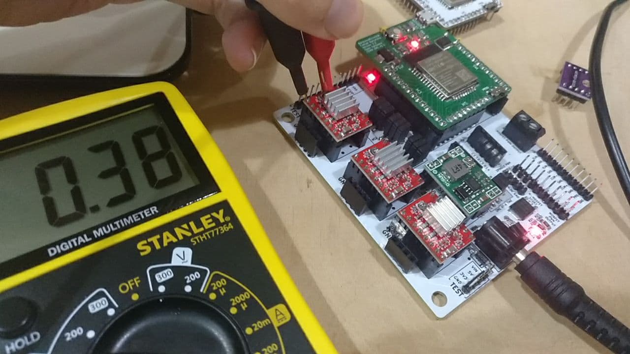
The voltage should be 0.13 V. With that the steppers should move and don’t burn themselves.
Installing the firmware
This takes between 1/2 hour to 1 hour. It takes long to compile.
This has been coverd also in my machine week here
You have to have installed arduino IDE. You need the cable (micro USB).
You have to download the repo of the sixpack firmware (Grbl)
You have to install the extra libraries needed for this project and the ESP32 boards. You should set for all the barduino projects the ESP32 Dev Module.
Then you have to set the barduino to program mode using the switch and press the reset button.
You have to open the GRBL project in barduino (there are lots of files that are already configured, you don’t have to change a line of code)
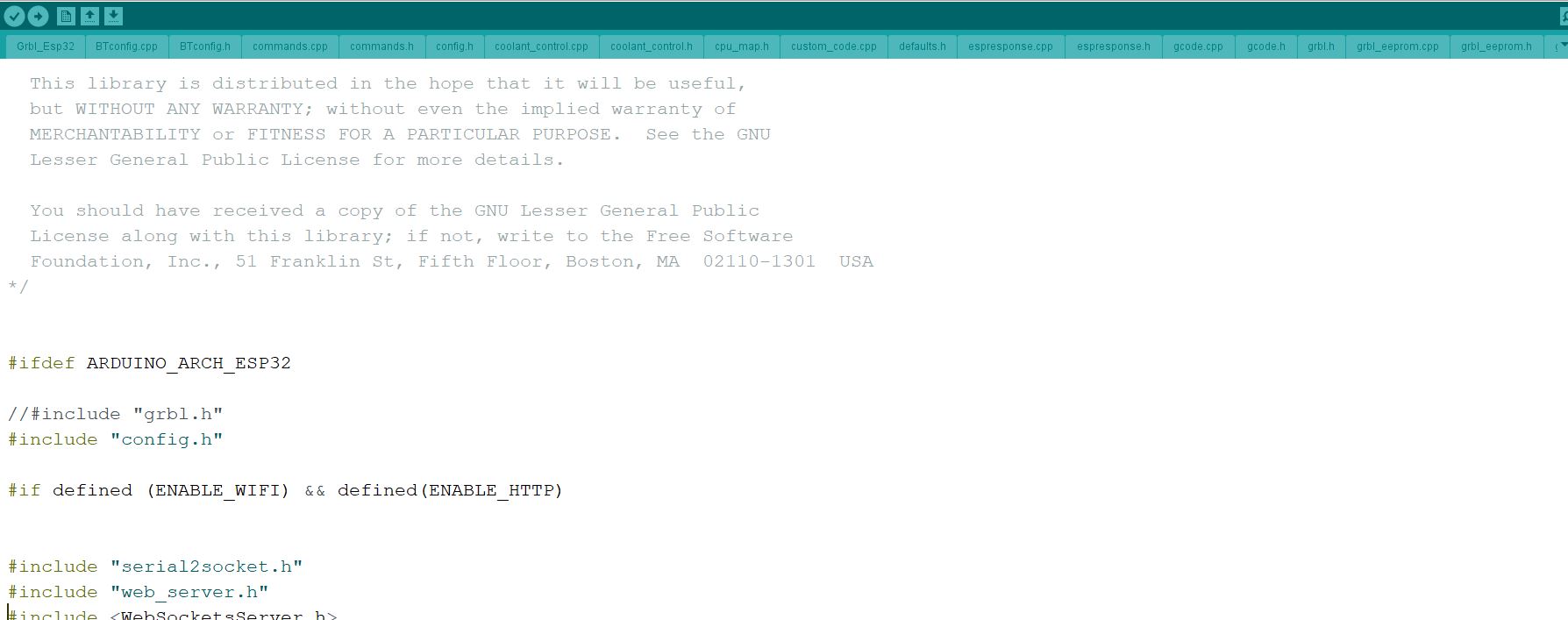
Now the last configuration is to set the memory to Minimal SPIFFS
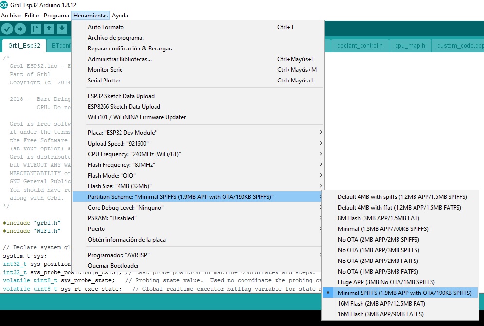
Then you can upload the code. It will take some time to compile. If it doesn’t compile it can be(probably) that:
- You miss some libraries
- You haven’t set the correct board (ESP32 Dev Module)
- You didn’t set up properly the memory usage to Minimal SPIFF (that is if the error says that there is not enough memory)
If it compiles it will try to upload the code. Things that can go wrong there:
- There is a problem with the barduino. Soldiering. Happens. A lot.
- You put the barduino in run mode and not in program mode or you didn’t reset it.
- Cable things.
- Port configurations of your computer.
If it something happens during the upload, you can try a blink program that doesn’t take 15 minutes to compile.
The compile time for this file can be long. I mean 20 minutes if you have a slow pc. The upload even in slow PCs is more less fast.
Once you connected it you can connect to the wifi set by GRBL
By default the wifi is GRBL_ESP and the code is 12345678 (Super hackable). You can change it in the future.
Connect it with your computer and the caption portal will say that misses some index.html.gz. It’s on your repo in the firmware folder, in something like “six-pack-cnc-master\firmware-grblesp32\Grbl_Esp32\data”
You drop it and now you will have it running! (not totally configured but running!)
Now you can go back and set up the stepper motors voltage to be ok. There are more configurations to set but
Mounting the Frame
2-4 hours plus fabrication.
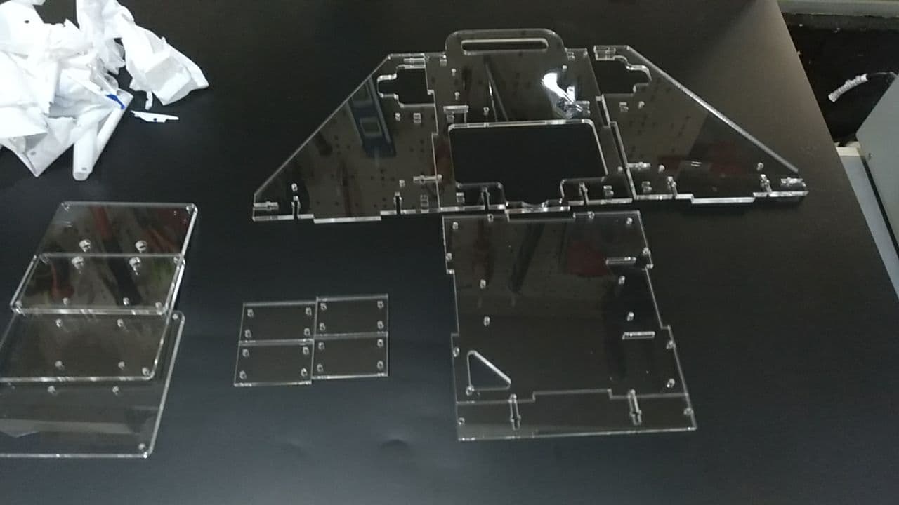
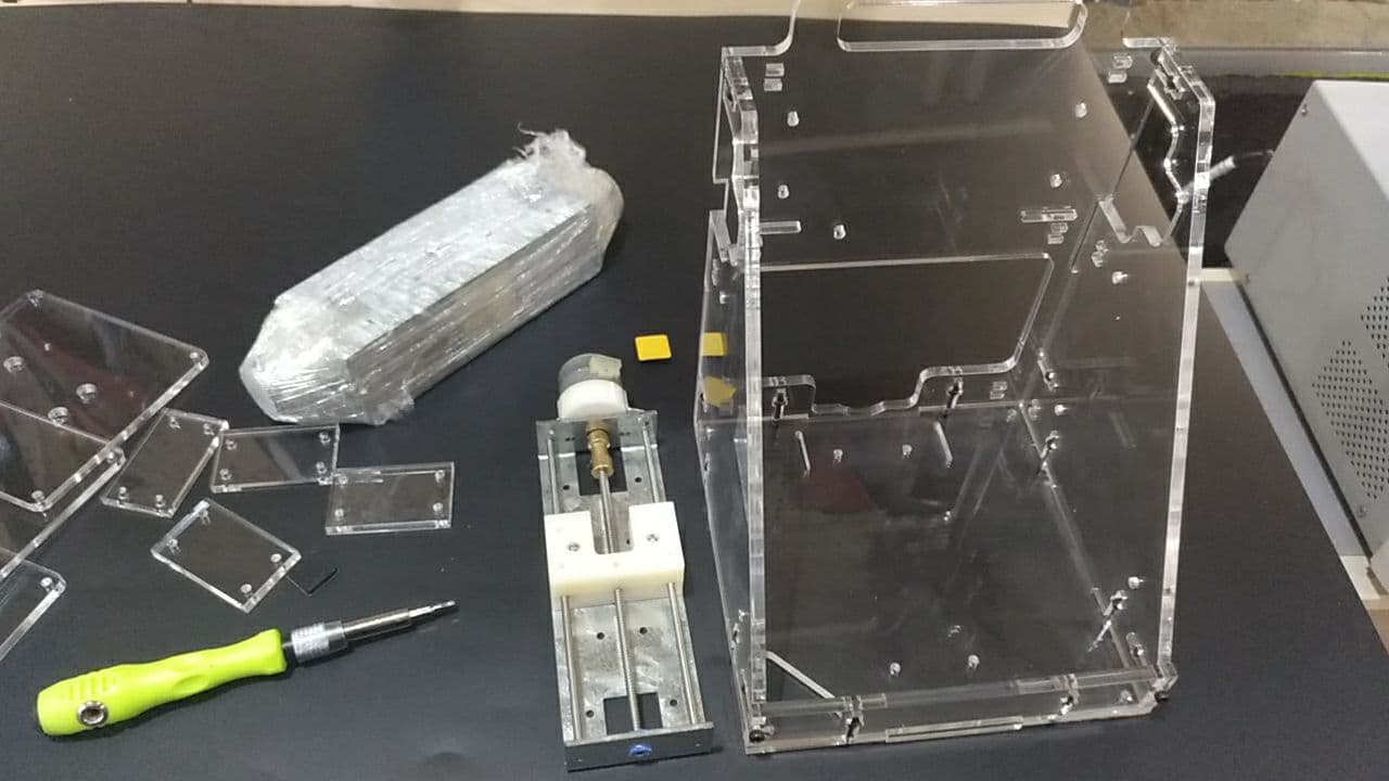
There are several frames. I used the Lasercut open. You can find it here.
So after being cut and being peeled you will have lots of pieces that go together with long 3mm screws.
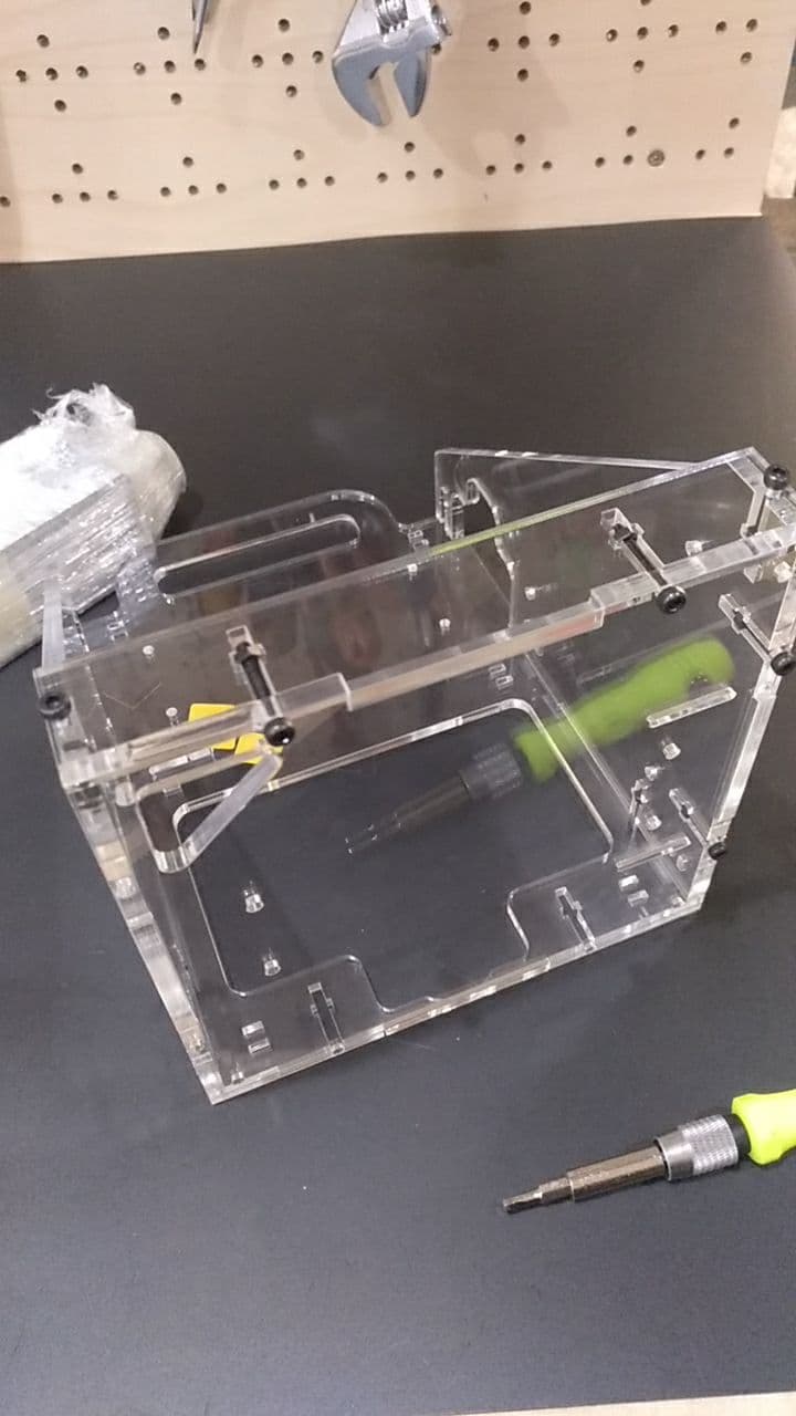
I usually set all together loosely before using the allen key to tighten them properly.
Then we add the axis. The X axis is a bit tight.
I fixed them with the same screws. Since its tight enough it holds properly.
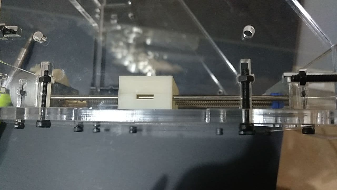
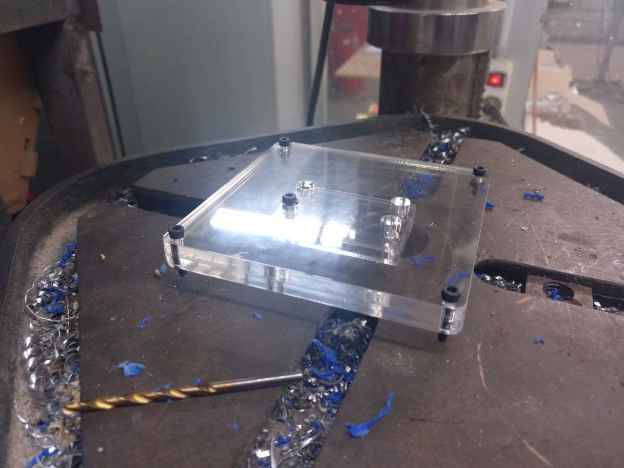
For the “table” on the x axis you will need to put together several pieces. In those versions the holes are, in the long distance 39 mm between each other. And in the axis they are 40 mm so, you have to drill a bit. With a 3 mm drilling mill you will be fine. This also aplies to the 3D printed pieces.
Then you will have something like this:
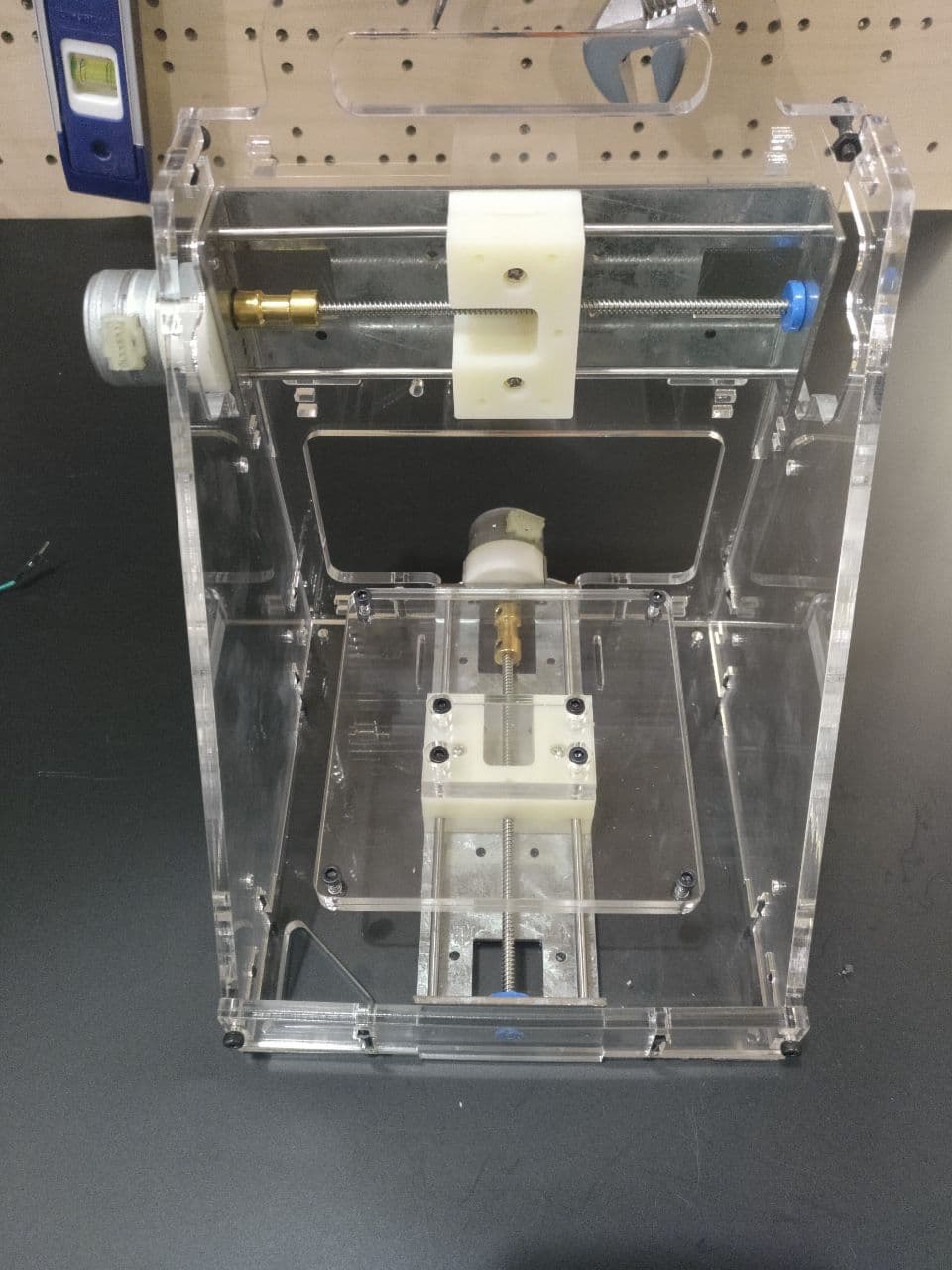
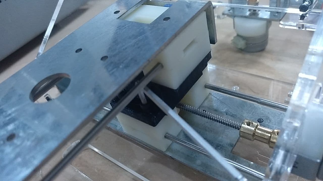
The Y-Z connection
For the light machine I did a specific version that was easier to screw with more height. The only thing is that the X plate now is not centered.
on the left with proper holes
I had a problem with the 3d printed and I still have to set properly the size of the holes. But with a drill you can get it properly fast. (3mm)
And this where it goes:
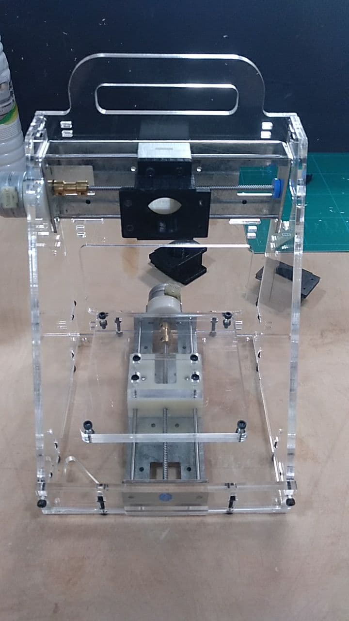
What I did was first to set on the Z axis an then into the Y axis. This makes easier to operate. I also moved the Z axis to manouver properly.
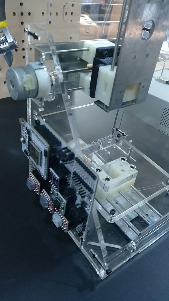
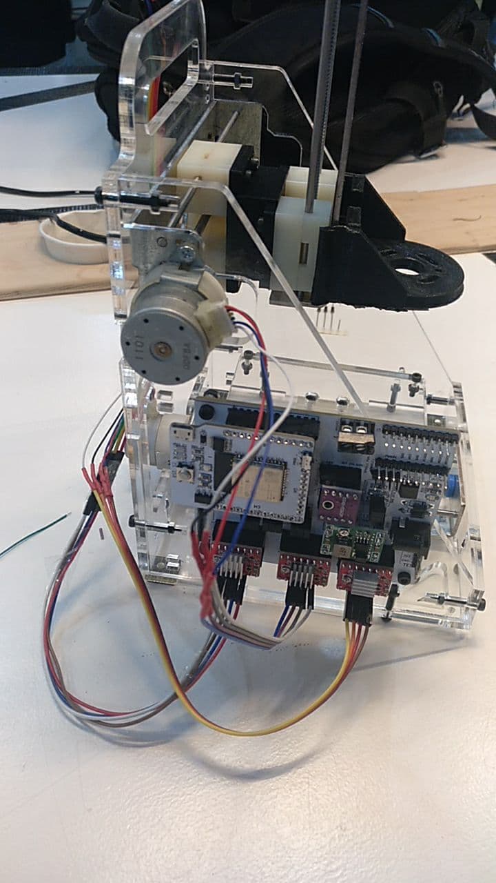
Then I screwed the CNC shield with no box because I like the transparent gameboy.
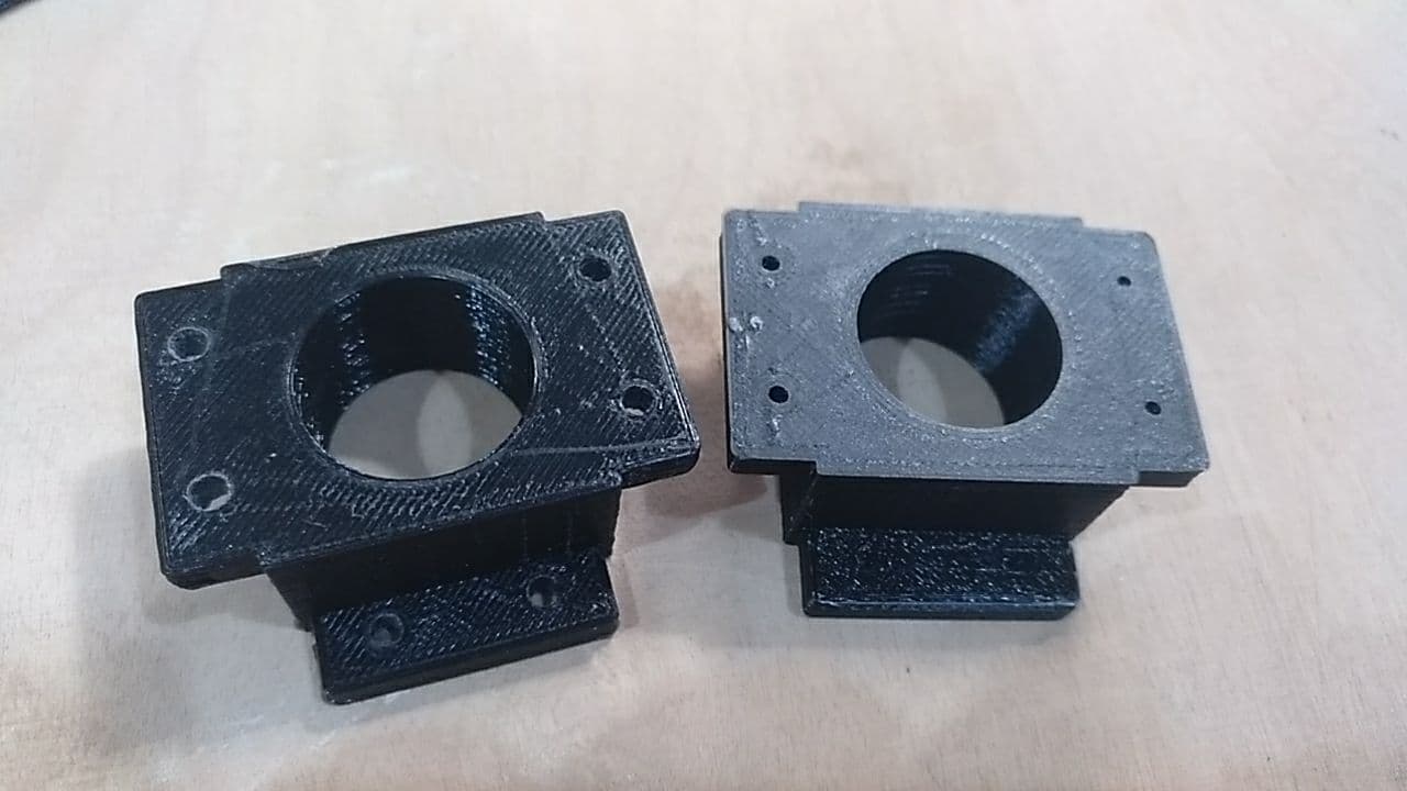
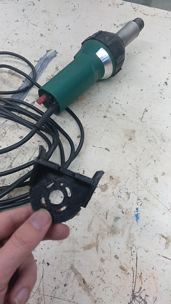
I also 3d printed the holder of the Spindle but I had to use the heat gun to fold it a bit to make it fit.
Cables to the axis
[you can see another version of this here in the Machine week]
So we have these six connectors
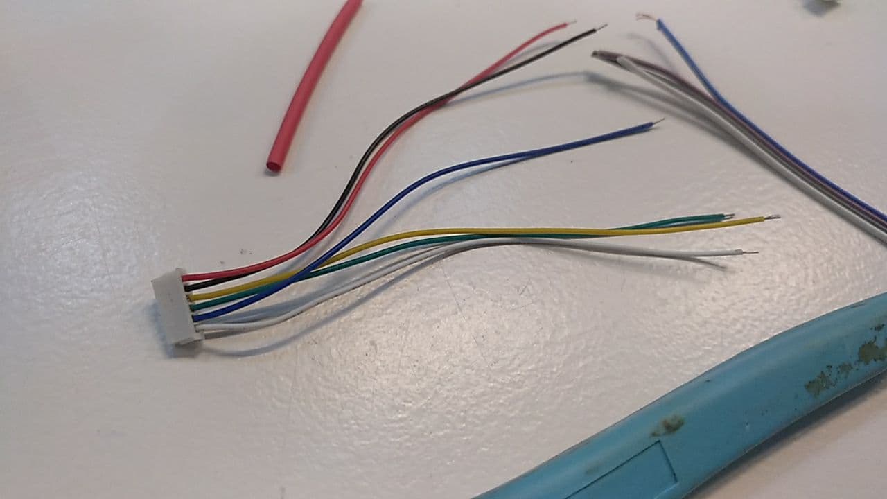
And we have only 4. connectors.
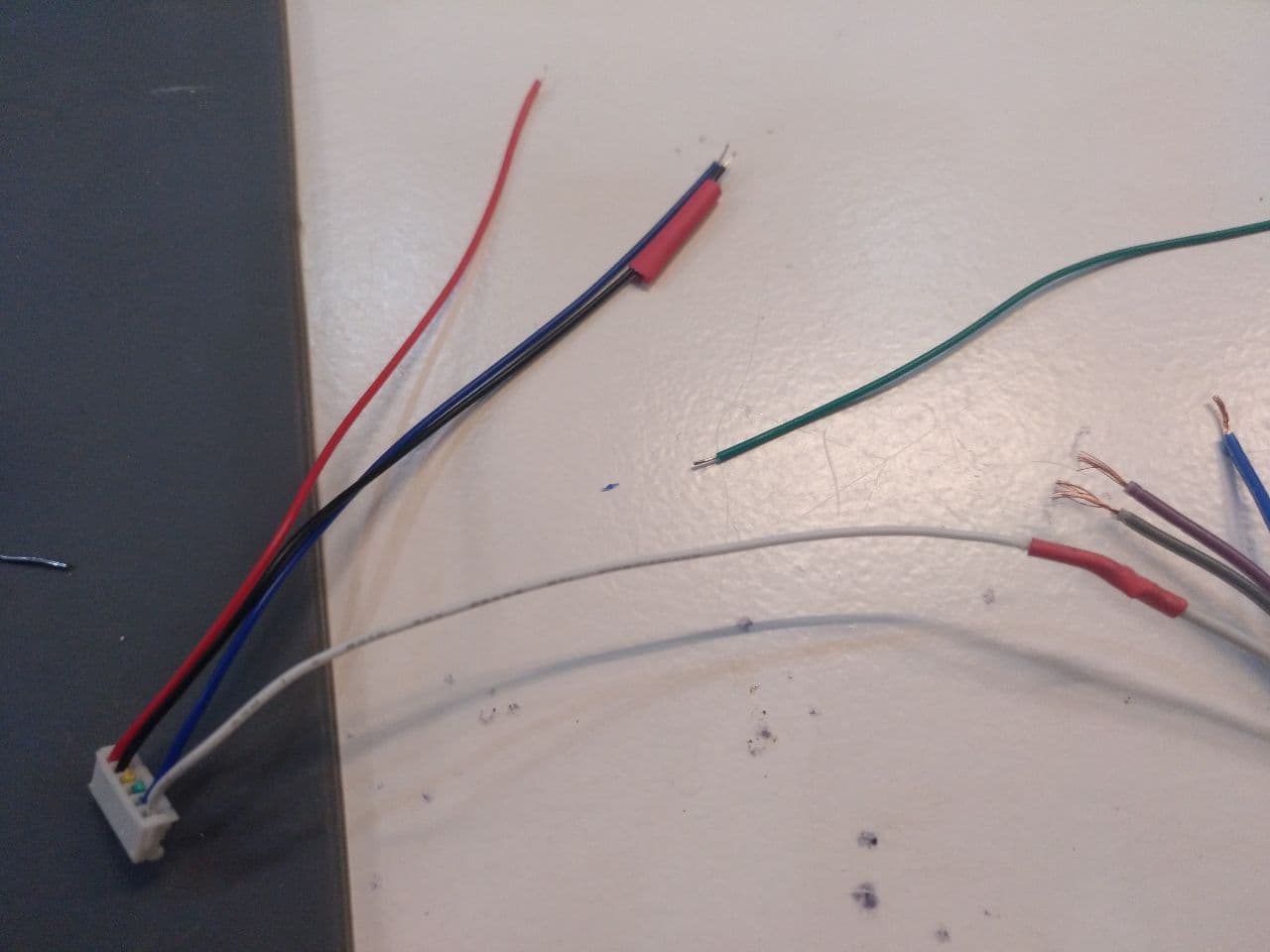
The short answer. You can take out the green and the yellow cable (in the middle) and you have to connect in this order: white - black - blue - red.
If posible, try to not put all the cables in together so you can rearrange them if needed.
These cable are very short so you will need to extend them. For that I’m soldiering and using heat shrink tubes to keep them in position (and without making a short)
First you have to put the tube like this
less cable
Then soldier the 2 extremes together an then slide the tube and with a lighter or the soldiering tip you can shrink it and tada!
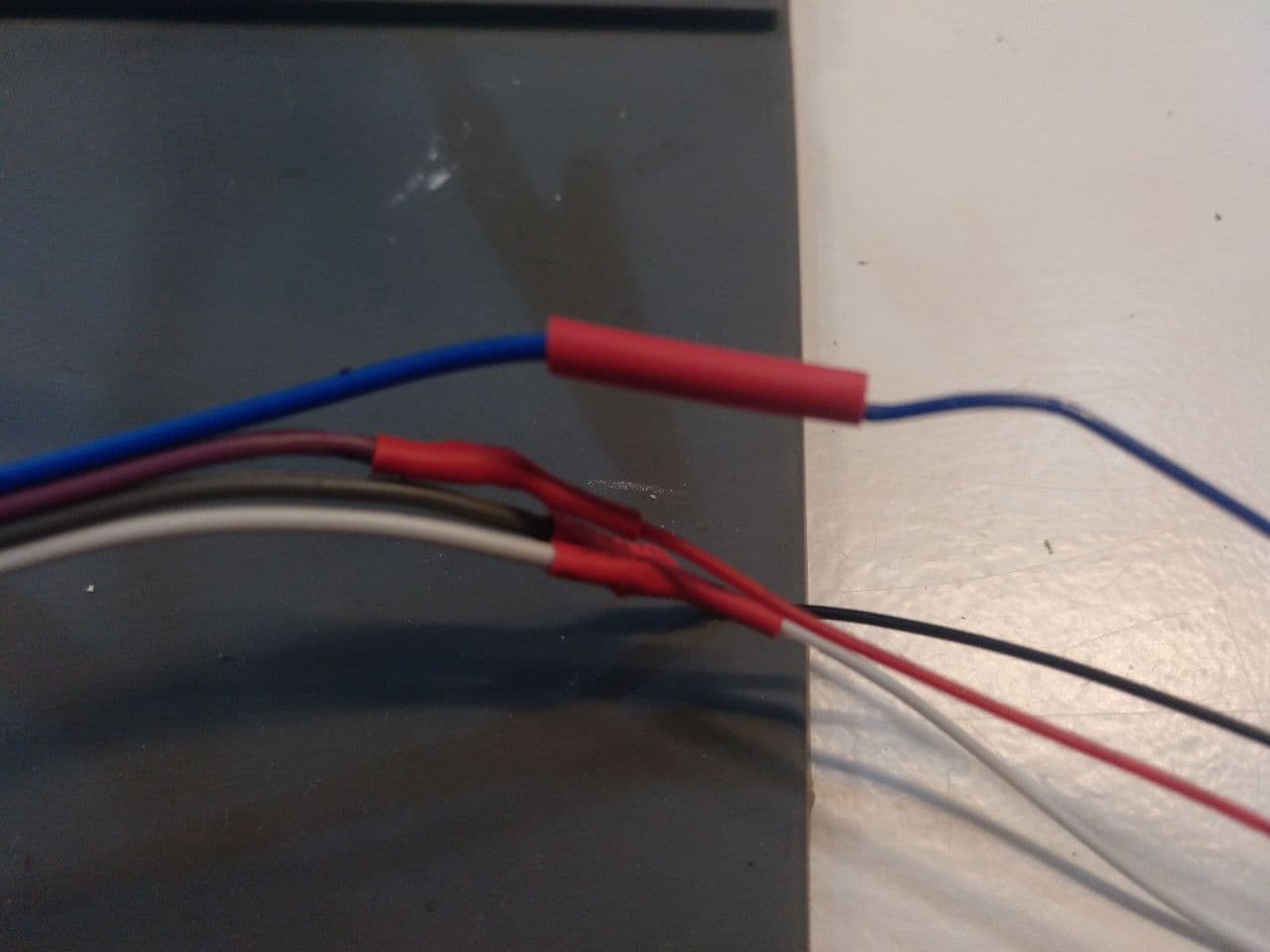
the blue is not yet shrunk, but the others are
If you forget to put the tube before soldiering the 2 cables together you can undo the soldiering or forget about the tube. choices
Now you have the first cables in your SPML (apart from the power supply)
And you can test the motors and check if they move.
Setting the axis movement
Now we have to set the steppers inside the GRBL.
We have to access it (something that we already should), go to the GRBL configuration table and press update.
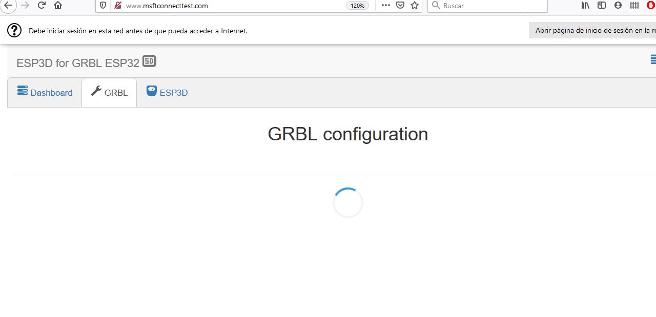
You will see this table.
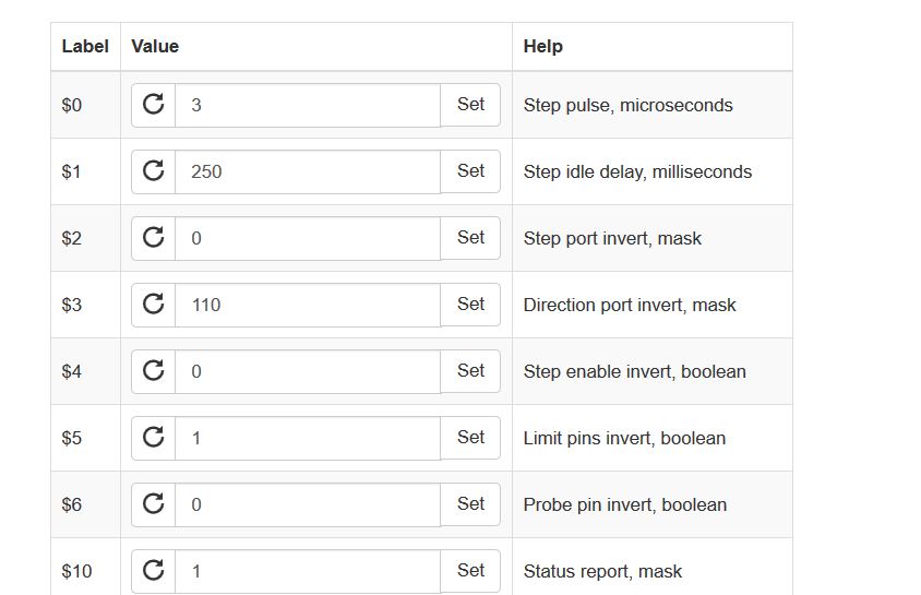
In this table you have to change this value to test the motors:
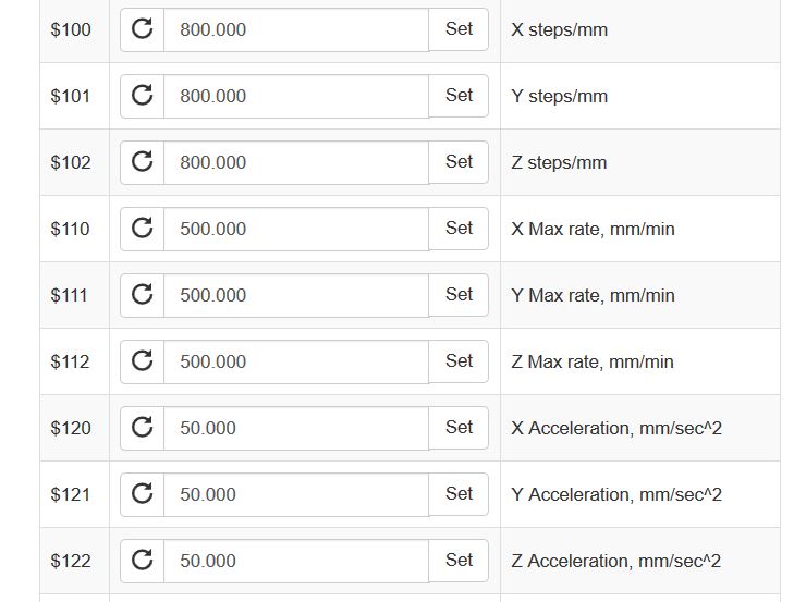
There are more to configure but with this should be fine to know if the motors move or not. To do that you can use the phone or the computer and the wheel to check it out. Remember to move in 1 or 10 mm but not in 100 mm. (it will be slow and over the limits of the machine)
Posible problems with the motors
If there are problems with the motors can be that
-
The VREF is not properly set.
-
The wires are not arranged properly. (maybe you have to change two by two)
-
The stepper driver is fried because you melt it when measuring the VREF (happens).
-
The motor itself doesn’t work (not happened to me yet, but it’s a possibility)
-
The screw of the axis is not properly set.
-
there is any kind of problem in the cable connection.