17. Machine design
Ok, for this week this is going to take a little longer because we still don’t have lab access. But we do as we can. I teamed in this case with Tue
You can see her documentation here
Here is the group page that combines both pages here
This is what we’ve got by now:
Concept
We are planning a 3D light drawing machine so it makes movements in 3D that you can capture with a camera. The idea it’s to use the same boards (+ a few things) of the CNC machine.
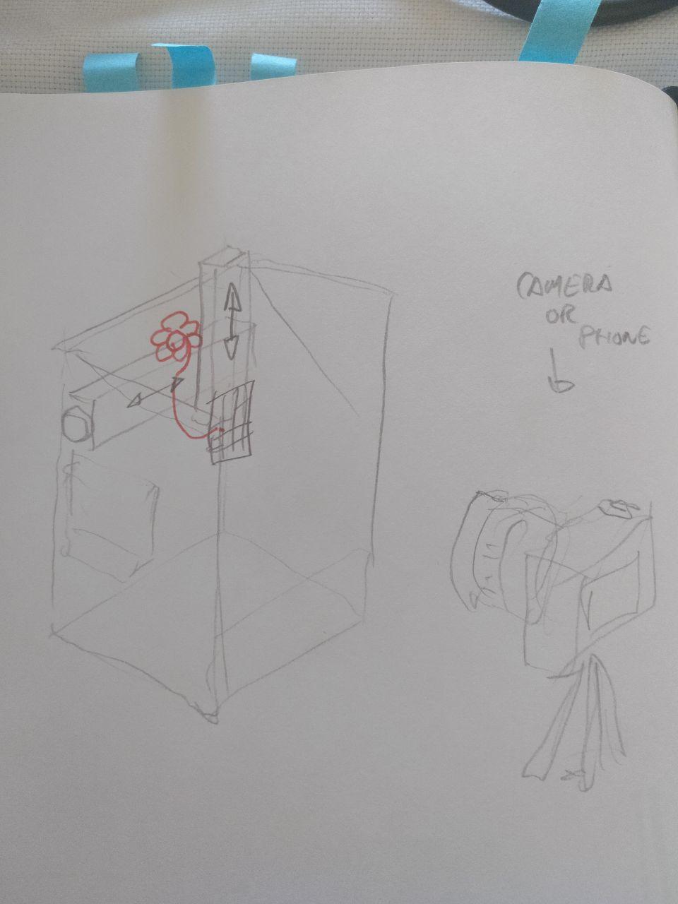
First sketch
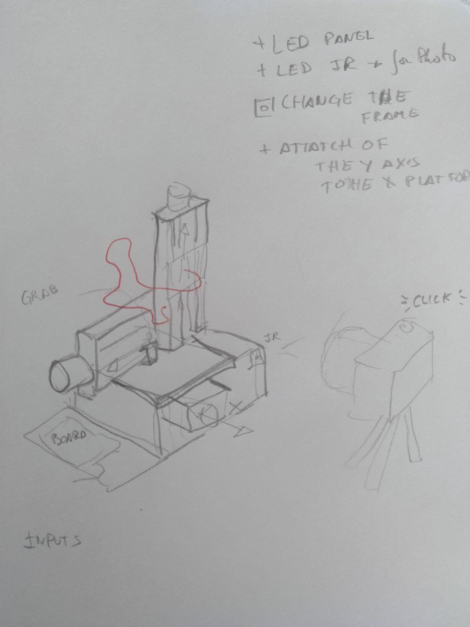
Second sketch
Understanding the SPML

Ok, we have this git reppository to investigate. The readme is extensive and clarifying, but I need to dig up a little more to know how to tinker it.
We have arrived to the point of netrunner references
There are 2 main boards
The first one it’s a version of Barduino (and ESP32 board that we have already work with). In this case with a microUSB connection. You can see the full project here
If you want to work with them from Arduino IDE you will need these libraries:
http://arduino.esp8266.com/stable/package_esp8266com_index.json
https://raw.githubusercontent.com/espressif/arduino-esp32/gh-pages/package_esp32_index.json
https://dl.espressif.com/dl/package_esp32_index.json
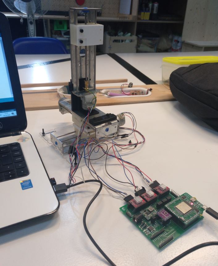
The other one it’s a shield connected to the barduino. You can see it here

the barduino goes up on the left
On top of the shield there is also the boards for the drivers of the stepper motors (one for each axis)
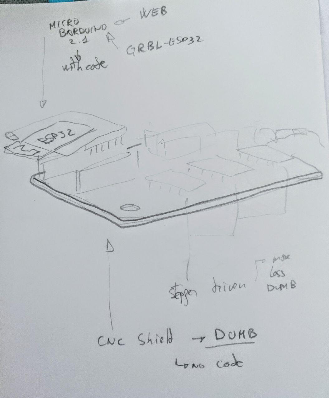
This is a drawing showing the scheme. For those unfamiliar, the shield doesn’t hold any microcontroller, it just routes and connects different components.
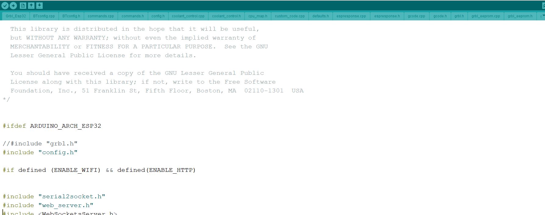
For driving this ESP32, It’s commanded by a firmware called Grbl_Esp32. That’s a GCODE parser. You can see it here but adapted to the firmware of the ESP32 microcontrollers (such as barduino)
This Grbl_Esp32 it’s an implementation of that it’s kind of… tricky to install, at least for what they say in their wiki
The code you have to upload it’s tangled (or untagled) in several files, includes and cpp files.[ You can see them in this folder](https://gitlab.com/fablabbcn-projects/cnc-machines/six-pack-cnc/-/tree/master/firmware-grblesp32/Grbl_Esp32(. That come from the GRBL library (at least judging for the commentary on the ino file)
It also includes the webpage already done. That’s cool.
Now the questions I still have:
-
How do I translate GCODE into easy output things (such us switch on/off a LED)
-
How do I change the X, Y and Z. Where is the config table/file for that?
-
If we want to use Marlin instead of GRBL (because they told us that they allow more things with LEDs) how do I change it?
Understanding GBRL
GBRL is a parser and can be pronounced however you feel it as they say in their wiki
It’s supposed to work with a computer via serial (or another way), usually not standalone.There are several programs. They’ve told me about candle and another one called Universal GCODE sender.
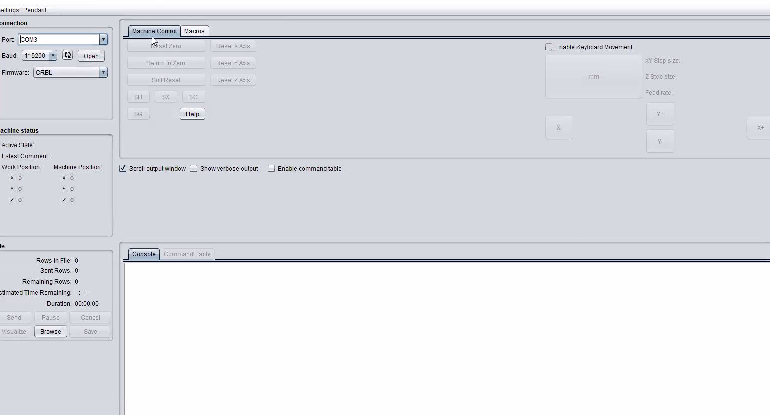
this is how they look like
In this case the project uses a webpage (already made by someone else, all in one big .html file).
They also told where are the main configurations of the machine.
Configurating GBRL (And changing it)
There are 2. The first it’s what you embed in the sketch. But also the first time you swithon the machine there are several configurations. Let’s go with those first:
They’re explained properly here but in summary:
You connect the machine and you get the webpage. Then there is a terminal where to put some commands. They all start by “$”. Each of them it’s a configuration command. And they’re written in the memory so if you unplug the machine they’re stored.
The most important/common are these ones:
$100=250.000    X steps/mm
$101=250.000    Y steps/mm
$102=250.000    Z steps/mm
$110=500.000    X Max rate, mm/min
$111=500.000    Y Max rate, mm/min
$112=500.000    Z Max rate, mm/min
$120=10.000     X Acceleration, mm/sec^2
$121=10.000     Y Acceleration, mm/sec^2
$122=10.000     Z Acceleration, mm/sec^2
$130=200.000    X Max travel, mm
$131=200.000    Y Max travel, mm
$132=200.000    Z Max travel, mm
at least they use metric system
The second part it’s the machine configuration. So we can go under the hood and try to explore the configurations. There are several files of configuration. If you want to navigate these files it’s better to download or clone the repository and open it with any text editor that allows you to browse folders.
Luckily most of the configuration it’s pretty well commented so if you touch something there is a huge block of text saying what you’re touching.
The .ino it’s the “main” file and it calls to other files (.cpp or .h) each of then encapsulates a specific portion of the code.
So let’s go to the config.h where there are some configurations, but most of them are included in machine.h. That files calls for /machine/spml.h (six pack milling machine)
There we can find this:
#define MACHINE_NAME            "SixPackMachineLab"

#define X_STEP_PIN              GPIO_NUM_12
#define X_DIRECTION_PIN         GPIO_NUM_14
#define Y_STEP_PIN              GPIO_NUM_27
#define Y_DIRECTION_PIN         GPIO_NUM_26
#define Z_STEP_PIN              GPIO_NUM_33
#define Z_DIRECTION_PIN         GPIO_NUM_32

#define LIMIT_MASK              B111
#define X_LIMIT_PIN             GPIO_NUM_17
#define Y_LIMIT_PIN             GPIO_NUM_16
#define Z_LIMIT_PIN             GPIO_NUM_23

// OK to comment out to use pin for other features
#define STEPPERS_DISABLE_PIN    GPIO_NUM_25

#define SPINDLE_PWM_PIN         GPIO_NUM_2   // labeled SpinPWM
#define SPINDLE_ENABLE_PIN      GPIO_NUM_22  // labeled SpinEnbl
#define MIST_PIN                GPIO_NUM_21  // labeled Mist
#define FLOOD_PIN               GPIO_NUM_8  // labeled Flood
#define PROBE_PIN               GPIO_NUM_15  // labeled Probe

#define CONTROL_SAFETY_DOOR_PIN GPIO_NUM_39  // labeled Door,  needs external pullup
#define CONTROL_RESET_PIN       GPIO_NUM_35  // labeled Reset, needs external pullup
#define CONTROL_FEED_HOLD_PIN   GPIO_NUM_36  // labeled Hold,  needs external pullup
#define CONTROL_CYCLE_START_PIN GPIO_NUM_34  // labeled Start, needs external pullup
So this is the place of where you can put one pin or other to do things.
Now what if we want to send something in the infrared or light a LED?
I think I need to set up a M50 S1 it seems that it’s not supported. In the last part of the gcode.cpp we can find this:
Not supported:

- Canned cycles
- Tool radius compensation
- A,B,C-axes
- Evaluation of expressions
- Variables
- Override control (TBD)
- Tool changes
- Switches

(*) Indicates optional parameter, enabled through config.h and re-compile
group 0 = {G92.2, G92.3} (Non modal: Cancel and re-enable G92 offsets)
group 1 = {G81 - G89} (Motion modes: Canned cycles)
group 4 = {M1} (Optional stop, ignored)
group 6 = {M6} (Tool change)
group 7 = {G41, G42} cutter radius compensation (G40 is supported)
group 8 = {G43} tool length offset (G43.1/G49 are supported)
group 8 = {M7*} enable mist coolant (* Compile-option)
group 9 = {M48, M49} enable/disable feed and speed override switches
group 10 = {G98, G99} return mode canned cycles
group 13 = {G61.1, G64} path control mode (G61 is supported)
Meh.
Tomorrow I’ll continue so if see something more helpful.
Tue suggested (and sent me a couple of links such Marlin Kimbra and a long video comparing Marlin and GRBL). Marlin in 1.1 version does not support ESP32 devices, but 2.0 does! (with some limitations)
Understanding Marlin
Ok, remember Girbel(GBRL)? Marlin it’s also another implementation of the same thing. It’s a parser of GCODE. In this case it’s more specific and works on 3Dprinters and supports more GCODE commands than GRBL. Since we don’t want to make a CNC maybe we can use the Marlin firmware!
So let’s have a look.
Marlin as GRBL has a bunch of files. Last Friday Edu told me that Marlin was mor painful to configure (when you need 5 minutes in GRBL with Marlin can take longer)
To do this as I did with the GRBL, I downloaded the framework from the github and opened it with a text editor with folder capabilities.
Ok, here we have a main “Marlin.ino” and we have a couple of BIG config files (configuration.h and configuration_adv.h). And also several folders (in this I think that Marlin it’s a bit more organized than GRBL-40-files-on-the-root-folder, but that’s just an impression)
Ok, I found this in the line 2217 of the configuration.h about LED.
/**
 * RGB LED / LED Strip Control
 *
 * Enable support for an RGB LED connected to 5V digital pins, or
 * an RGB Strip connected to MOSFETs controlled by digital pins.
 *
 * Adds the M150 command to set the LED (or LED strip) color.
 * If pins are PWM capable (e.g., 4, 5, 6, 11) then a range of
 * luminance values can be set from 0 to 255.
 * For Neopixel LED an overall brightness parameter is also available.
 *
 * *** CAUTION ***
 *  LED Strips require a MOSFET Chip between PWM lines and LEDs,
 *  as the Arduino cannot handle the current the LEDs will require.
 *  Failure to follow this precaution can destroy your Arduino!
 *  NOTE: A separate 5V power supply is required! The Neopixel LED needs
 *  more current than the Arduino 5V linear regulator can produce.
 * *** CAUTION ***
 *
 * LED Type. Enable only one of the following two options.
 *
 */
//#define RGB_LED
//#define RGBW_LED

#if EITHER(RGB_LED, RGBW_LED)
  //#define RGB_LED_R_PIN 34
  //#define RGB_LED_G_PIN 43
  //#define RGB_LED_B_PIN 35
  //#define RGB_LED_W_PIN -1
#endif

// Support for Adafruit Neopixel LED driver
//#define NEOPIXEL_LED
#if ENABLED(NEOPIXEL_LED)
  #define NEOPIXEL_TYPE   NEO_GRBW // NEO_GRBW / NEO_GRB - four/three channel driver type (defined in Adafruit_NeoPixel.h)
  #define NEOPIXEL_PIN     4       // LED driving pin
  //#define NEOPIXEL2_TYPE NEOPIXEL_TYPE
  //#define NEOPIXEL2_PIN    5
  #define NEOPIXEL_PIXELS 30       // Number of LEDs in the strip, larger of 2 strips if 2 neopixel strips are used
  #define NEOPIXEL_IS_SEQUENTIAL   // Sequential display for temperature change - LED by LED. Disable to change all LEDs at once.
  #define NEOPIXEL_BRIGHTNESS 127  // Initial brightness (0-255)
  //#define NEOPIXEL_STARTUP_TEST  // Cycle through colors at startup

  // Use a single Neopixel LED for static (background) lighting
  //#define NEOPIXEL_BKGD_LED_INDEX  0               // Index of the LED to use
  //#define NEOPIXEL_BKGD_COLOR { 255, 255, 255, 0 } // R, G, B, W
#endif
With that I can follow the track. They’re implemented on src\feature\leds\leds.cpp
Also it seems that we have to add to the board.h (pins/esp32/ESP32.h) something like this
#define RGB_LED_R_PIN  12 // I don't know which pin but that's a number
#define RGB_LED_G_PIN  13 // I don't know which pin but that's a number
#define RGB_LED_B_PIN  14 // I don't know which pin but that's a number
Also I found the neopixel feature.
Now the doubts to ask the instructors (on Tuesday)
-
Should we try to implement Marlin or modify Girble (GRBL)?
-
If we implement Marlin, the part of the webpage would be affected?
But for now I guess that we have a couple of leads. And we should also make other parts of the machine.
Making a new frame
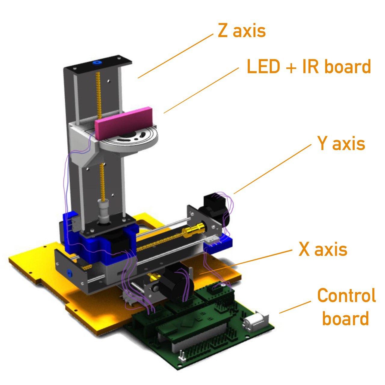
Luckily, the instructors made a detailed model of the SPML with all the main pieces of it. So now let’s try to tweak it.
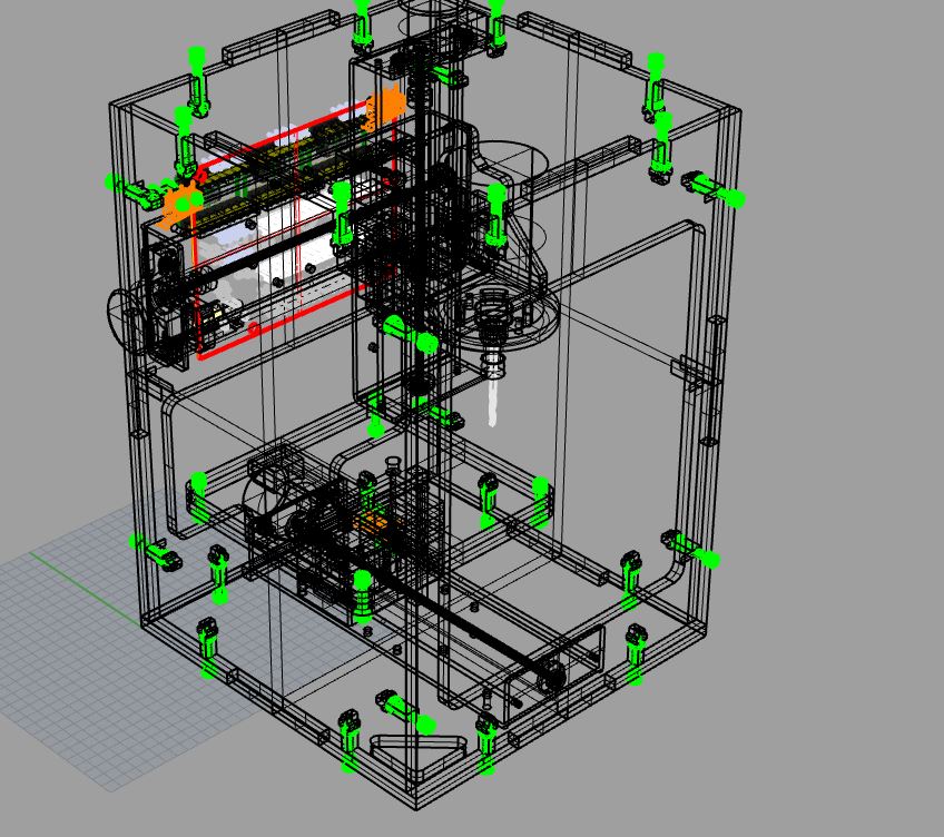
Thanks Edu! This is very useful!
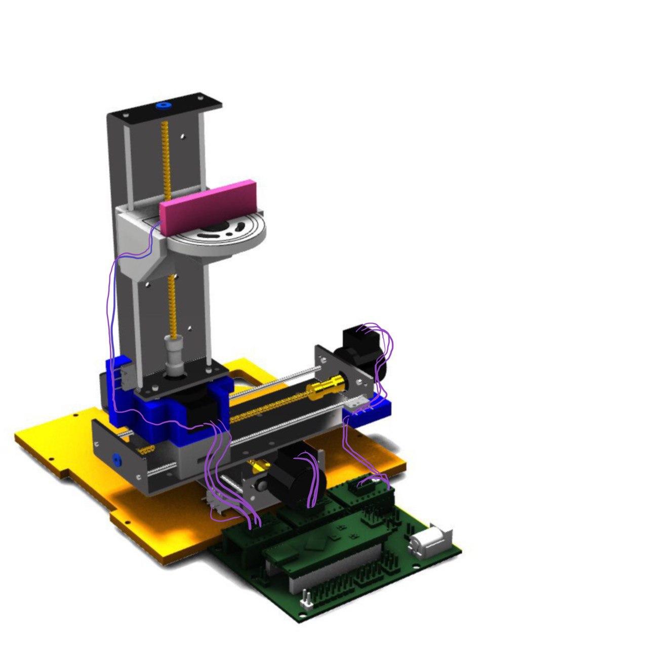
I took over all the frames because to move a LED panel you don’t need something as sturdy as if you have a spindle. I keep the bottom one because it has the X homing switch holder.
Then I realized that if we kept the platform, we would need anyway another piece to adapt the Y axis, so I just put it on top because the holes seemed to match (From the model and from the photos of aliexpress)
I added a draft of a piece to hold the Y axis homing switch that it will be developed later.
Then To add the Z axis on top of it I thought that all the motor should have the same direction to the control board (right now on the table) and I added a draft of a piece to hold from the Y axis the Z axis (to the holes it has and mount also the motor and let the cable go out)
I kept the spindle holder because it can be useful and mounted on it the board that will be used to display the LED and the IR.
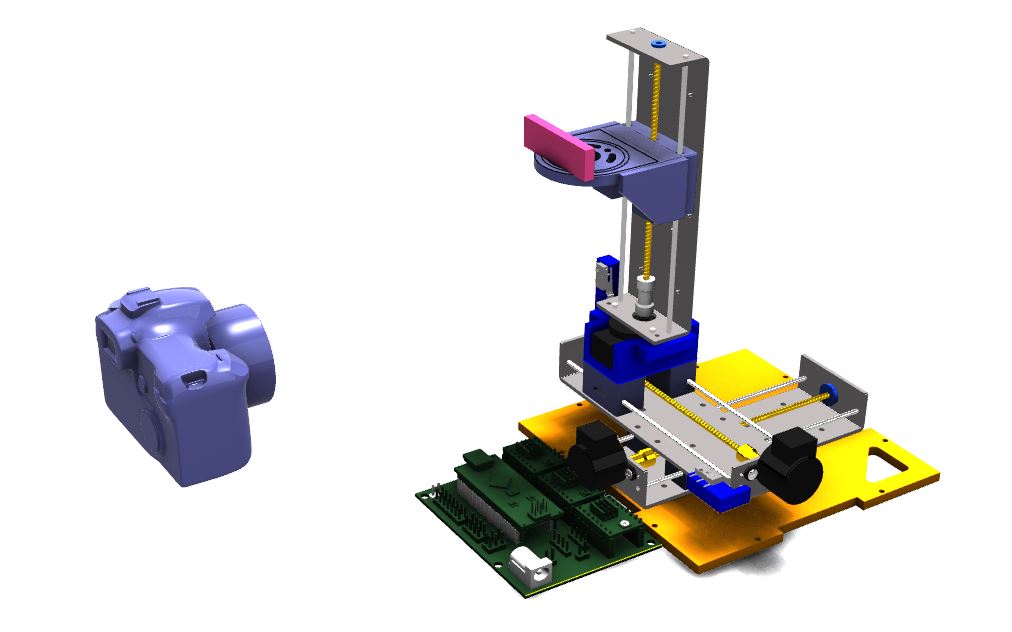
I also added a camera model for further explaining. I took it from here
And this is the result!
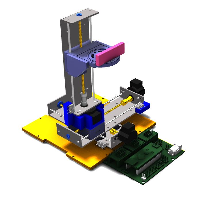
Tada!
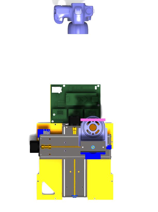
view with the camera
I added also an idea drawn by hand of how it’s the wiring so I can work on it later.
wiring is important
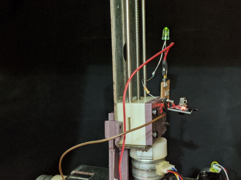
Mounting the Light machine
Once we have access to the lab it’s time to get hands on and start 3D-printing the files to make the endstops.
Also I added a pieces to connect the circuit that it’s going to handle the led.
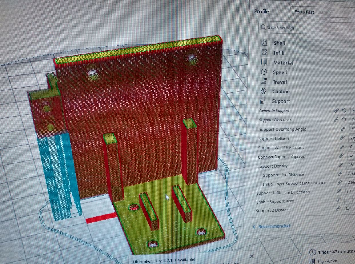
I like the blur when I take those photos of the Cura4 of the lab.
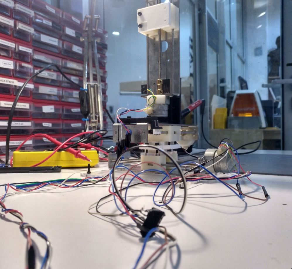
And this is how it’s get mounted
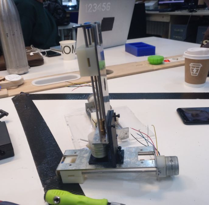
Y and Z
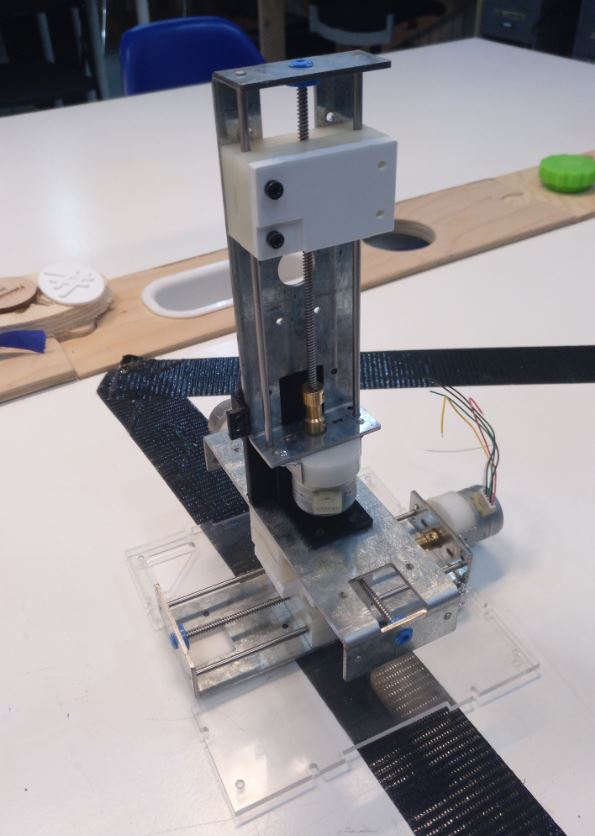
X (with the bottom of the SPML) Y and Z
This was a hell to mount. The holes are too small so the screws had to be screwed twice to fill in and the distance I measured in the model between the centers of the circles was 39 mm and in reality it was 40 mm.
So this was very bouncy.
Also the X-Y connection was very difficult to screw because it has very little space to manouver.
So I did it again later correcting the pieces. And when I changed them it was much sturdier so yay!
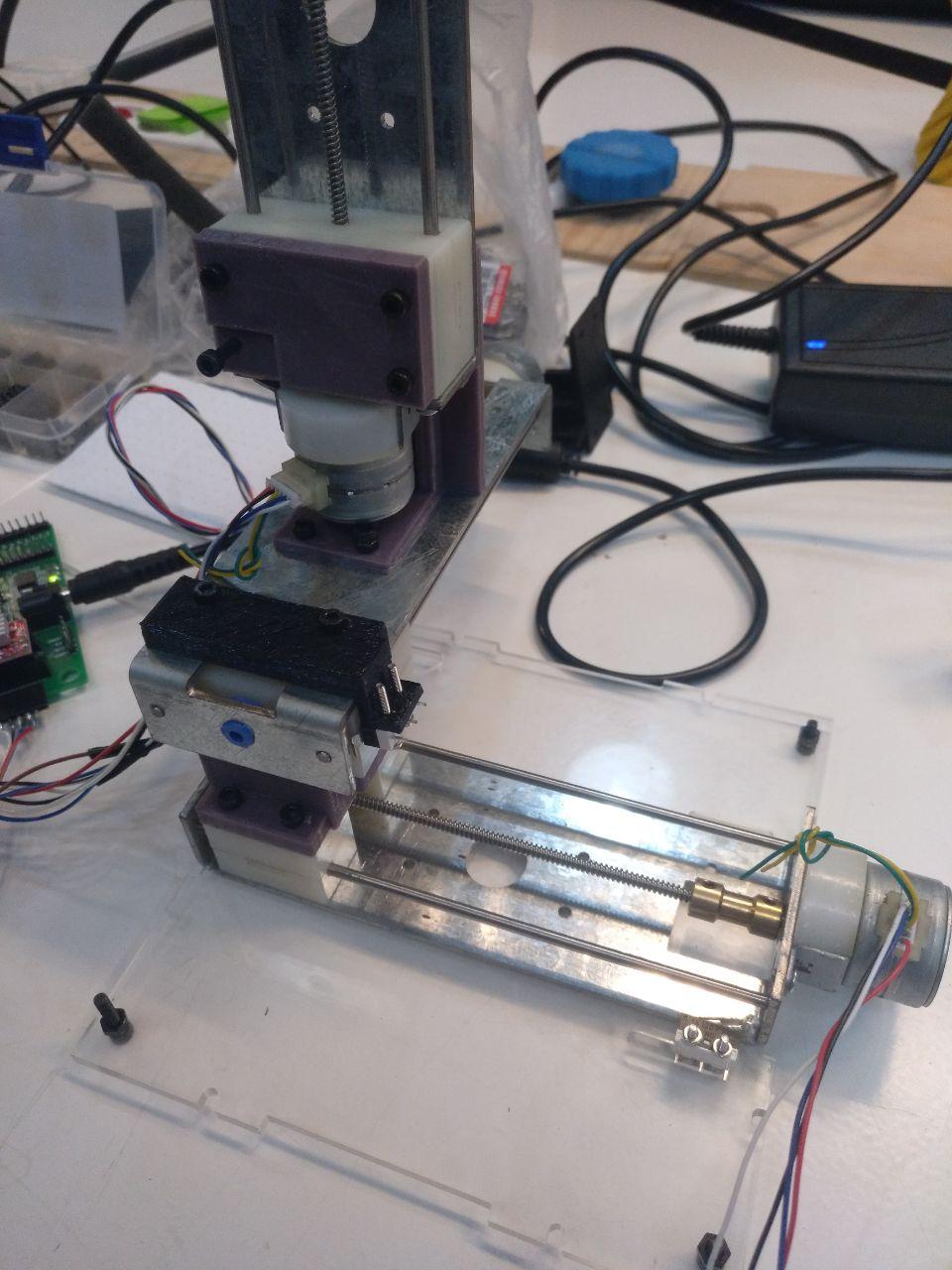
The connections
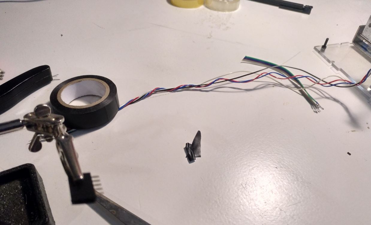
Ok, so these are unipolar motors. And we have bipolar drivers. So we have 6 cables in the steppers and 4 cables in the drivers…
loading drama…
So the solution is that these motors have these connections of the schema
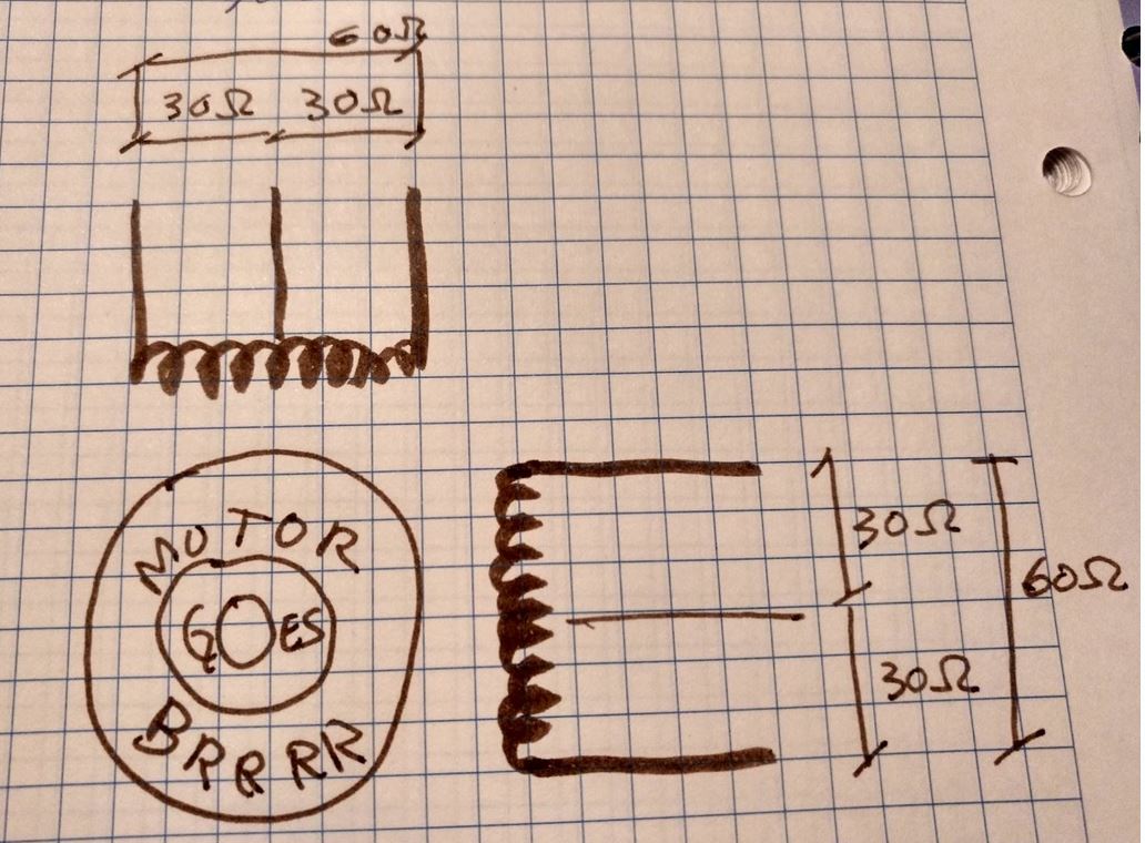
the rotor goes brrr
So the six cables are 3 for one of the electro magnets and 3 for the other one being 2 at the extreme opposite of it and one just in the middle. So you can measure the resistance of the cable beteween them as shown.
The cables that you have to connect are only those that are separated by 60 ohms by couples.
A1 - A2 - B1 - B2
And if you want to invert how the motor goes, you just have to twist the cable and connect it upside down (B2B1A2A1)
And then you can make connections and connectors
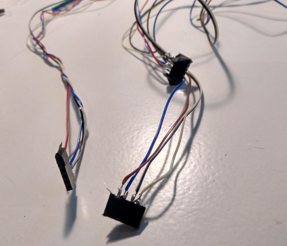
I specially like this photo
Now we have to make it move properly.
Instructions to bake the GRBL and make it work
Now imagine that you have your CNC shield and your barduino.
Now how to make the firmware work?
After days of wondering and pounding against some several walls, I found how to make the software work. More or less (more less than more) but I can save a headache of someone in the future. Here are the
So you first go to the firmware details of the SPML project and download it (or all the repo) if you didn’t.
When you open in arduino IDE it’s this big:
many files are many
How do you deal with those kind of big projects?
You don’t. At first at least.
Now if you try to compile you won’t be able to.
If you have arduino IDE, you should first install the libraries that you might miss. You can look for them in the library administrator of Arduino IDE or you can download them fromt the repo here. If you do there is an option to add a library as a folder (selecting inside the folders, not the folder containing both libraries)
Now if you try to compile you will have another error.
Then you should check in partition Scheme to “Minimal SPIFF”
Then you can upload to the chip.
But you have not ended yet. You should be able to connect to the barduino but… it will say that index.html.gz is missing. So you can download it from the repo. And then you can connect
Then you’re ready. More less.
When the instructors said that this was the easy path. I think of how difficult could be the hard way and tremble.
Problems. Lots of problems
We had lots of problems making the X and Y axxis move. Finally we had to substitute the stepper drivers
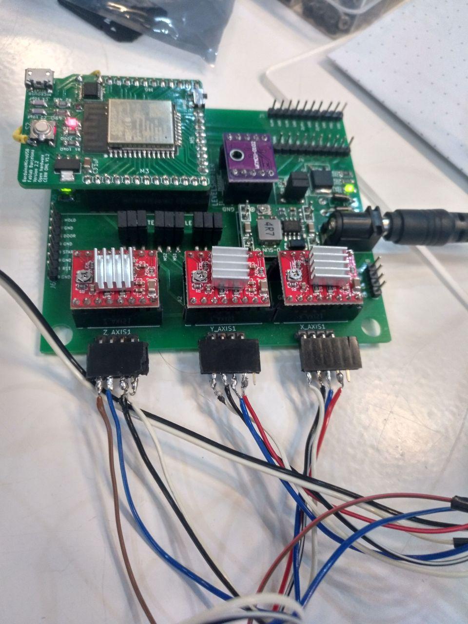
The substituted are with the dispipator in other position
We also had a problem with the circuit that Tue did because we designed to host an addressable LED and that’s quite different and harder than a normal LED. So we changed to a normal LED
Also we had problems finding which command we need to operate the LED
Finally we’re using the PWM3V3 of the spindle LED that is mapped in the spml.h in the machine directory of the firmware and mapped also in the cnc shield.
The command to turn on the led is M3 S4000 (turn on spindle at 4000 rpm, it doesn’t really mater much because it’s just a pwm signal) and to turn it off is M5.
With that information WE CAN DO STUFFF
Making the GCODE through CURA
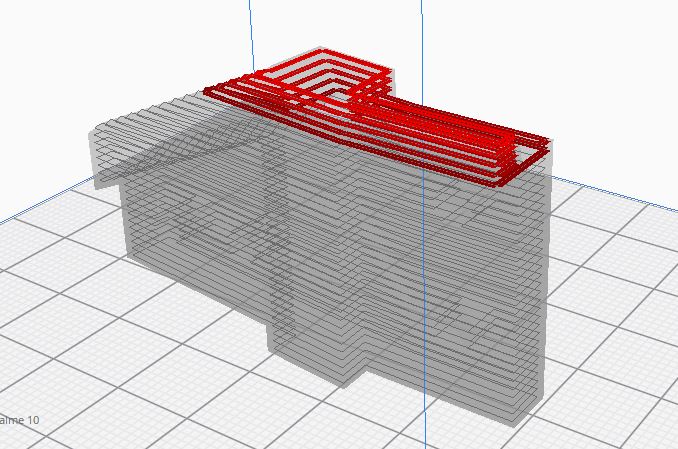
So now we have something that moves, but we need a model and that it moves accordingly.
First we used and stl that I have from the Monolith just to test it.
Making a specific fake 3d printer
So we have CURA the slicer. Since it’s a 3dprinter slicer it’s meant to do things that way. First we set up the machine (naming for example light machine)
I tried several flavors of gcode (marlin and another one that I don’t remember) and I didn’t see much difference because I’m cutting most of the part afterwards.
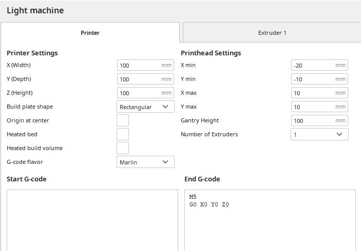
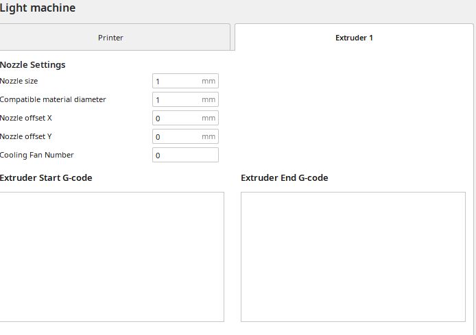
light machine configuration from “custom” with no delta type
Then the settings are going to be with lots of warnings because we’re setting things in another way.
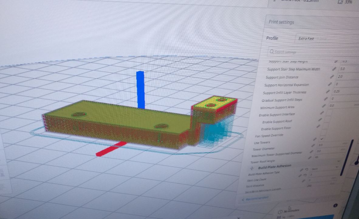
If you want, here are the settings of the Cura for the light machine with 3mm between layers
But it’s more like this image
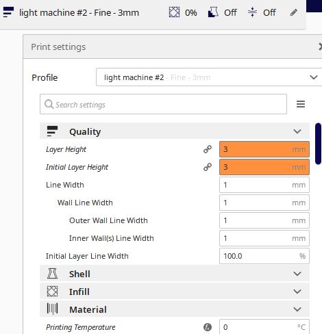
No infill, no adhesion, no top face, no bottom face. Then you press slice, check the preview and save to file.
Then you have to trim it with notepad or other text editor.
Trimming the GCode
Ok, so the thing is, if there is any command that the machine don’t understand all the file is not going to be processed.
So we have to cut lot’s of things. And add some. (Because we want to light the LED)
Also remember that lines with no code also have problems, so better to delet them.
First, the part on the start:
;START_OF_HEADER
;HEADER_VERSION:0.1
;FLAVOR:Griffin
;GENERATOR.NAME:Cura_SteamEngine
;GENERATOR.VERSION:4.7.1
;GENERATOR.BUILD_DATE:2020-09-02
;TARGET_MACHINE.NAME:Unknown
;EXTRUDER_TRAIN.0.INITIAL_TEMPERATURE:0
;EXTRUDER_TRAIN.0.MATERIAL.VOLUME_USED:4283
;EXTRUDER_TRAIN.0.MATERIAL.GUID:a4255da2-cb2a-4042-be49-4a83957a2f9a
;EXTRUDER_TRAIN.0.NOZZLE.DIAMETER:1
;EXTRUDER_TRAIN.0.NOZZLE.NAME:unknown
;BUILD_PLATE.TYPE:glass
;BUILD_PLATE.INITIAL_TEMPERATURE:60
;PRINT.TIME:180
;PRINT.GROUPS:1
;PRINT.SIZE.MIN.X:20.935
;PRINT.SIZE.MIN.Y:42.778
;PRINT.SIZE.MIN.Z:0.3
;PRINT.SIZE.MAX.X:79.015
;PRINT.SIZE.MAX.Y:56.889
;PRINT.SIZE.MAX.Z:33.3
;END_OF_HEADER
;Generated with Cura_SteamEngine 4.7.1
T0
M82 ;absolute extrusion mode

G92 E0
M109 S0
G280 S1
Go out
Search and delete these commands
M107
Replace
” E” for “; E” because we’re not using the extruder.
And for how we set the light on and off
We set an M3 S4000 (spindle on) before every G1 (this is operation)
We set an M5 (spindle off) befoer every G0 (this is travel)
With that you will have a more simple gcode. But with lot’s of M3 and M5.
If there is something wrong with the file, the GRBL page is going to say where the problem is so you can track it!
Setting the dark space
The first trial was in a little space in the lab where we can take photos.
hello darkness my old friend
I added some black cloths to make it darker because the LED was not very powerful and also because I prefer for these photos to have total darkness.
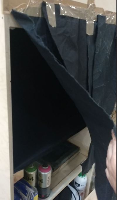
tape with cloths. Of course
I also put some cloth in the machine because the IR was connected and had an LED. And also I covered the CNC shield and the barduino gently to cover those leds
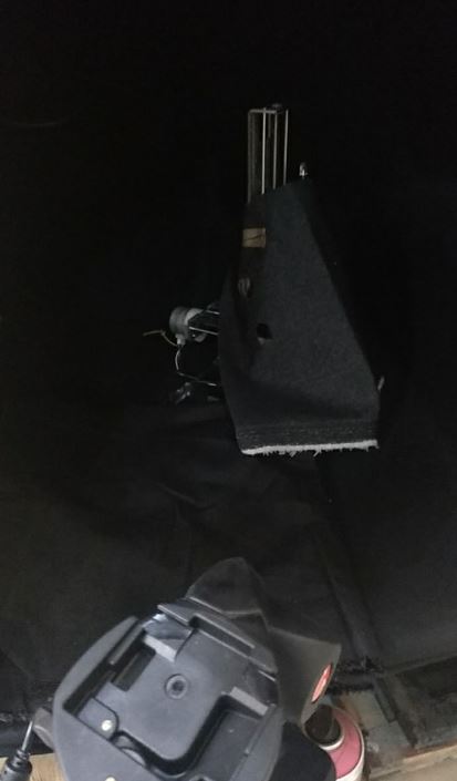
it’s like a cape
I used one of the 3d joints of the Monolith as a test.
you’re the first
And once I sent the test without the darkness I realized that it’s going to take loong so I modified the speed ranges to be faster.
And also my camera (a canon eos 450D) has two options for long exposure, or up to 30 seconds or as long as you’re presioning the button. So I had to speed up.
I did but not as much as doing all the model in 30 seconds.
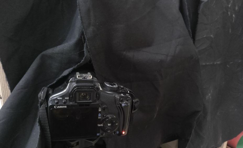
say cheeeeeeeeeeese
So I did instead of one take, I did several images and added them together in Photoshop in “brighter” mode layer.
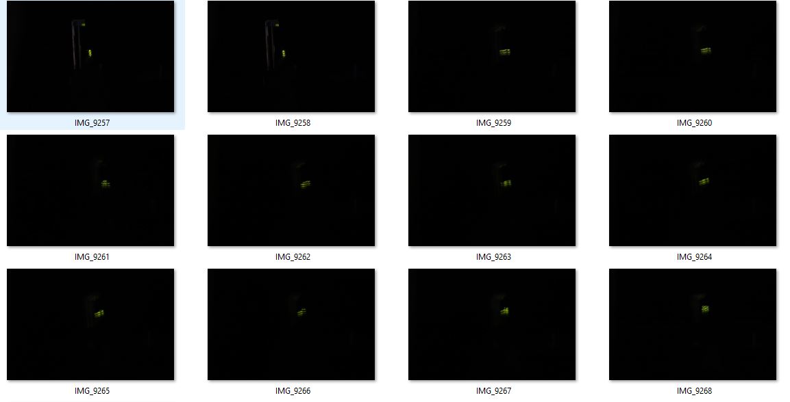
This is the result for the first test:
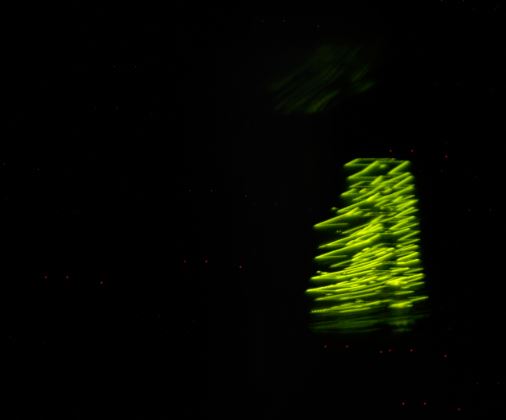
LIGHTS IN THE DARKNESS
Cool isn’t it? But I don’t dinstinguish much. So we went for another shape that could be more figurative.
Irish setter cookie light
I went to thingyverse to look for a stl file that I could slice and would be appropiate. I found this one
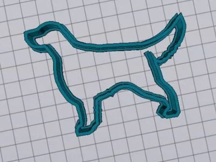
GOOD BOY
So I went to the cura, made the slice

And I realized that I had to swap the axxis of the machine. Because I’m taking the photo from more-less the front. And the 3printers always go from z low to z high I’m going to have an image quite uninteresting and I’m not going to see the dog.
So I swapped the Z and the Y axis.
Here are the connections and the setting
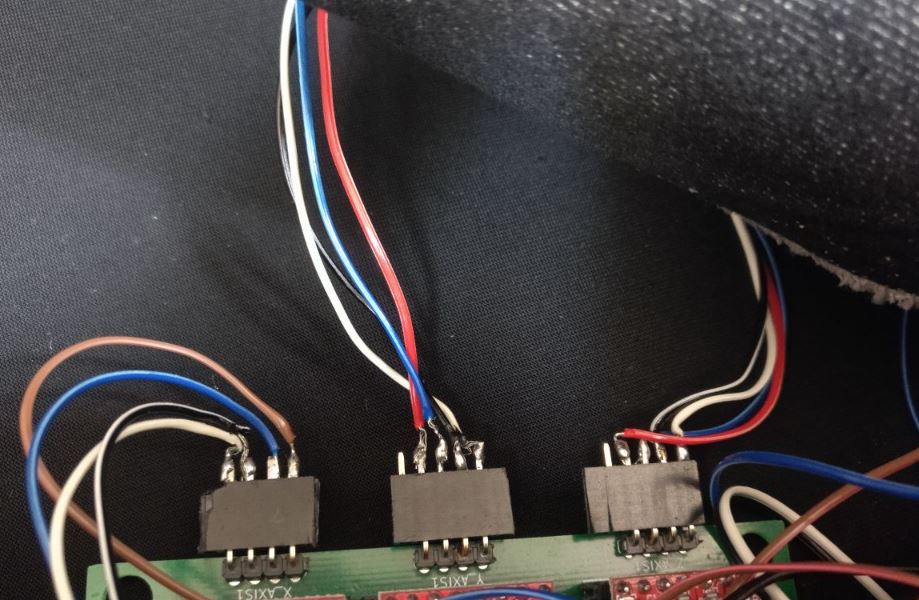
David and Tue of the future are going to thank how should be the cables
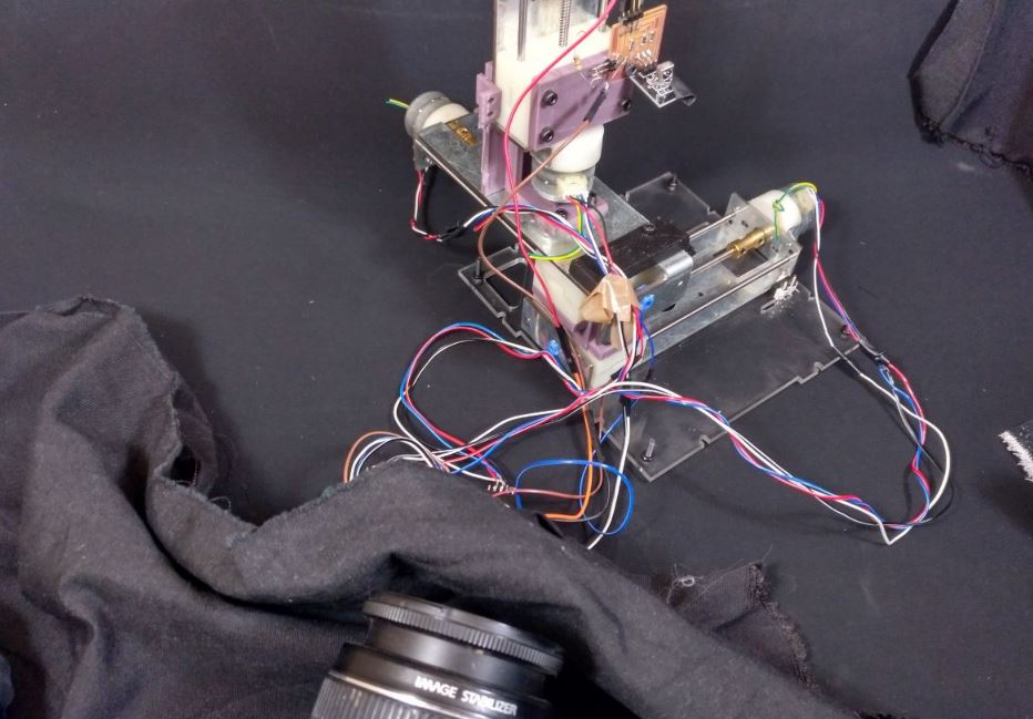
Almost ready to shoot
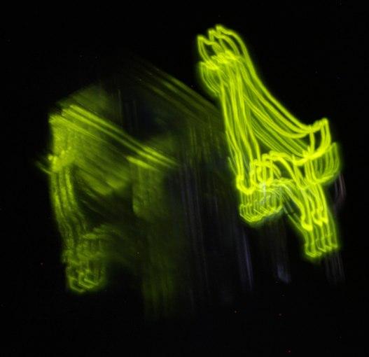
Doggy shoot!
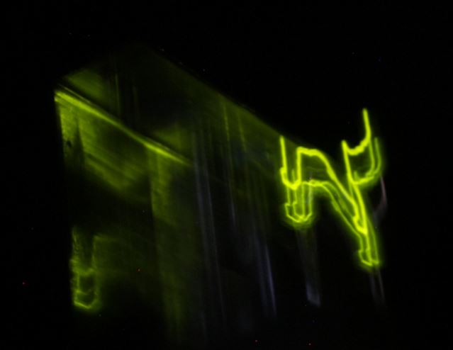
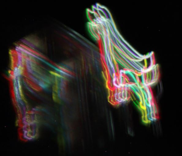
This is one of the shots. And if I put them all together…
I also tweaked with photoshop each photo to have one distinctive color and this is the multicolor result:
Links
The sloth camera slider. http://barcelonamachines.fabcloud.io/group4/
Design files
Remember to use download link as.. to download the files.
Settings of the Cura for the light machine with 3mm between layers
Fist Gcode sent (already trimmed) 3d piece from the Monolith