Final project - interface and tracking
Files and resources
Conceptual design
This last part of the project is about acquiring data:
- From the pressure source: an interface has been developed to communicate with it.
- From the soft robot: a 2D tracking system using image processing has been implemented to characterize the bending. Other data acquisition modules could of course be considered (force sensors, 3D tracking, …)
Interface
Developing the interface
Basically, I want to plot data, and to control outputs. A plus would be to integrate the image processing part in the same window, so I want my interface to be modular.
Since I fall in love with Python, and that I started the image processing using python, I will use this langage for my interface. As a reminder, I used my board as an Arduino. Here are the libraries that I used:
- Pyserial for the communication
- Tkinter for the interface
- Matplotlib for the data visualisation
- Numpy because you need Numpy
And the tutorials that I followed:
- Pyserial and Arduino
- matplotlib and real time plotting
- Good practice for Serial communication
- Neil’s example, for the structure of the code
After several developments, here is the first version of the working interface:
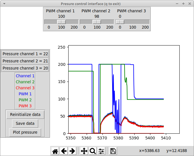
Note that a complete documentation of this first version of the code cna be found in week 16 documentation. Ok, I agree, it is not very fancy, but it does the job! It plots and saves the data, and allows to communicate with the board! Note that neither the PWM values nor the pressure values are calibrated: they still mean nothing! More, the pneumatic circuit behind it is not fully connected, so the window showed here is just an example! However, you can see that the pressure reacts to the PWM, that can be adjusted with the sliders: good! I will detail a little bit further the key parts of the interface below. I also implemented 2 ways of saving the data: saving them as Numpy lists as the action of a button, and saving them automatically in a csv file, at each idle loop.
Final version of the interface
For the final version of the interface, some cleaning was done:
- The pressure and time flag is aquired for each channel and can be plotted.
- When the save button is pressed, the data are saved in csv files.
- The communication is now only in one direction (from the board to the interface). The pressure can also be controlled using the potentiometers. It is of course possible to restore the two-directional communication, but would require a little bit of work.
The final code can be downloaded at the top of the page.
Further improvements
Two axis must be considered here for further improvements: the communication between the board and the interface could be improved to develop the possibility of a real control of the pressure. The data acquisition modules (bending/forces and pressure) should be integrated, especially to synchronize the data.
Tracking
principle and 2D tracking
I want to be able to know the position in my soft robot in the 3D space. The idea is to be able to extract the curvature radius from a video of the soft robot, and from this, potentially reconstruct its shape and position. For this, I make the following big approximation: the soft robot can be considered as a line.
Here is a schematic of the implemented workflow:
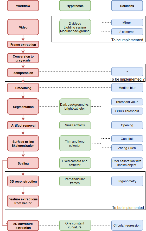
The implementation of the workflow is fully documented in week 6. I used the open source library OpenCV. The two main sources were the following:
As shown on the diagram, not all the process has been implemented. However, as shown on the image below, the skeleton extraction has already been done! I implemented 2 solutions for the segmentation: using Otsu’s threshold or using a threshold based on a gray value. Even is the first one is more adaptive, it is an iterative algorithm, and consequently increase strongly the computational time. The big hypothesis here it that the catheter is considered as a line in the 3D space, so this skeleton extraction makes sense. Once all to coordinates of the skeleton have been extracted, I basically have a vector, and can imagine to compute almost any information from it, as documented in week 6 (curvature of each point, position in 3D space, …). However, for the moment, and for the demonstration, I only worked on a 2D video. From the skeleton, I extracted the best fitting circle, which is a way to compute the radius of curvature of the catheter:
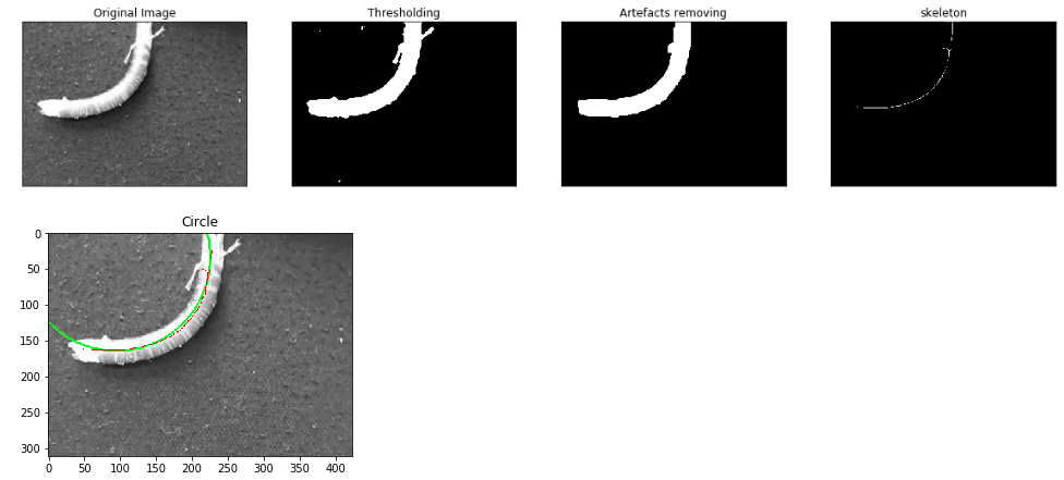
Concerning the scaling, I made a small algorithm allowing to compute the scale factor in mm²/pixel, by taking a picture (without moving the camera) of a rectangle of known size. All the codes can be found in the top of the page!
An example on a video token with the final setup:
Further work
- The synchronization of the frames with other data (typically the pressure) is not yet considered.
- Several parts of the workflow must sill be implemented.
- The computational time is for the moment a limitation. Two steps are limiting: the skeleton extraction, and to a lesser extend the smoothing/segmentation. Since it is difficult to modify those algorithms, two solutions can be considered: even trying other algorithms, even compressing the images at the beginning of the workflow (by reducing its size and/or quality). This will need to be tested, to ensure that no information is lost.
- An alternative to characterize the motion of the soft robot is to use marker (for example colour dots), simpler to track in the 2D or 3D space, since the markers have only one dimension
- The development of other acquisition methods (typically force sensors) will also be part of further developments.