Computer-controlled machining
Objectives of the week
- Group assignment
- Test runout, alignment, speeds, feeds, and toolpaths for your machine
- Individual assignment
- Make something big
Again a week of unknown for me! I never used any CNC milling machine, I am looking forward to!
What I did
- Tested several CAD software
- Planned and launched a CNC for the first time...
- ... and made a chair
What I learned
- How a CNC machine works and how to use it
If I had the time to go further...
- I would have made a lot more chairs!
Files and resources
- The stl files of the first version of my chair can be downloaded here
- The stl files of the improved version of my chair can be downloaded here
Step 1: Group assignment
Equipment
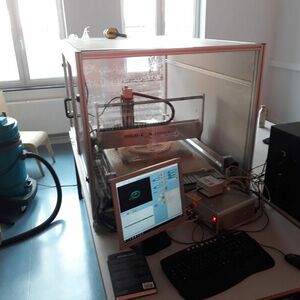
We worked this week on different machines. Amy used the CNC from a friend that owns one at home. It also gave her more time to mill out what she wanted to mill out and the co-students in the ULB lab more time for their assignment. The machine in the lab is a High-z 1000T, controlled using kinetic-NC.
Mills
Amy used a 4mm flat endmill. She soon figured out that milling a straight line of 40mm did not result in milling 4mm out. Originally it would be 4.60mm, by changing some settings we got to 4.15mm.
At the fab Lab, we used a 6mm flat end mill.
Christophe made some press-fit tests, and it resulted that the alignment was perfect without adding any correction!
Rounded or square corners?
Concerning the corners, several things must be taken into consideration.
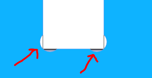
A new thing that We learned was to add little squares in the design. As the mill is round, we wouldn’t have straight corners. Amy added little squares in the design files of 4.5 mm on 2.5 mm so that my corners would be square.
Fir the press-fit, we would have the same problem. For example, if we have 2 squares fitting, the inner can be perfectly squared (since the mill goes externally), but the outer square can’t (a fillet of the same radius than the mill will appear). We have here 2 solutions:
- As Christophe did above, replace the corners of both pieces by fillets of the same radius, larger than the mill radius.
- Add dogbones, little holes of the same diameter as the mill in the corners, having their circumference coincident with the corner.
Speed/feed rate
Standard this was on 3000, but we changed it to a 1000. While milling out, we could also still change the rate if we thought it could go faster or slower. Makezine has a interesting article about this. And the Carbide 3D (the second CNC milling machine that Amy use) has a library for the rates. This makes it easy to start milling without having to do to much setup. We made tests with the fablab’s CNC, varying the federate between 800 and 1200 mm/min using the kinetic-NC interface:
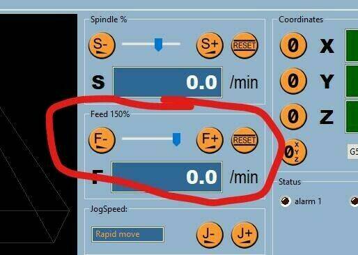
If the feedrate is to high, you can hear it, and the mill will suffers. 1000 mm/min showed to be the best feedrate!
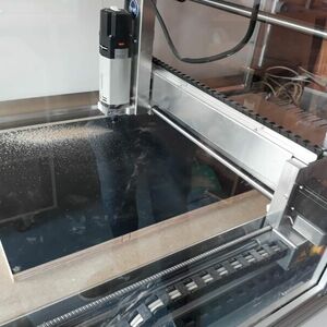
Milling air
As every careful machine operator the first time we started the machine we milled air. We even managed to get some mistakes out of the files because of that. But of course that’s not all. So before we started milling out the big plates, we took the file of the small shelve and milled this one out. It actually went perfect from the first time on.
Safety!
As was stated during the course, making a mistake on the CNC can have serious consequences for the machine, the room but also the people close to it. The machines on which Amy will mill don’t have a protective case. The Shapoko has a plexi plate that keeps most of the flying debris away from people (we corner the machine so that it’s ‘safe’. The BZT doesn’t have any case either, but we’re sitting far enough from it to be safe. The fablab’s CNC has a safety opening on one side: if the doors are open, everything stops!
As we stayed with the machine during milling, I was using protection (on ear and in ear) and also a dust mask.
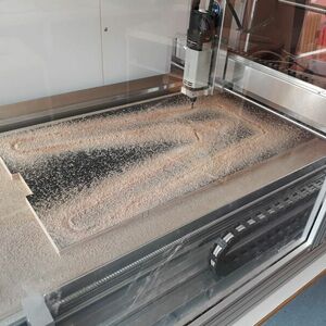
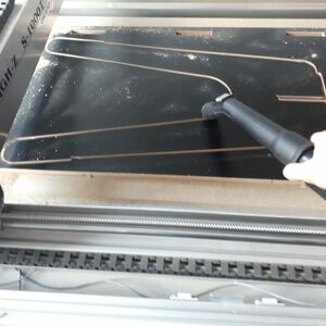
Dust collection
None of the machines that we worked on this week has a proper dust collection. Not having a dust collection on the machine resulted in getting up every once and a while to check on the machine and vacuum the dust away. Always being careful to be opposite to the mill so that we wouldn’t come into contact.
Step 2: designing my “something big”
Searching for a good idea
My first idea was to do something for my project. I finally decided to do something else for two reasons: it was not big enough, and the CNC in not the most adapted tool for it. However, I made the CAD design of my pieces for the final project this week, all the documentation can be found in the project’s development page.
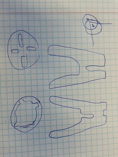
My second idea was to make something for the Fab Lab. Since Christophe will work on a bar for the kitchen, I decided to make the associated chairs! I made a first draft on paper: I want to make a press-fit chair in four pieces. I also discussed a little bit the idea with Victor, the design expert of the fab lab.
CAD design of my chair
First try on Fusion 360
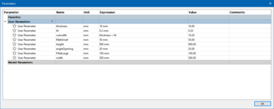
For this week’s project, I decided to try to use Fusion 360. I could download and install a student version. This was the first time that I used it, and it felt really easy at the beginning! It is very intuitive, it has a nice interface, and it is really easy to use parameters!
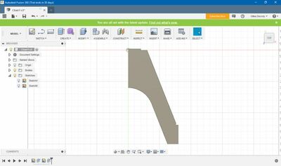
But when it comes to version and files management… It becomes very complicated! Even with the help of Adrien and Victor, I found it very unpractical. Seeing the need to move on on the week’s project, I decide to use Solidworks, a tool that I master.
Backup solution: using solidworks
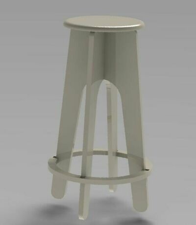
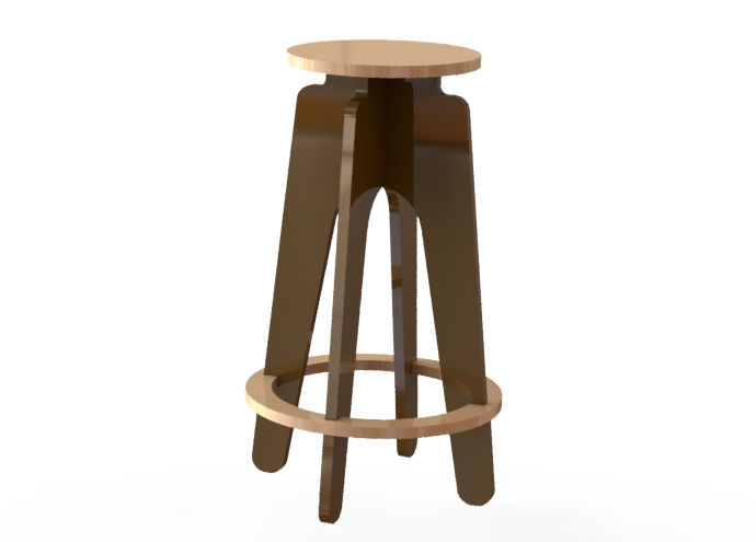
Now I find it very easy! I made a perfectly parametrical chair. After a few design consideration with Victor, our fab designer, here is the new version of the chair!
Step 3: milling my “something big”
Configuring the milling using HSMWorks
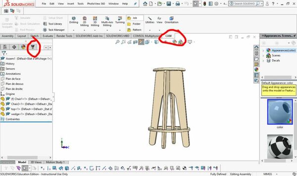
For this part, Christophe, our CNC milling expert, gave me a lot of help! He guided me through the configuration explaining me the why and the how of everything. Good tutorial can also be found on this page. Once the CAD file is finished, the milling must be configured. For this, I use HMSWorks, a Solidworks plug-in developed by Autodesk. New menus appear in the Solidworks interface:
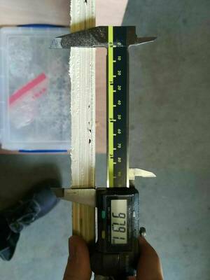
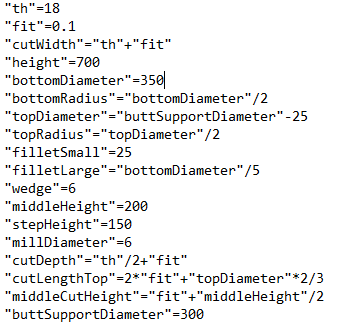
I will use 18 mm plywood and a 6 mm milling tool. Problem spoiler: I made all my configuration with 8 mm diameter mill, so all my pieces were 1 mm larger than expected…
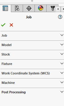
To configure the milling, you have to create a new job in the cm manager: CAM manager (left panel) -> Right click -> new job You can then edit your job. Here are the parameters to setup:
- Job: type of job (here milling)
- Model: pieces to mill
- Stock: define the stock dimensions (here: relative size box with a side offset of 10 mm)
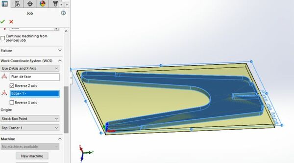
- WCS: define coordinate system used for the job. This is important to set correctly! The x indicates the longer axis of the milling machine, and the z must be directed upwards. The origin is also important and will be set by calibration before each milling on the machine. Using the corner of the stock is here used.
- machine: define the machine (here default)
- post processing: (here default)
Once the job is created, you can add milling steps. We will here mainly use 2D contours: top menu -> 2D contour. You have now a new set of parameters to setup.
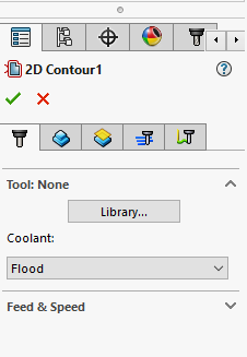
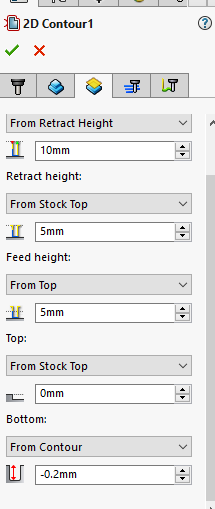
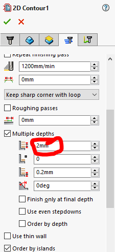
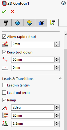
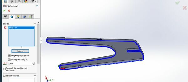
Important parameters are the tool, that you must create. For the contour to cut, it is better to select a contour on the bottom face. Be sure that the arrow that indicates the cut is placed on the correct side of the contour! It is also good to add a bottom offset of 0.2 mm below to bottom, to ensure the cut. ANother important parameter is the depth of cut per size. I use here 2 mm. Finally, a ramp is used for the lead in.
Creating a new tool is quite straightforward bit requires to know many parameters. This page gives the values of those parameters for a given mill and material. Here are the parameters that I used (excepted for the diameter, which was wrongly set to 8 mm):
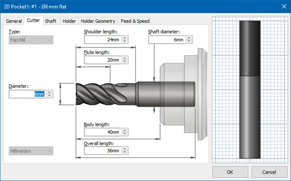
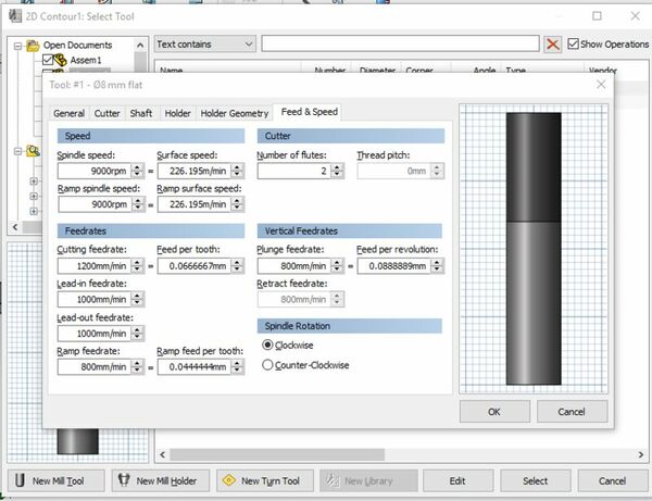
An important parameter is the feedrate, here set to 1000 mm/min as the other speeds after a few tests.
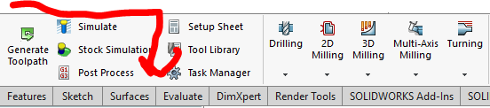
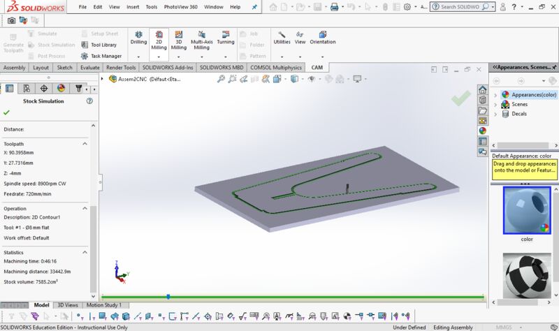
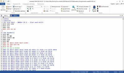
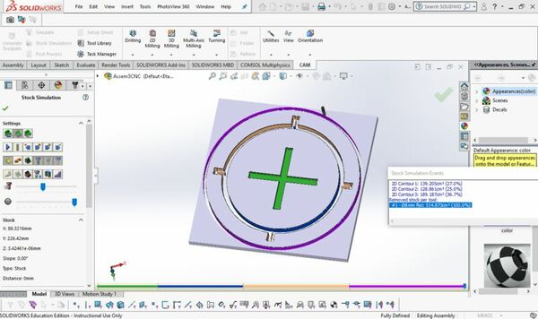
Once all the parameters are set, the gcode can be generated and the job can be simulated. The red arrow indicates the workflow to follow:
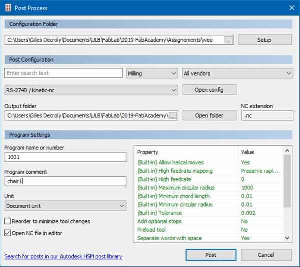
You can finally export the gcode using the post-process” button. A requirement for this is to download the configuration file of the software used to control the CNC, here KinetiC-CN. You must then use it to do the post processing.
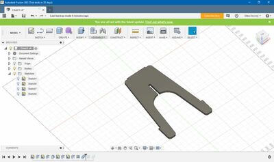
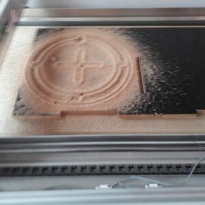
For the seat and the wedge of my chair, I do both in one cut. I must this time create several sub-jobs in the job manager. For the central cross, which is not through all, I use this time the pocket function instead of contour. This will also remove the central material. setting up a pocket, it is very important to uncheck the stock to leave box! Here is my configuration, using one pocket and 3 contours:
Note that this CAM manager offers no opportunity to add tabs to maintain pieces in place once cut. This is an advantage of Fusion on Solidworks!
Configuring the machine using KinetiC-NC
With the gcode (and still the help of Christophe), let’s use KinetiC-CN to launch the job.
- Open the file
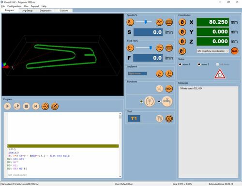
- Put the machine to park position (his “known home”).
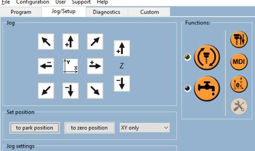
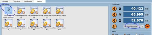
- Calibrate the thickness of the layer using the probe. Be sure to be in the G54 axis (axis of the milled piece)
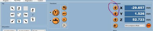
- Calibrate the x and y position of the origin of the job. To do this, use the software to place the mill above the desired origin and use the indicated buttons.
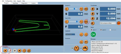
- Launch the job!
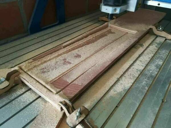
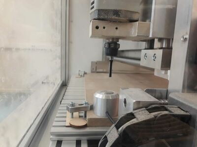
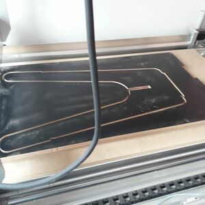
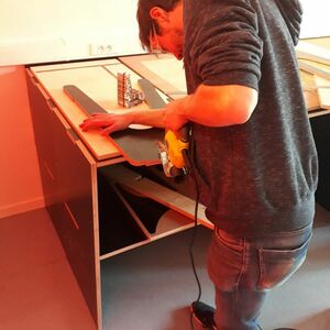
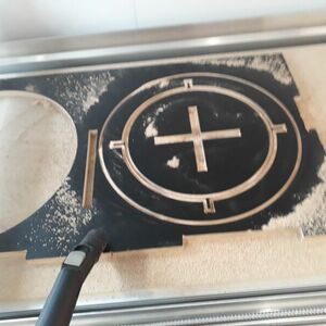
Milling and assembling the chair
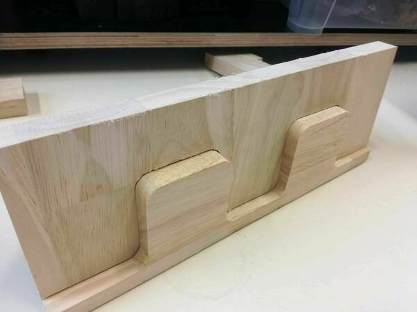
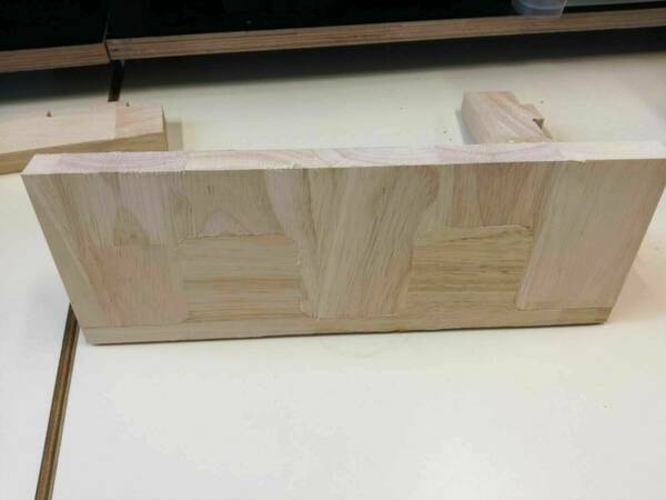
Here is a little roman photo of the milling. I encountered on problem: I used the wrong mill diameter in my setup (8 mm instead of 6 mm), so al pieces were 1 mm too thick.. It was possible to arrange some of the press fit (between the two vertical parts) thanks to Christophe, again, but I had to re-mill the seat and the wedge. A little bit of glu is also needed for the seat.
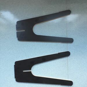
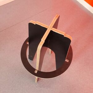
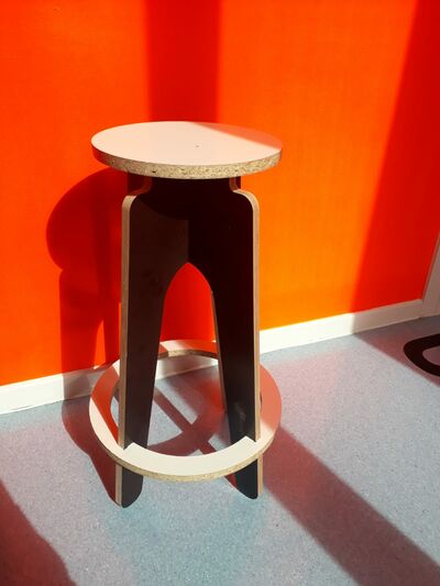
And here is the final result:
Step 4: improving my design
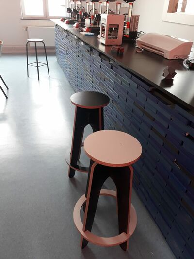
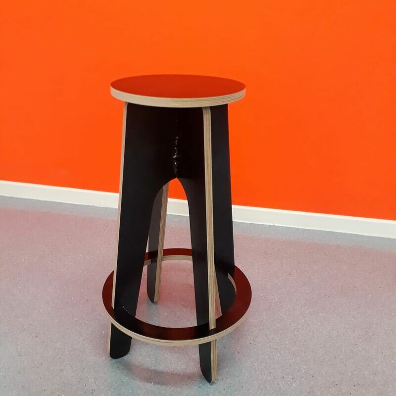
After several discussions with Victor, the designer, I made a new version of the chair, lighter and fancier.
And here is the milled chair!