Input devices
Objectives of the week
- Individual assignment
- Measure something: add a sensor to a microcontroller board that you have designed and read it
- Group assignment
- Probe an input device's analog levels and digital signals
This week will be the perfect occasion to start one of the main parts of my final project: the pressure control system!
What I did
- My satshakit prototyping board
- Used a pressure sensor, a potentiometer, and a switch as inputs
What I learned
- To program further an AVR microcontroller, and it was fun!
If I had the time to go further...
- I would have (already) finished my final project...
Files and resources
Step 1: Choosing my input (and output)
My idea is to use this week and the following to work on the pressure control board of my final project.
Principle
My pressure control board will be mainly inspired by the soft robotics toolkit, on which two solutions are documented:
The aim of my project is to have something similar to the complete board, but taking also inspiration from the low-cost version. Here is the block diagram of the board:
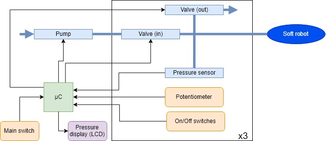
The blue parts are related to the pressure, and the yellow ones to the interface. The microcontroller would be connected to a computer to control the board using a user interface. The pressure value display is optional here (it would allow standalone operation, i.e. without connection to a computer). Additionally to those components, a power management system and controllers for the pump and valves will be required.
Bill of materials
Here is a first bill of materials, inspired from the soft robotics toolkit. The pressure must be controlled between 0 and 2 bar. The bold components indicate the components for this week.
| Component | Number | Supplier | Pressure range (bar) | Accuracy | Input voltage (V) | Unit cost (e) | Total cost (e) |
|---|---|---|---|---|---|---|---|
| Gauge pressure sensor | 3 | RS component | 0 - 10 | +/- 0.15 % | 1.5 - 12 | 10.12 | 30.36 |
| Potentiometer | 3 | RS component | 1 | 3 | |||
| Switches | 4 | RS component | 1.75 | 7 | |||
| Diaphragm pneumatic pump | 1 | digikey | 0 - 2 | 12 | 13.08 | 13.08 | |
| Solenoid valves | 4 | RS component ? | 0 - 10 | 24 | 27.24 | 108.96 | |
| Microcontroller | 1 | Microchip | 1.8 - 5.5 | 1.87 | 1.87 | ||
| breadboard | 1 | Rs component | 1.8 - 5.5 | 9.22 | 9.22 |
The choice of the solenoid valves is not definitive yet: they are expensive and I do not need to go up to 10 bar (but I need to go as low as 0 bar). The breadboard will be used for prototyping. More components will of course be required, including:
- A power management unit (to provide 5, 12, and 24 V)
- A control unit for the valves and pump. Two solutions can be considered here: a custom MOSFETs-based solution or using a commercial motor controller.
- Diode for protection if using MOSFETs
- Electrical jumpers, connectors and wires
- Pneumatic connectors and tubing
For this week, the aim is to develop a board for the ATmega328P, and to test one or more of the sensor parts (pressure sensor, switch, potentiometer) of the pressure control board.
Update week 13: the final bills of materials can be found on the Final project pages
Step 2: Making my prototyping board
I want to be able to make multiple prototypes of the control board. As Denis did, I will follow the Stashakit tutorial, to make my own modular board.
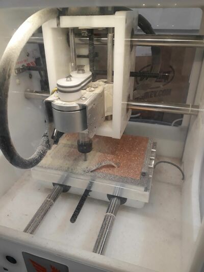
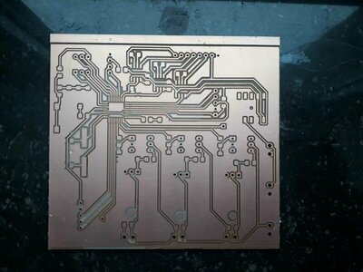
Milling the board
I milled the board using the same tools than in week 5. I tried first using the svg file provided on the Stashakit tutorial, but had a scale problem!
The working solution was to open and import the eagle brd file in KiCAD, and then export it in gerber format. I followed more precisely the same process as in this tutorial.
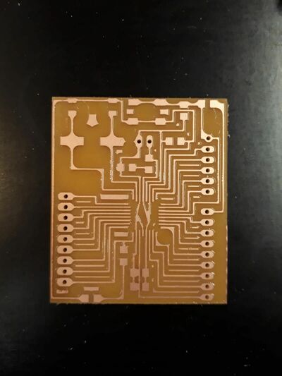
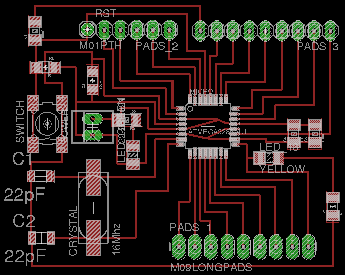
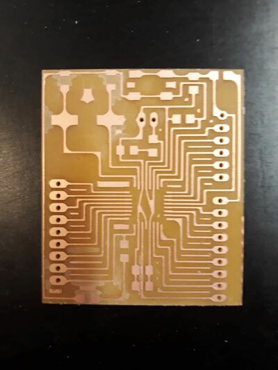
It worked! Only one little part was not milled, so I remove d a little bit of copper with a cutter, then double check with a multimeter. Here is the final milled board:
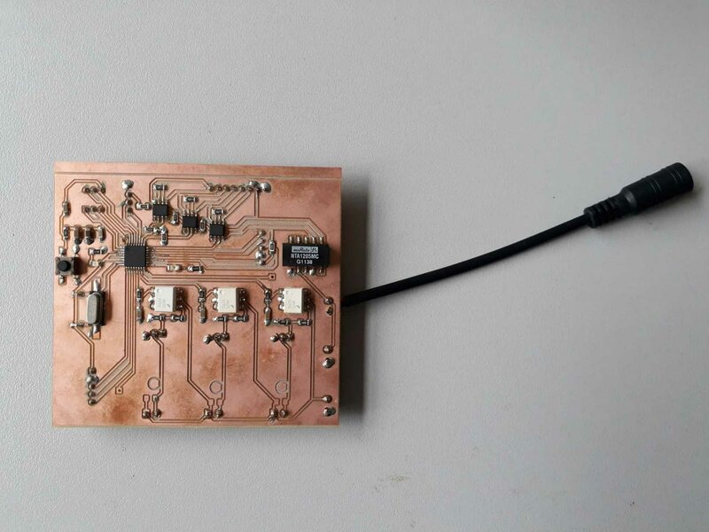
Welding the board
Here is the material needed for the board:
- ATmega328P-AU
- 1 Switch button
- 27 Pin headers
- 1 16 MHz oscillator
- 1 red LED
- 1 green LED
- 2 22 pF capacitor
- 2 100 nF capacitor
- 1 1 uF capacitor
- 1 10 uF capacitor
- 2 499 ohm LED protection resistor
- 1 10 kohm resistor
I used the same setup as usual, with the kind help of Geoffrey. We tested to use a technique based on flux, but it was not very convincing. Maybe we had a too thin welding head? We also moved the plastic part of the head, to have them well fixed and to avoid short circuits.
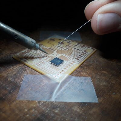
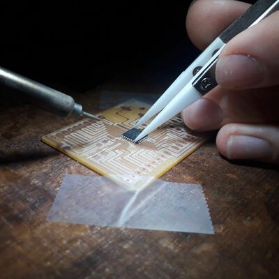
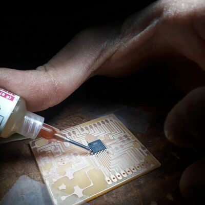
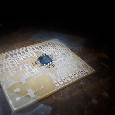

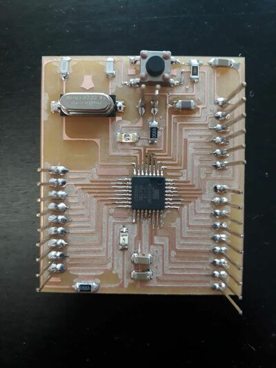
And here is the final board:
Testing the board
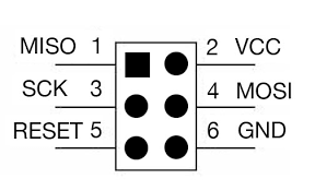
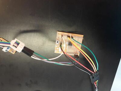
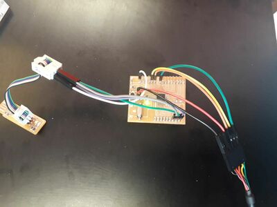
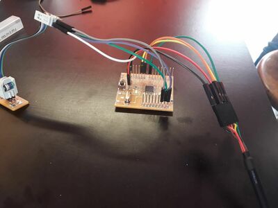
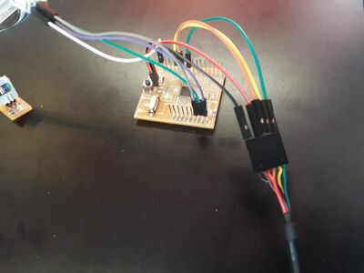
Next step: test the board! I used the same setup than in week 9: the FabISP is used to program the board, and the board is powered and can communicate with the linux machine using the FTDI cable. Be careful on the pinout! The pinout of the board can be found in the datasheet.
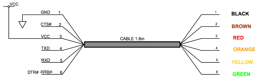
Here are some pictures of the connections from different angles:
To test the board, I adapted the echo program used to test the FabISP programmer and the hello board. I also adapted the makefile based on what I did in week 9. I had to be careful on several points:
- In the makefile: change the frequency to 16 MHz
- In the makefile: change the microcontroller to ATmega328P
- Set the low fuses to 0xDE. I used this online program to be sure of which value to use.
- In the test program: change the pin fr the UART communication (I also checked in the datasheet).
And, at the first try: it worked!
Trying to use an old laptop…
I had a Sony SVF152C29M with Windows 10 which was unusable and full of crap, and on which I decided to install Ubuntu. Vive la Fab Academy!
Everything works perfectly and it is a fresh start for the laptop, excepted that I cannot program my board from it… I can code, I can generate the hex file, I can communicate with it using the UART connection, but the programming does not work… What is weirder is that I use exactly the same setup, hardware, makefiles, and c code that I used with the fab lab’s machine, and that worked perfectl!
Here is the error message I got (a little bit truncated):
$ sudo make -f test.c.make program-usbtiny
avr-objcopy -O ihex test.out test.c.hex;\
avr-size --mcu=atmega328p --format=avr test.out
AVR Memory Usage
----------------
Device: atmega328p

Program:     828 bytes (2.5% Full)
(.text + .data + .bootloader)

Data:         50 bytes (2.4% Full)
(.data + .bss + .noinit)


avrdude -p m328p -P usb -c usbtiny -U flash:w:test.c.hex

avrdude: AVR device initialized and ready to accept instructions

Reading | ################################################## | 100% 0.01s

avrdude: Device signature = 0x1e950f (probably m328p)
avrdude: NOTE: "flash" memory has been specified, an erase cycle will be performed
         To disable this feature, specify the -D option.
avrdude: erasing chip
avrdude: reading input file "test.c.hex"
avrdude: input file test.c.hex auto detected as Intel Hex
avrdude: writing flash (828 bytes):

Writing |                                                    | 0% 0.00s
avrdude: error: usbtiny_send: error sending control message: Protocol error (expected 128, got -71)
Writing | #######                                            | 14% 0.15s
avrdude: error: usbtiny_receive: error sending control message: Protocol error (expected 4, got -71)

....
....
....


avrdude: error: usbtiny_receive: error sending control message: No such device (expected 4, got -19)
Writing | ################################################## | 100% 1.40s

avrdude: 828 bytes of flash written
avrdude: verifying flash memory against test.c.hex:
avrdude: load data flash data from input file test.c.hex:
avrdude: input file test.c.hex auto detected as Intel Hex
avrdude: input file test.c.hex contains 828 bytes
avrdude: reading on-chip flash data:

Reading |                                                    | 0% 0.00s
avrdude: error: usbtiny_receive: error sending control message: No such device (expected 128, got -19)
Reading | #######                                            | 14% 0.00s
avrdude: error: usbtiny_receive: error sending control message: No such device (expected 4, got -19)
avr_read(): error reading address 0x0000
    read operation not supported for memory "flash"
avrdude: failed to read all of flash memory, rc=-2


avrdude: error: usbtiny_receive: error sending control message: No such device (expected 4, got -19)

avrdude: error: usbtiny_receive: error sending control message: No such device (expected 4, got -19)
avrdude: safemode: Sorry, reading back fuses was unreliable. I have given up and exited programming mode

avrdude: error: usbtiny_transmit: error sending control message: No such device

avrdude done.  Thank you.

test.c.make:30: recipe for target 'program-usbtiny' failed
make: * [program-usbtiny] Error 1
And sometimes, after a short moment, the USBtiny on not even found anymore with ‘lsusb’ (which is always normal at the beginning).
Checking With Nico, one of the fab instructor, we did not found a clear answer to the problem. If I have time, I will continue to try to find a solution!
Programming setup
In the meantime, I can still use the two other ways to program my board and that I documented in week 9. Here is the setup
- Programming
- Windows 10 laptop: using Atmel studio and Atmel-ICE programmer using ISP protocol (Note that I can also use the fab lab’s linux machine)
- Ubuntu machine: Using the Atmel-ICE programmer, it also works! Note that you just have to use the command
sudo make -f file.c.make program-ice. - Interfacing - Ubuntu machine: for interface and UART communication
Do not forget to connect the ground and Vcc together!
Step 3: Using the sensors
Pressure sensor
First, let’s take a look to the datasheet.
The sensor has 4 pins: 2 for the power supply and 2 for vout+/vout-. As a first test, I simply connect a multimeter to Vout+/Vout-. I can use a 5V input or a 12V input. The second solution is preferred since it increase the sensibility to approximately ~10 mV/bar. The ADC of the ATMega328P works on 10 bits, i.e.1024 levels. If Vcc = 5V (which is the case), each I can measure 5V/1024=5 mV. This is not enough to have a good measure of the pressure!.
A possible solution here is to change the ADC reference. Instead of using Vcc, it is possible to use 1.1V or an external reference, as explained in the datacheet. However, this will only increase the sensibility of a factor 5, so I’ll need the second solution: amplify the signal!
Using the multimeter, I can measure something when I vary the pressure (really small as expected) but I have an offset of almost 3V… Which is much more than the ~1V expected from the datasheet! I’ll really need an amplifying chain…
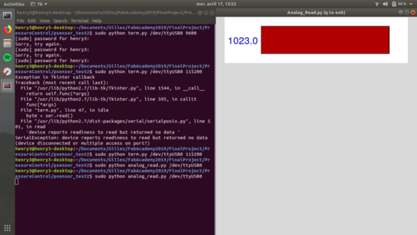
ADC test
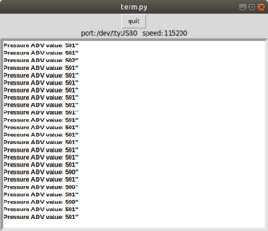
Let’s test the ADC of the board! I tested it based on Nico’s doc, who used Neil’s code and python interface. It gives respectively 0 and 1023 if connected to ground or VCC, which is correct! Else, it remain floating and the value varies slightly.
Note that all the codes are given at the top of the page!
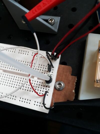
Getting a value from the sensor
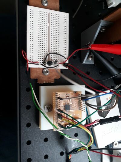
The, I connect the outputs of the pressure sensor using a breadboard: Vout- to ground and vout+ to the ADC, and I use a multimeter. Even if the variations are really small, the value given by both the multimeter and the ADC are coherent, good!
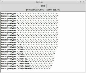
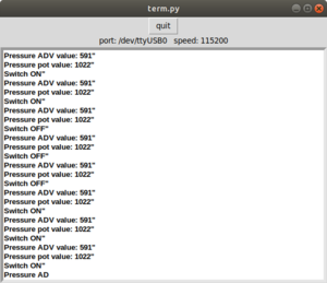
Displaying the value in the terminal
I want to display the values in the python terminal Neil gave us, to have more modularity. For this, I first transform the int value read by the ADC to a string to use the functions Neil Wrote.
Potentiometer
Let’s add the potentiometer (datasheet) to the board. Here is the principle schematic: the pin 2 moves, and the voltage measured on pin2 varies between the voltage of pin 1 and pin 2.
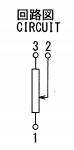
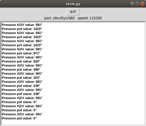
I connect pin 1 to ground, pin 3 to Vcc, and checked with the mulimeter: it works! To read the value with the microcontroller, I just have to add another ADC input and precise which pin I want to read in the loop.. And it works!
Here is my messy setup that I used to test it:
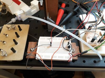
Switch
Same with the switch (datasheet). Here is the schematic:
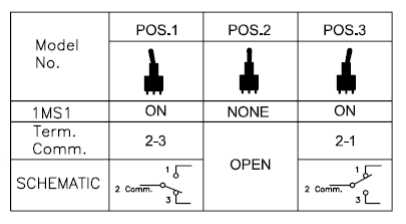
I connect pins 1 and 3 to the ground and Vcc, and pin 2 to my board. It works with the multimeter, and also with my board! Here is a nice tuto on how to use a button. Basically, you just need to set the digital port as input and read the value.
Step 4: further development
For my final project, here are the step that must still be done.
- Clean code
- Add more channels in parallel
- Make an amplifying chain for the pressure sensors
- Calibrate
- Make a or some nice PCB
- Use the data!
This work will of course continue in the context of the final project. This will be documented on the final project page on the pressure control.
Update week 14: making an input PCB
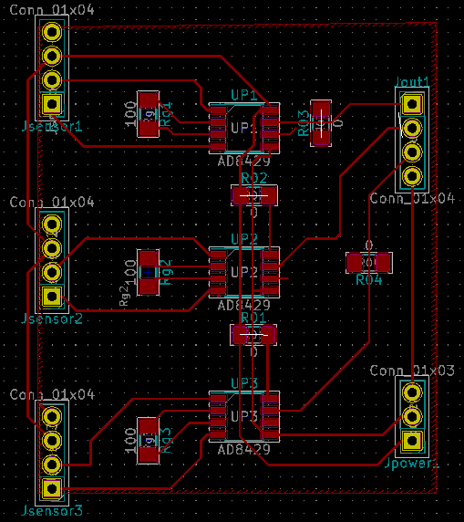
Since this week assignment was also about designing a making an input board, and to test further my final project, I made an input board (and an output board, this is documented on the final project’s page) counting for this assignment. This PCB is basically the amplifying circuit for the pressure sensors.
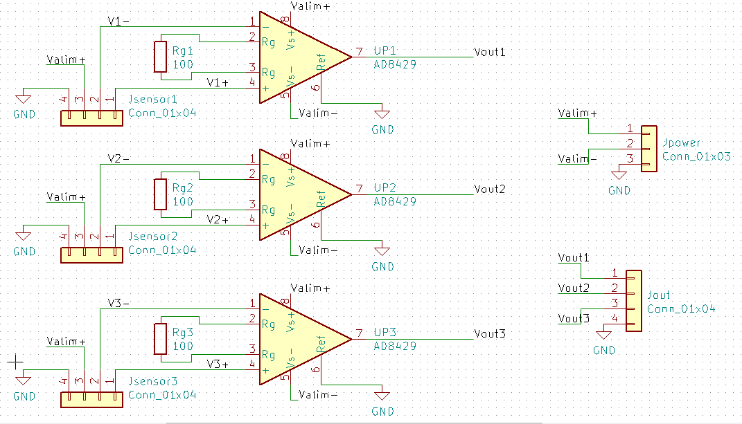
The alimentation voltage can be +/-12V or 5V. I chose only one voltage for both the pressure sensor and the op amp to make it more simple. 5V ensure the output to be limited, while 12V would increase the output signal of the sensors. The value of the resistors can be changed to adjust the gain! On the PCB, I added some 0 ohm resistors for the connections and a ground plane.
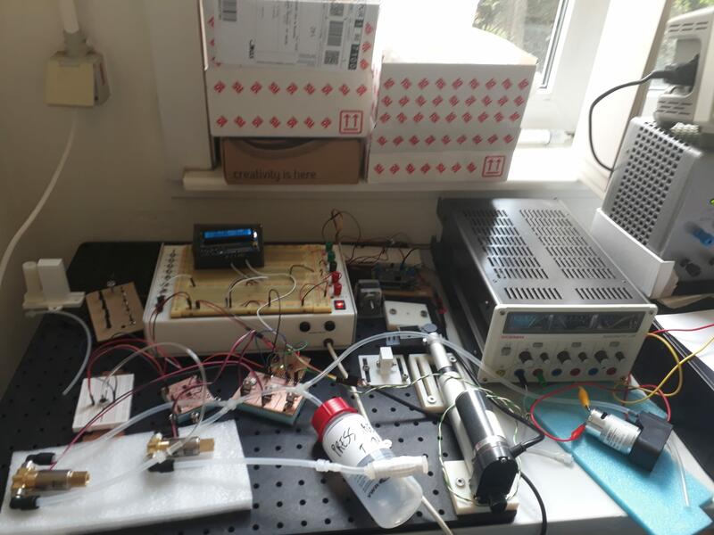
Here is basically how my all setup (with the satshakit, the input board, and the output board) looks… Just a little bit messy!
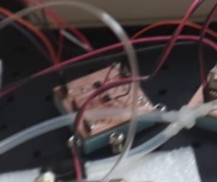
And zooming on the input board (you can recognize the differential amplifiers):
Note that I also made two other input boards, documented in the final project’s page: one to mount the potentiometers, and the other to mount the pressure sensors themselves.
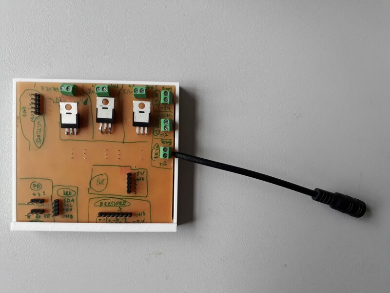
Update week 18: making my own board for the final project.
After some prototyping steps using my satshakit, I made my own board, including among other the outputs and inputs chains. This board is made of:
- The satshakit base (i.e. an ATMega328P with a 16Mhz crystal)
- The inputs (acquisition chain for pressure sensor, connections to the switches and potentiometers)
- The outputs (PWM driver, connections to the LCD)
- A power management system described below
- Interface and prgramming connections: (SPI and FTDI)
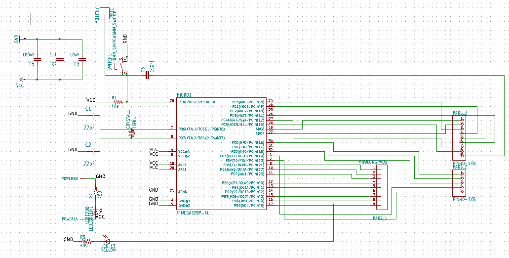
(you can click on the schematics and pcb layout images to show the pdf)
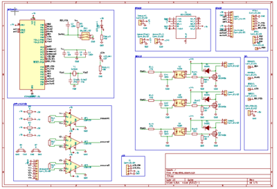
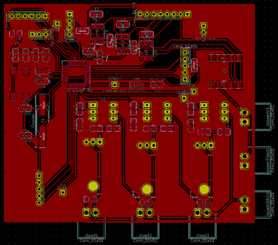
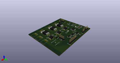
This is fully described in the final project’s page
Step 5: group assignment
To do…