3D scanning and printing
Objectives of the week
- Group assignment
- Test the design rules for your 3D printer(s)
- Individual assignment
- Design and 3D print an object (small, few cm3, limited by printer time) that could not be made subtractively
- 3D scan an object (and optionally print it)
This week is closer in my field of expertise. I already made a lot of 3D printed pieces with various printer for my research projects. However, I am completely novice in 3D scanning, and I this is a key feature I want for my final project, to be able to measure curvatures and workspaces.
What I did
- Tested 3D scan applications
- Had fun with a Prusa
- A first draft of my 3D reconstruction algorithm for my final project
What I learned
- How to characterize and calibrate a Prusa printer
- To use meshmixer
- That 3D scan apps are of low quality
- The principles of the formlabs printer
If I had the time to go further...
- I would test other scanners and printers
- I would improve my 3D reconstruction algorithm
Files and resources
- If you want to play with my head, download it here!
- Unfortunately I used the free version of the app for the 3D scanning, so I do not have access to the stl file. However, you can find the mandarin on sketchfab!
Step 1: group assignment
Tested 3D printers:
Torture test models:

Testing the Prusa i3 MK3
Print Settings
We made these 2 configurations with the printer

- 0.20 with Filament-PLA-silver (1.75mm, 200-220°C) with no support and no brim, infill 20%
- 0.15 with Filament-PLA-silver (1.75mm, 200-220°C) with no support and no brim, infill 20%
Results
 |
 |
|---|---|
| 0.15 mm | 0.2 mm |
For both settings the results are really good!
- There is no major defect
- The cantilevered parts are especially impressive
- There is no welding for close parts
- The vertical pins can be printed almost entirely

The difference between both parts is however very difficult to see. The main clue is in the inclined plane: It is smoother for low angle (~15°) for the second configuration, with the thinner layer thickness.
Testing the Up! Plus 2
Print settings

- 0.20 with Unic-PLA-Red (1.75mm, 180-210°C) with no support and no brim, infill 20%
Result

The results are also quite good!
- Even with the no support settings, the printed adds some support for the first Layer
- The geometry is quite smooth (really good on the inclined plane)
- The text renders with a lower quality, as the vertical pins.
- There is welding with the 0.2 mm clearance.
Testing the Form 2
Print settings

- Layer height was set to 0,05mm.
Result


The Printing time in much longer with the technology. Even if the resolution seems lower than for the other printers, some defaults can be noted:
- The bottom layer is filled and the hole in it is closed.
- Some small patterns are not well rendered (small clearance is welded)
Step 2: Printing a 3D object
Prusa
I already had my head scanned at a previous occasion, but I never had the occasion to print it. Let’s do it this week!
I was scanned by an Artec scanner at a prototyping show. The quality was excellent, but it requires a little bit of post-processing before being printed. I already this post-processing before the fab academy. I used Meshmixer, and more specifically smoothing tools of the sculpt menu.

First thing first, let’s measure the diameter of a delicious Belgian beer bottle: 26.5mm. I will add a hole in my head.. You will se why soon! To do this, I use first the tube function in the edit menu. Then, I create a cylinder and a Boolean difference


I can export the STL from meshmixer and slice my model. I need to use supports given the complex geometry of my head. Note that you have to make sure that the bottom is flat! The slicer has a nice function for this.


I needed 2 tries to have my printing settings working. The first test did non stick to the plate. I just made a layer calibration, measured the layer height at 0.1 mm, and changed this value in the slicer. I just need to add a silicone joint on my bottle and to fill it with water to test it:


And here is the final result!

Formlabs
We tested the formlabs during the group assignment, but I also wanted to test a personal complex part. Unfortunately, I had no time to do it, especially seeing the printing time of the formalbs!
However, I tested the Formalabs slicer with my part (which comes from a research project). There are nice wizards and tutorial to guide me through the slicer. The main difference with the Prusa slicer is for the support! It is very fun to do and very intuitive. For my piece, I would need a lot of support, and I am afraid that some parts are too thin. However, it was fun to test!

Step 3: 3D scanning
For my final project, I definitely want to use photogrammetry. It seems the most modular solution, and easy to adapt for my specific objectives. But first, let’s test a commercial photogrammetry software and use sketchfab to render it .
Testing a commercial Software
SCANN3D
I’ll use first SCANN3D, an application for my Samsung smartphone. This is “real ” photogrammetry. You have to take pictures all around the object. Dots appear on your screen to indicate if the object is recognized.
I’ll try first to scan Max, my colleague. After trying both, the best solution is that he moves on a turning chair and that the camera remain stable.


It takes a lot of time to process.. And did not work the first time!
Let’s try on a simpler objects. The dots must be green. I made several test with up to 33 pictures.


Ok, it didn’t work neither… This application is very limited. Let’s try another one.
Qlone
This time I try Qlone. This scanner use a QR-code type support as reference for the scanning. I try this time a mandarin. I quite simple object thanks to its size and texture.


This works pretty well! You don’t have to take picture but to browse a surface aroud the object, the images are taken automatically. Unfortunately, it in not possible to export STL in the free verion… Conclusion: the 3D scan apps remain very limited for the moment. The fab lab just bought a hand scanner, this solution seems better for further scans!
Rendering with sketchfab
I use Sketchfab, an online platform, to upload and share my 3D files. Sketchfab also allows to embed 3D models in a website. Once the model is uploaded, you have a very nice render tool with a lot of options (light, camera, background, colour, …). Then you simply have to ass the following lines in your code and.. tadam! my scanned mandarin appears!
<div class="sketchfab-embed-wrapper"><iframe width="400" height="300" src="https://sketchfab.com/models/a496a901b99348978ec48f22aa99e41b/embed" frameborder="0" allow="autoplay; fullscreen; vr" mozallowfullscreen="true" webkitallowfullscreen="true"></iframe></div>I also did it for my head, that I embedded in the about page.
Making my custom 3D scanner
principle
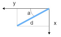
I want to be able to know the position in my soft robot in the 3D space, and among others recover its curvature. For this, I make the following big approximation: the soft robot can be considered as a line.
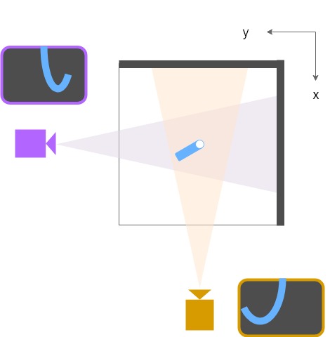
Based on 2 perpendiculars images, it is possible to compute the position of each point of my soft robot line: d2=x2+y2 and a=atan(x/y).
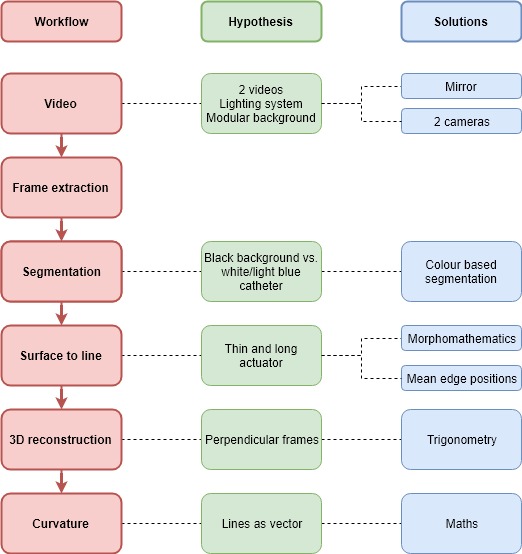
Here is the workflow I imagine to do it.
Resources and first tests
I also want to use photogrammetry in python, that I find readable, easy and efficient.
After searching a little bit through the internet, I found 2 interesting libraries:
And some useful tutorials: * Real-time lane finding * Real-time edge detection using Canny edge detection method * OpenCV
I create a new git repository on the ULB fab lab gitlab, to manage the versions of this project with Git. I will use the python user interface jupyterlab .
To open it, simply use the command jupyter lab. You can then access the interface via you browser.

Just adapting this tutorial to my video, I already have encouraging results!

This is to be continued…
Update week 12: improving the tracking and reconstruction program!
More than the control board, this week was dedicated to programming, and to extract the curvature radius from a test video of a catheter. Here is a schematic of the implemented workflow:
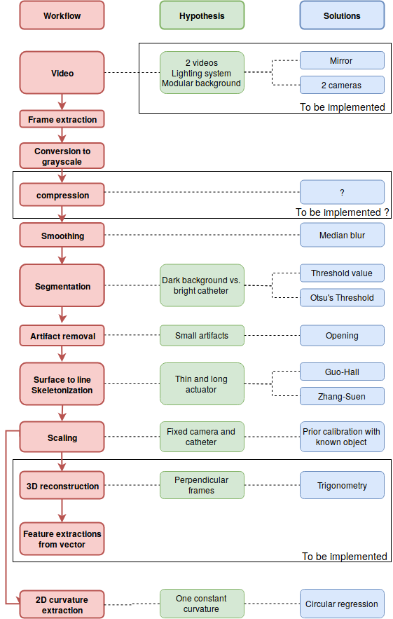
The implementation of the workflow used the open source library OpenCV. The two main sources were the following:
As shown on the diagram, not all the process has been implemented. However, as shown on the image below, the skeleton extraction has already been done! As a reminder, the big hypothesis here it that the catheter is considered as a line in the 3D space, so this skeleton extraction makes sense. Once all to coordinates of the skeleton have been extracted, I basically have a vector, and can imagine to compute almost any information from it (curvature of each point, position in 3D space, …). However, for the moment, and for the demonstration, I only worked on a 2D video. From the skeleton, I extracted the best fitting circle, which is a way to compute the radius of curvature of the catheter:
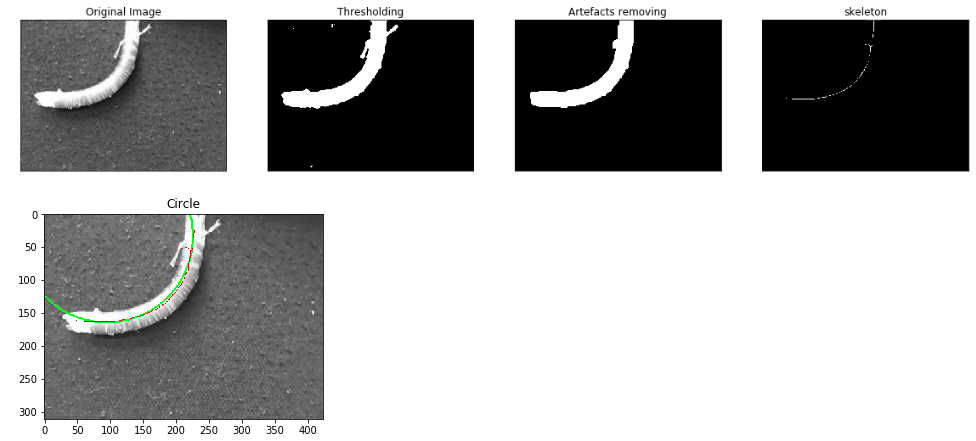
Concerning the scaling, I made a small algorithm allowing to compute the scale factor in mm²/pixel, by taking a picture (without moving the camera) of a rectangle of known size.
I implemented 2 solutions for the segmentation: using Otsu’s threshold or using a threshold based on a gray value. Even is the first one is more adaptive, it is an iterative algorithm, and consequently increase strongly the computational time.
Several limitations remain however:
- The program has only been tested on one test video. In particular, the capacity to handle other artifacts, or scenes with other illuminations could be problematic. A priori, the best solution will be hardware, by ensuring that the captured video can be exploited
- The synchronization of the frames with other data (typically the pressure) is not yet considered.
- Several parts of the workflow must sill be implemented.
- The computational time is for the moment a limitation. Two steps are limiting: the skeleton extraction, and to a lesser extend the smoothing/segmentation. Since it is difficult to modify those algorithms, two solutions can be considered: even trying other algorithms, even compressing the images at the beginning of the workflow (by reducing its size and/or quality). This will need to be tested, to ensure that no information is lost.