Final project - pressure control
Files and resources
Conceptual design
My pressure control board will be mainly inspired by the soft robotics toolkit, on which two solutions are documented:
The aim of my project is to have something similar to the complete board, but taking also inspiration from the low-cost version. Here are the main requirement for the pressure control system:
- 3 Channels with independent control
- To possibility to control air pressure with a precision of 0.05 bar at least, between 0 and 1 bar.
- An interface with a computer with a feedback on the pressure
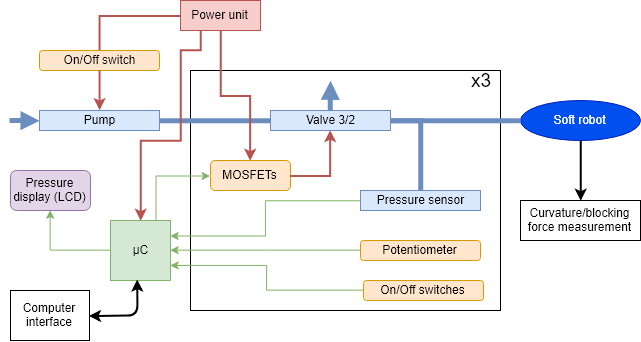
Here is a diagram of the designed system:
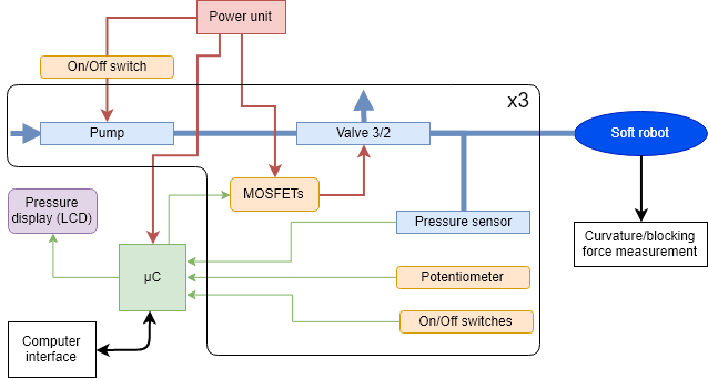
The blue parts are related to the pressure, and the yellow ones to the interface. The microcontroller would be connected to a computer to control the board using an user interface. The pressure value display is optional here (it would allow standalone operation, i.e. without connection to a computer).
Bill of materials
Note that the commercial verison is sold 959$.
Prototyping
Microcontroller
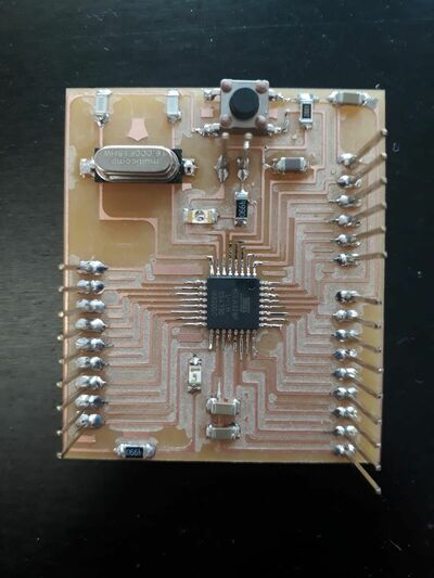
I want to be able to make multiple prototypes of the control board. As Denis did, I will follow the Stashakit tutorial, to make my own modular board. The fabrication of the board is detailed in week 11.
Measure of the pressure
Note that all the codes and complete documentation of this section are given in week 11 documentation
Sensor
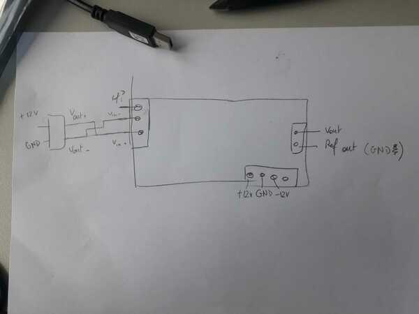
First, let’s take a look to the datasheet. The sensor has 4 pins: 2 for the power supply and 2 for vout+/vout-. As a first test, I simply connect a multimeter to Vout+/Vout-. I can use a 5V input or a 12V input. The second solution is preferred since it increase the sensibility to approximately ~10 mV/bar. The ADC of the ATMega328P works on 10 bits, i.e.1024 levels. If Vcc = 5V (which is the case), each I can measure 5V/1024=5 mV. This is not enough to have a good measure of the pressure!. I’ll need to amplify the signal!
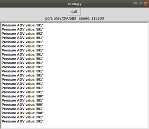
Let’s test the ADC of the board! I connect the outputs of the pressure sensor using a breadboard: Vout- to ground and vout+ to the ADC, and I use a multimeter. Even if the variations are really small, the value given by both the multimeter and the ADC are coherent, good! Note that all the codes and complete documentation are given in week 11 documentation
Amplification
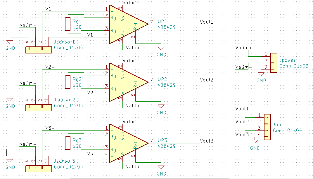
As explained above, I need to amplify the signal. Since the output of the pressure sensor is differential, I will use an instrumentation amplifier. Hugo, one of my colleague, already designed boards. It uses this amplifier. So I will adapt it for my needs. Here is his schematic (different gain are prepared, that can be changed using a jumper):
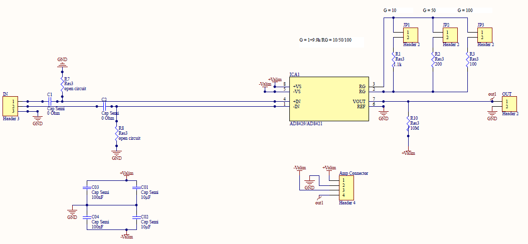
I designed it to remove the input high pass filter, and to have a gain of 100, i.e. using a 100 ohm capacitor. The gain can easily be adapted by changing the gain resistor.
Testing it, it works! I now have a signal of the order of magnitude of the volts! I can now design a PGB to have a proper circuit!
Other inputs
Switches
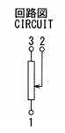
Same with the switch (datasheet). Here is the schematic:
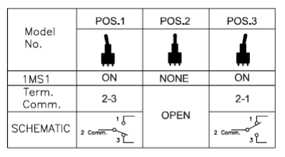
I connect pins 1 and 3 to the ground and Vcc, and pin 2 to my board. It works with the multimeter, and also with my board! Here is a nice tuto on how to use a button. Basically, you just need to set the digital port as input and read the value.
Potentiometers
Let’s add the potentiometer (datasheet) to the board. Here is the principle schematic: the pin 2 moves, and the voltage measured on pin2 varies between the voltage of pin 1 and pin 2.
I connect pin 1 to ground, pin 3 to Vcc, and checked with the mulimeter: it works! To read the value with the microcontroller, I just have to add another ADC input and precise which pin I want to read in the loop.. And it works!
Pressure source
Note that all the codes and complete documentation of this section are given in week 12 documentation
Pump
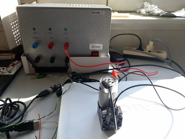
The pump that I use is quite plug and play: connect it to 12V, and it works! I’ll just need to add a switch in series of the pump to be able to turn it off and on easily.
valves
The same is true for the valves! I ordered a 3-way valves normally closed, meaning that the input can be connected to one or the other output depending if the valve is powered or not. I first connect it to the 24V power source as the pump, and it works I hear a “click” when I turn on of off the power. I then try the same connecting the valve to the pump, and I can now feel the air flowing trough one or the other output!
MOSFET driver
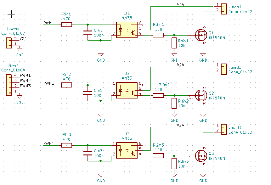
The valve must be powered on 24V, and must be controller using PWM to control the pressure: I need a driver to interface it! As explained above, I will try to redo this yourduino board, a little bot modified. Here is my schematic:
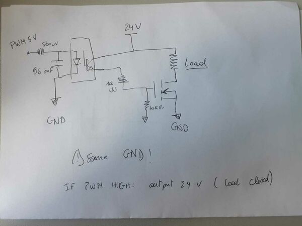
The principle is the following: the input is the logical (0/5V) PWM signal generated by the satshakit. The optocoupler will isolate it from the power. At the output of the optocoupler, the voltage is already 24V, but the current that an flow through the optocoupler is too small to power the valve. The output of the optocoupler is then used to drive the MOSFET (that can be seen as a current switch controlled in 24V). If the MOSFET is “open”, the load will be connected to the ground and current will flow trough the load and the MOSFET, otherwise not.
I made the board on a breadboard and tested it with a 5V power source and a manual switch at the input: it works! And testing the valves with the pressure source : it also works as expected!
PWM
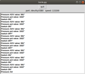
I am now ready to use the satshakit PWM to drive the valve. I worked using this tutorial as well as the ATMege328P datasheet. Here is a short video (be careful for your hears..):
PCBs - Second version of the prototypes
PCB design
Pressure Amplification
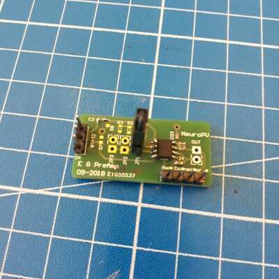
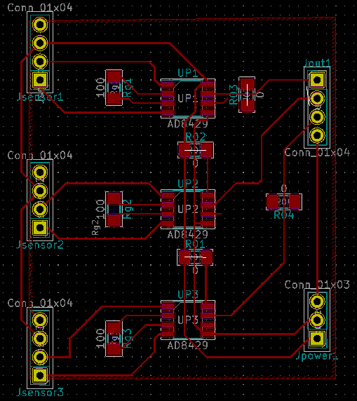
I made several PCBs modules to clean the electronics. The first on is the amplifying circuit for the pressure sensors.
The alimentation voltage can be +/-12V or 5V. I chose only one voltage for both the pressure sensor and the op amp to make it more simple. 5V ensure the output to be limited, while 12V would increase the output signal of the sensors. The value of the resistors can be changed to adjust the gain! On the PCB, I added some 0 ohm resistors for the connections and a ground plane.
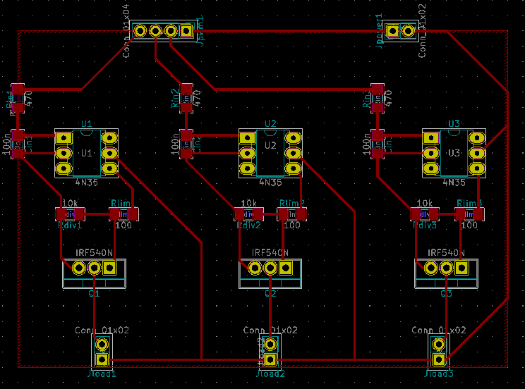
Valves driver
Same for the valves driver:
Testing the PCBs
I am ready to put all my boards and components together and test the assembly! First, let’s clarify how I’ll use the pins of the ATMega328P.
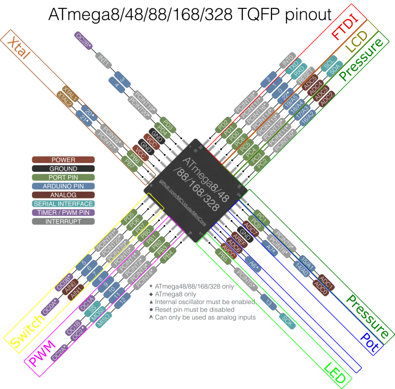
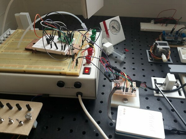
Note that I now use it as an arduino board! It allows me to use a whole set of libraries and a simple language… It’s a relief! I can also assemble the pressure circuit as described on the conceptual design. Several points are still simplified: only one channel is implemented (and not three in parallel), and the switched and potentiometers are not considered yet. More, the pressure is only controlled in open-loop. Indeed, the sensors are not calibrated yet. Finally, I can use my demonstrators.
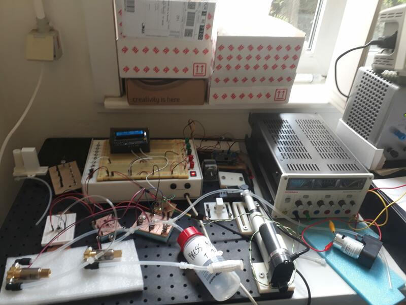
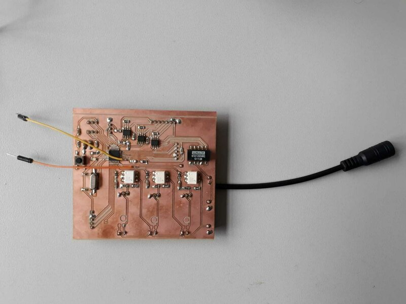
Here is basically how it looks… Just a little messy!
A key point: controlling the valves and the pressure
My first choice is to set the PWM frequency at 30 HZ, i.e. using the 1024 timer divider of the ATMega328P. Varying the duty Cycle, I can easily obtain pressures between 0.05 and 1 bar, measured with an analogic pressure sensor.
But, I have a problem: When I measure the voltage across the transistor with an oscilloscope, I see large voltage peaks that appear! At the opening of the valve, the power between the ground and the drain raises to approximately 120V… Way too much! After discussing with some colleagues, the problem is probably due to the inductance of the valve. The solution was quite simple: Adding a diode in parallel with the valve solved it! I used a 1N5394 diode that I add in stock! The only requirement for the diode is to be able to survive to a sufficient backwards voltage (>120V). The diode is placed from the drain to the 24V power line, to allow the inductance of the load to discharge when the transistor is open.
But, I have another problem: with the tested pneumatic circuit, there is a lot of noise on the pressure signal! The pressure oscillates quickly, at 30Hz, and of a non-negligible amount! First solution tested: increasing the PWM. To do this, I first made some bitbang test, following the simple example here. The results are not very encouraging: above 40Hz, the valves cannot switch anymore, there response time is too slow… The second (successful) solutions is to add inertia in the system, by adding “tanks”, large volumes (I used those kind of bottles, having a volume of 350 ml), in the pneumatic circuit. After testing multiple configurations, the following configuration works perfectly:
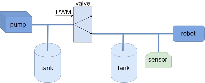
However, this has some drawbacks: it is quite bulky, and reduce the response time of the circuit. Other solutions would be fast switching valves, or a better pump.
When testing two channels in parallel, the output pressure is lowered for the same duty cycle of the PWM, but it still works good! But I’ll have to be careful, because I also noticed a lot of coupling between the different channels… As a backup solution, I can still add more pumps in parallel, i.e. make 3 really separated circuits.
Amplification and pressure sensors
The input board, for this tests, was powered with +/-5V, and not 12 V as in the first tests. Good news, it worked directly! However, the gain could be increased, less the signal being of approximately 0.5V at 1 bar with a resistor of 30 ohm. This will need to be adjusted for the final board!
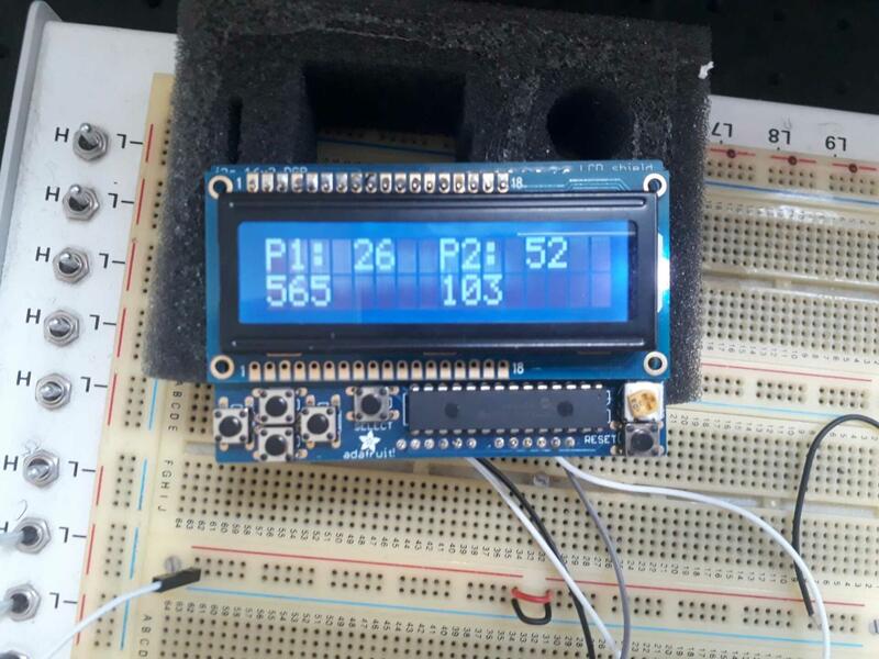
Adding the LCD…
The LCD was also added, quite simply, to the project, as documented in week 14.
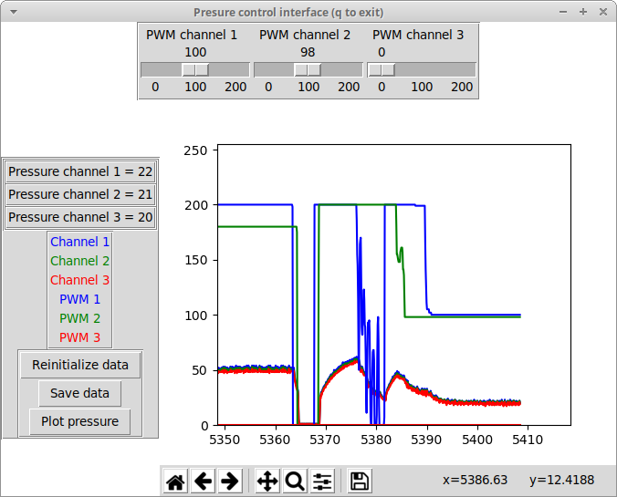
And the interface
The first version of the interface was also developed at this stage. This is fully documented in week 16.
Final pressure system
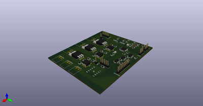
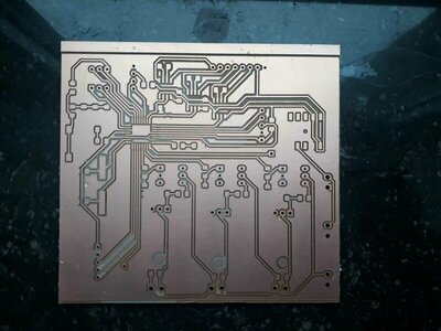
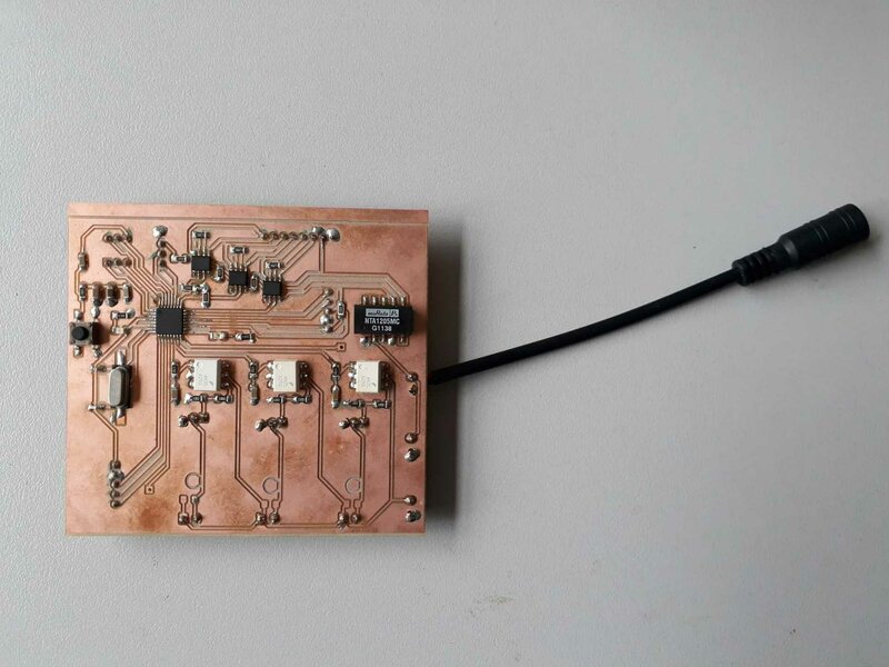
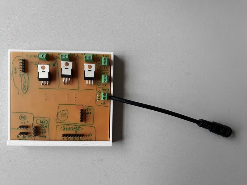
A clean and integrated PCB
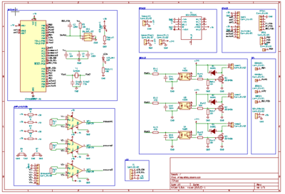
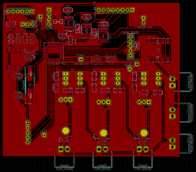
Based on the prototyping described above, I made a clean integrated board including:
- The satshakit base (i.e. an ATMega328P with a 16Mhz crystal)
- The acquisition chain described above
- The PWM driver also described above
- A power management system described below
- Connections to the LCD, he FDTI cable, the switches and potentiometers,
(you can click on the schematics and pcb layout images to show the pdf)
Power management
Concerning the power management system, I need -5V, 0V, 5V, 12V and 24V, with enough power… not easy! Seeing the availability of the converters: I choose the following configuration:
- A 12V and 36W power supply is used to power the whole system
- A PCB mounted converter is used for the low-power +/-5V
- An external converter is used for the 24V
Note that all the grounds are connected together.
Adjusting the board
On the implemented version of the board, I forgot the SPI connection to program the board an burn a bootloader on it! I welded some wires on it, but this was not very practical… This is corrected in the files above!
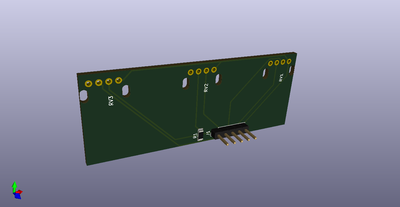
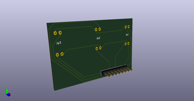
Pressure sensor board
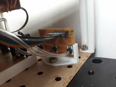
I also made a small PCB to fix the pressure sensors and the potentiometers= two very simple input board to avoid a bunch of wires (all the files can be downloaded at the top of the page).
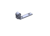
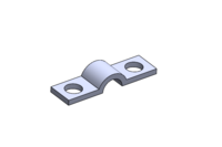
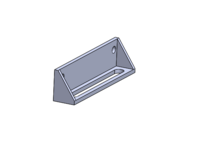
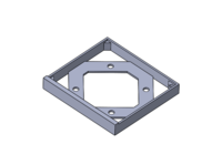
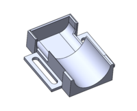
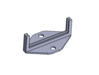
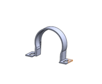
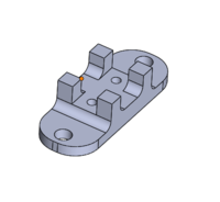
Supports and embodiment for the components
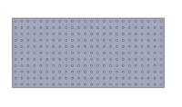
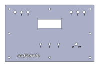
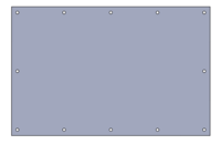
Another important and not that easy part was to make a support or a box for all the components. Indeed, there are a lot of them electronics components as much as fluidic components… Since I made my prototyping on optical breadboard, I decided to keep the same principle: 6 mm holes in a plate spaced of 25 mm each. Those standard values allowed to easily make separated supports for each pieces, fixed with M6 bolts and nuts. The disadvantage of this solution is that the compactness of the components is not optimal. The size of the support is 275 mm x 600 mm. To hide the components and protect the electronics, I just made a second “top plate”, with holes and places for the potentiometers, switches, and LCD. Finally, I made vertical supports for the top plate of the box.
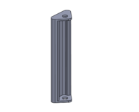
As I said, I also made individual supports for each components. They are fixed using M6 bolts and nuts.
And here is a video of the assembly:
The assembly can be placed on a fabric sheet to reduce the noise and vibrations.
Programming the final board
Last but not least, the pcb must be programmed. I used the same protocol than in week 14, to use it as an Arduino. It is basically just what was done in week 11 for the inputs, week 12 for the outputs, and week 14 for the communication with the interface, gathered in one code. The code itself can be downloaded from the top of the page.
A key point was to calibrate the pressure sensors. To do this, the pressure mas set manually with a syringe, and measured in parallel with an analogue pressure gauge. A correlation was drawn using Excel, the file can be found in the downloadable folder.
Further improvement
Of course, this work could be still improved! Among other, lets cite that more performant pumps could allow to increase the pressure (the max pressure is now around 0.7 bar, and small leakage is required to avoid a too large inertia of the system when depressurizing). More, the communication between the board and the interface could be improved to develop the possibility of a real control of the pressure.