14. Networking and Communications
Serial Communication protocols
This session is very valuable, that includes a lot of data and behind every word a big world!
I understand that, It’s so hard to be aware with all the content of the session or 30% of it!
I tried to do my best to get the most of the point in this topic. Also, Kamel did that! he reviewed the session again with us and tried to explain everything with a simple way. I know I didn’t get all points, but I totally convinced that will be the start to learn more in this topic in the future!
Some notes during the session
We’re already working with communication from the first week of electronics, but we didn’t hit the spot for this is called communication!
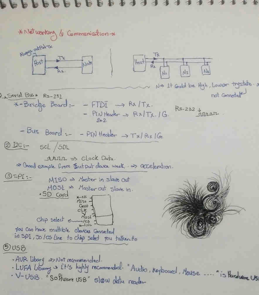
The ISP headers that we are using is one of the serial communication protocol … that we used
- MOSI’ Master out slave in’
- MISO ‘Master in slave in ‘
- SCK ‘Clock’
All of this pins that handle the serial communication protocol between two boards or more.
So this is communication.
Also, The FTDI that we are using … Tx and RX … this is serial protocol… asynchronous serial protocol.
So, all of these is different protocols that we decided to use one of them depends to our project needs.
After our discussion we decided to use asynchronous protocol for this assignment. That we need one master talks to multi nodes depends on their addresses.
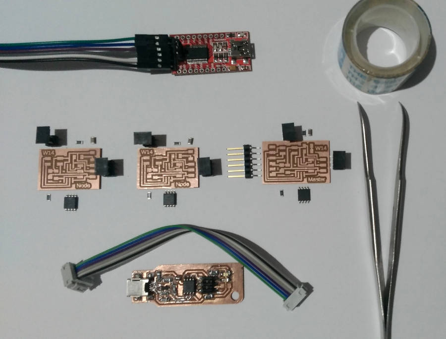
The Asynchronous Boards
To make asynchronous serial protocol, We need per minimum
One Master board or sometimes called Host that send data to the node board and One Node Board that receive the data from Master with a specific ID address
So I decided to make a bus addresses with one master board and two node boards
My reference here is Neil’s board
-
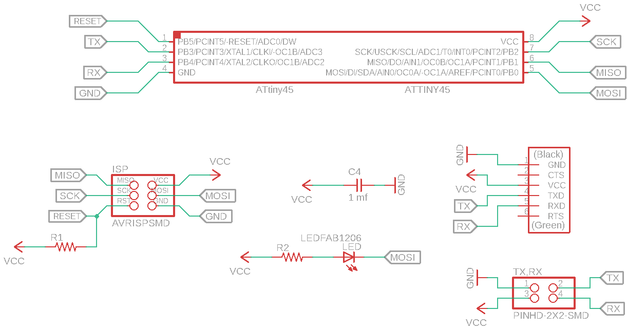
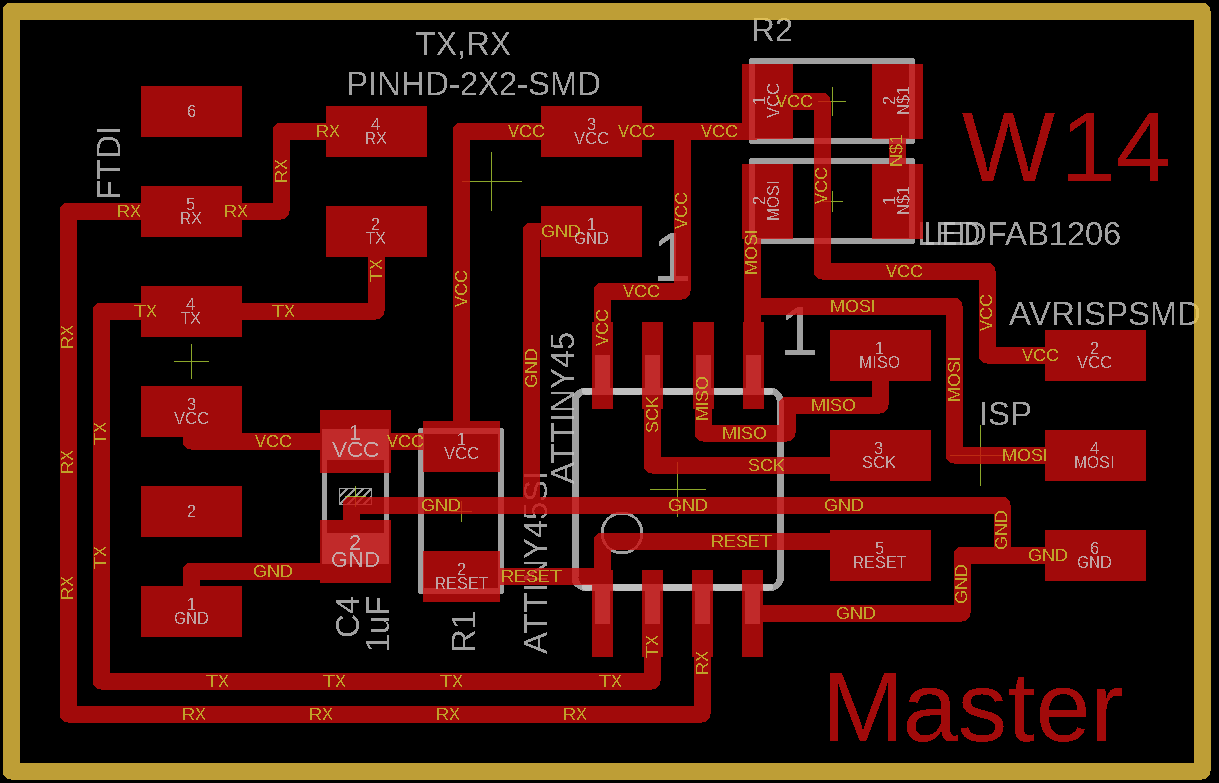
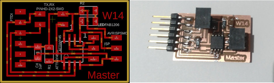
So, This is the first board, Master board
-
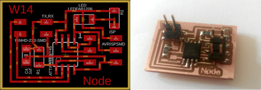
The second board, Slave board
After reviewing the two boards, I noticed that
- We used attiny45, we don’t need a big memory for this process.
- We used the same boards with the same compounds but the difference in the master board have FTDI headers, to be able to communicate with our PC.
- We will connect RX in the Master board with the TX in the other two nodes, Also the TX in Master with the RX in the nodes.
- Actually I prefer to say Host not Master… Because or the reality is the Host board is considered as a node board with the PC … I know it’s confusing but when I’m thinking in this point, the host board actually has an id address and communicate with FTDI cable with TX and RX too … So it’s also link between two nodes and serial monitor.
Redraw the Boards
This week I wanted to try a new tool, I wanted to do this step from the first week of electronics… So Let’s take the chance!
Started with KiCad, I don’t have tutorials to learn easy… So I decided to discover it!
Just installed the software, Then I wanted to install fab library in KiCad as we did in Eagle. So I asked my reginal classmates, Babken from FabLab Dilijan has been worked with KiCad. So he recommended to read his documentation.I started from here.
But after two hours, I preferred Eagle. So I back to use Eagle again!
For this week I thought the boards is very easy and small … It’s the same almost… we just add the FTDI headers in the host board.
I started with the host board, while I finished it I copied the file and removed the FTDI headers from the PCB.
Host Board
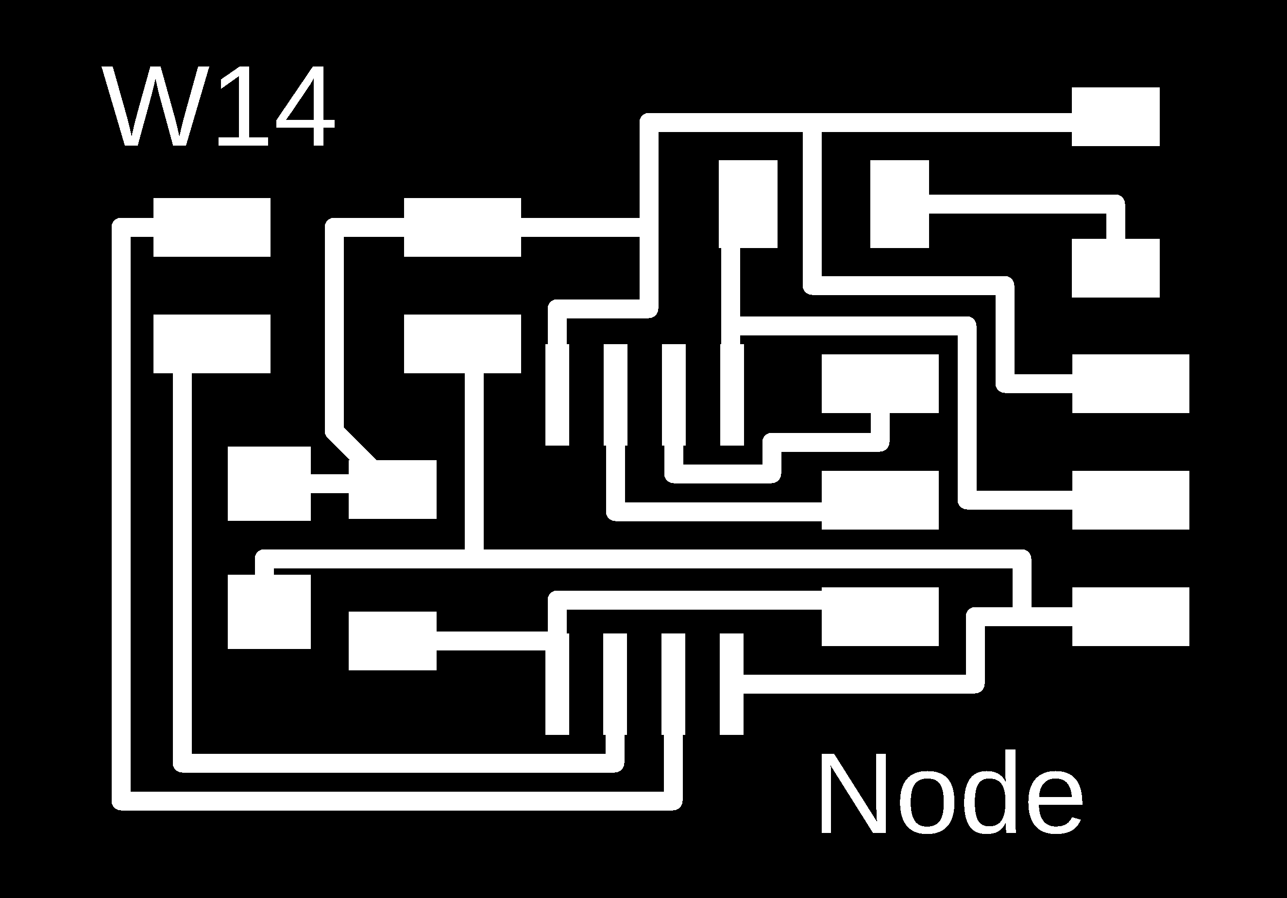
Node Board
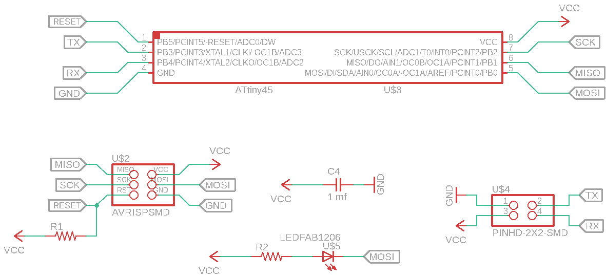
Photo editor
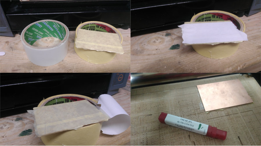
- Base


For this stage, I think about How can I save my time!
To make three boards in the same time … if we make one by one we need to change the endmill about five times … also we need to setup the coordinate points for three times and edit the Z position…
I imagined all this scenario … So I chose to spent a little time to edit my three boards in one board to reduce the machine time.
What makes me think by this way … My discussion with Mahmoud Kotb in the Molding and casting week … when we took about save machine time to get the same result that you want…
So I edited my images again… Then I followed the same steps that we made in first week of electronics
Revision 0
Photo editor
I used GIMP editor… it’s very easy to learn

Now we have all boards in one process
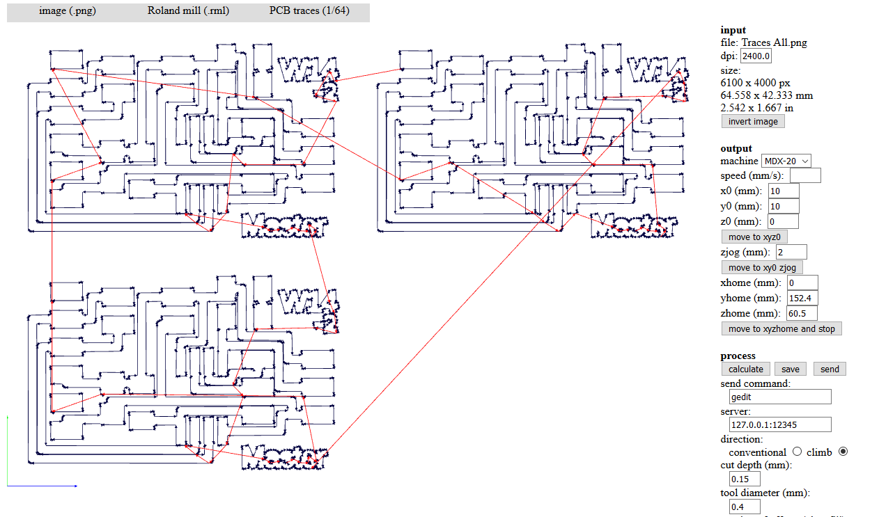
Fab Modules
Everything looks fine, So we can start!
Fabrication
My big deal with this machine is the Z plate… I tried a lot of variables of cut depth as I have made before, but it’s not logic to make the cut depth to .28 and still draw … So I asked Kamel, he noticed that, the PCB sheet not good!
So we need to change it… also to make sure I changed the base plate… I used wood..
Revision 1
First I want to make sure of the board dimension is fitted with my board
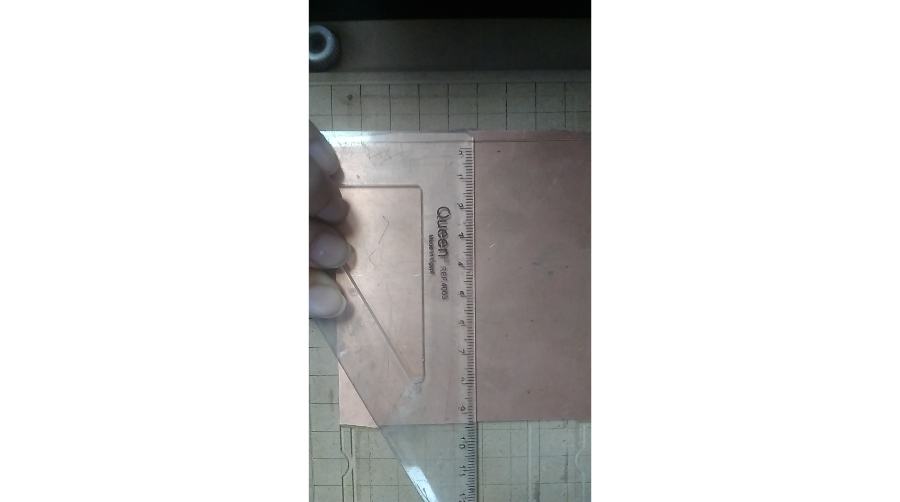
From the fab modules, the dimension of my board about 92*20.6 mm … and my stock here is 94mm … I want to be in the safe side, So I need to make some edits to reduce the width again.
Photo editor


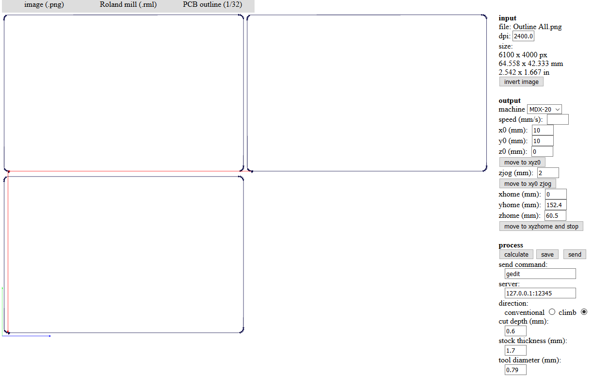
Fab Modules

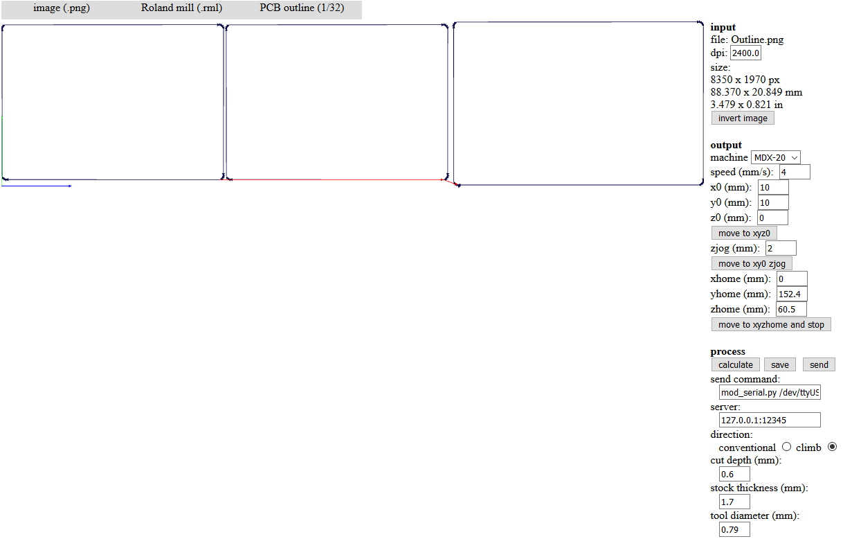
Now, my board dimension about 88.4*20.6 mm..
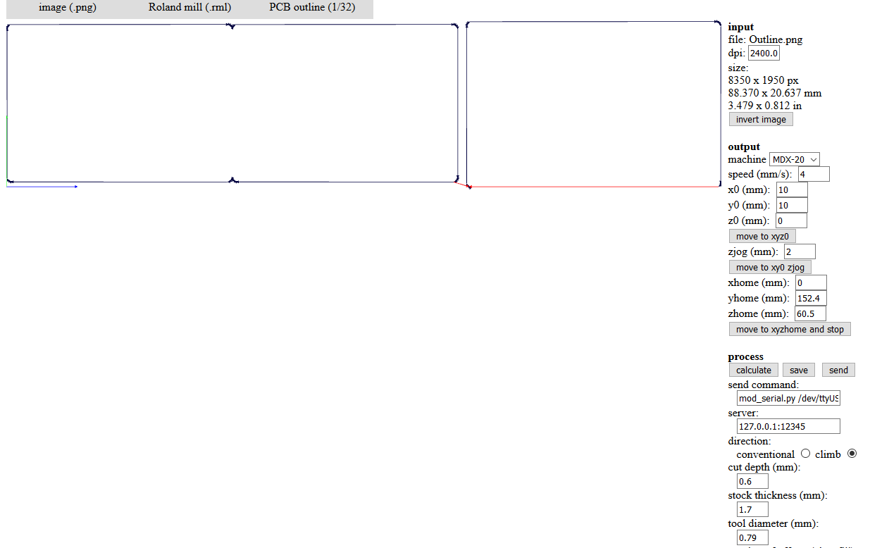
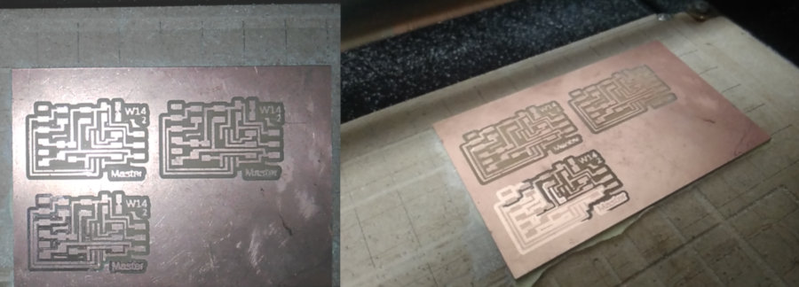
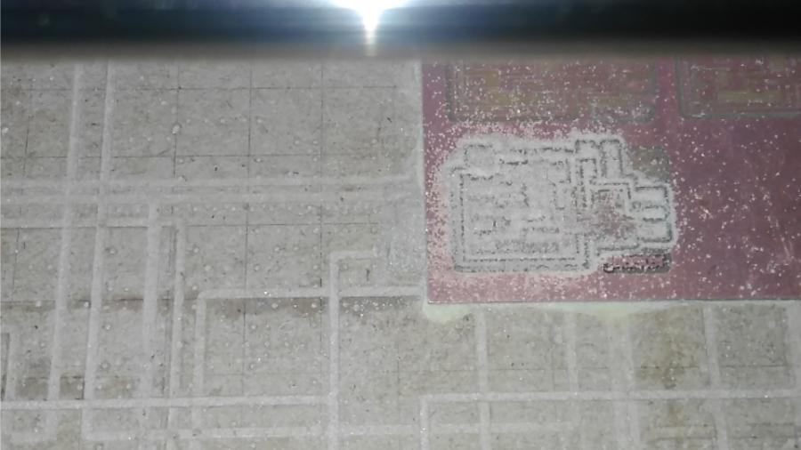
We noticed that there are three lines didn’t appear… the two lines between two node boards … also the down horizontal line of the host board…
Then I made some edit that Mahmoud Abo Elnaga learned me before in advanced maker diploma… we can reduce the tool dimeter ‘with limit’ in fab modules to calculate the whole board… This issue happened because the two board is very closed from each other … so the tool path can’t define the two different colors between them… So when we reduce the tool dimeter we helps the tool path to see the whole board.
I know this is not a right solution but it works in some cases!
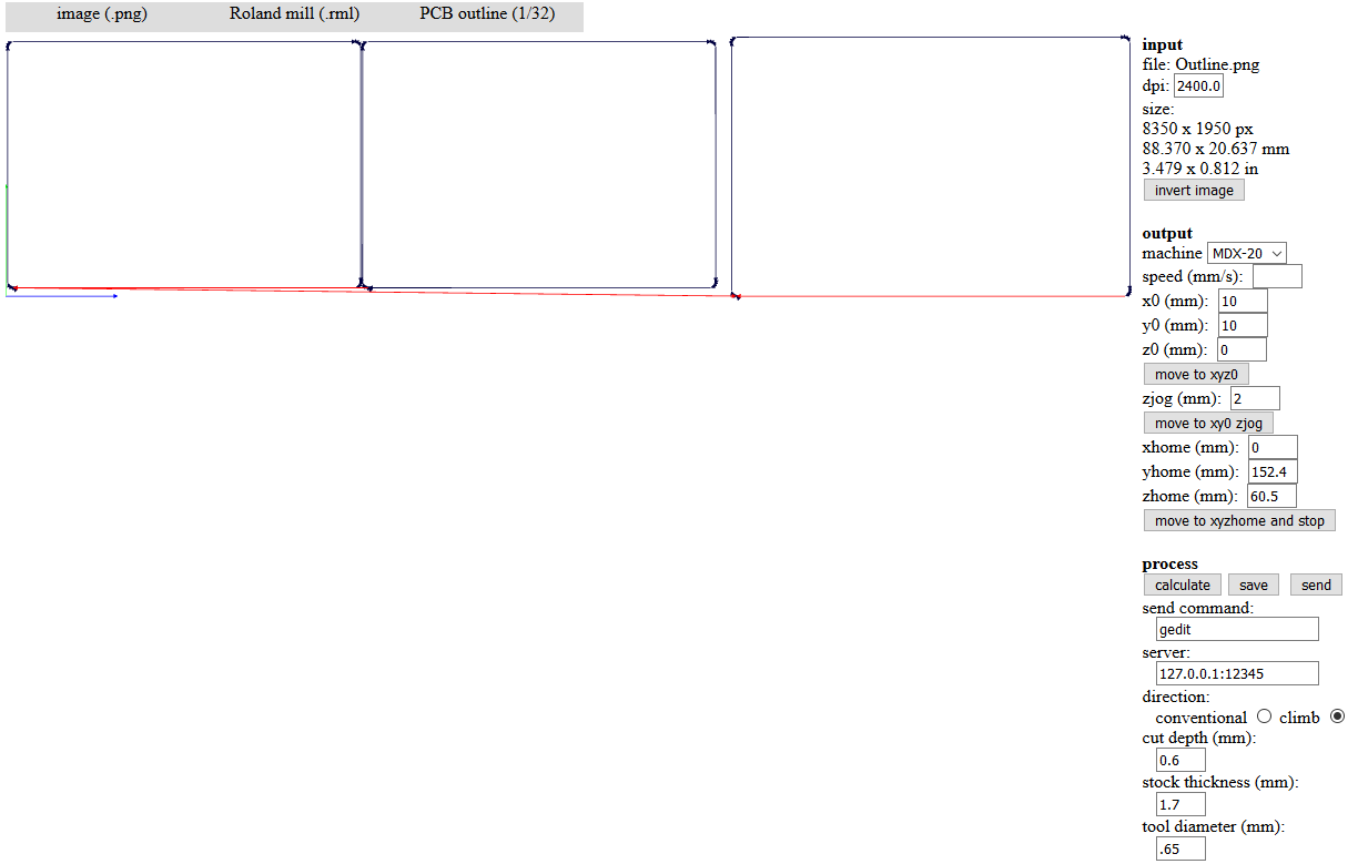
So this image after reduce the tool dimeter from 0.79 to 0.65. the two lines between node boards appeared but the third line don’t.
So I back again to edit my images … Then this is the result.
Now we can start!
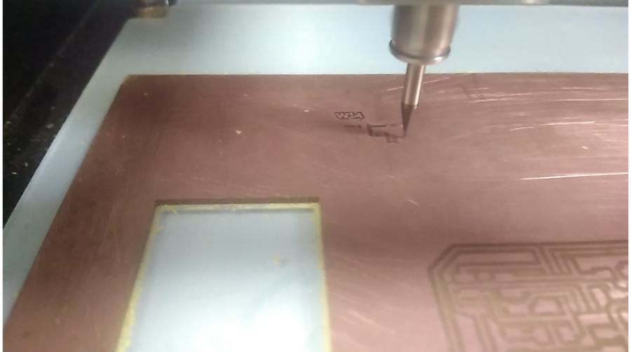
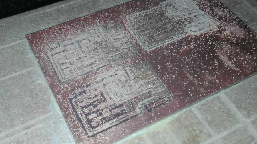
Fabrication
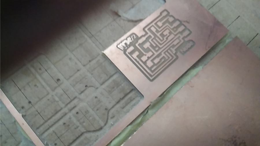
I faces again the Z plat issue … but I used cut depth .15 and it works
Finally, I have my three boards!
The fabrication Process takes 20 min.s for traces and 2 min.s for outline.
Welding
Big Mistake
I prepared my programmer to program my boards… then I shocked with what I have been made!!
I will let you with the picture to know the problem!!
Who made that!
I don’t know…
Revision 2
I will fabricate my boards again, because I tried before to de-solder the attiny45 … but it’s so hard also I don’t sure if it will work again after heating or not.
So, I will fabricate my three boards again…
Another challenge with board dimensions… I have only one size for FR1 board, is 52mm * 75mm … So I need to edit my images again…
I will make my three boards in one board again.
Photo editor


Fab Modules
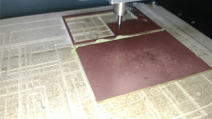
Fabrication
This way that I learned from Mahmoud Kotb to fix my board, The first time he fixed the board by himself to learn me… after that I fixed the board by myself.
Traces process for the three boards
Z plate error… So I re-traces process for the third board again
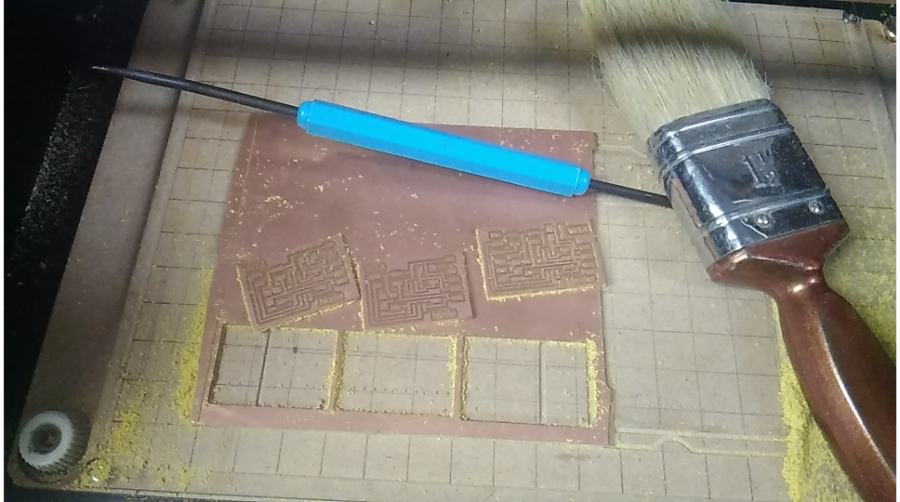
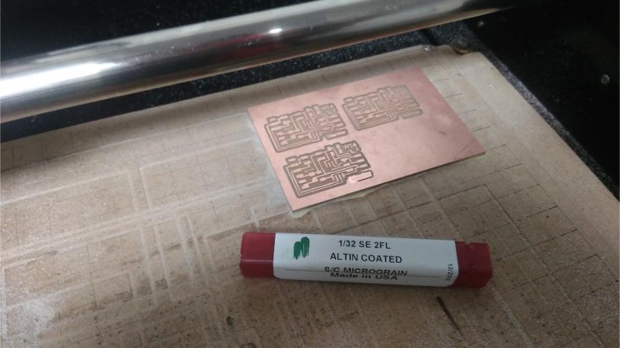
Change endmill to 1/32 to start in outline process
Clear and simply remove scotch from boards
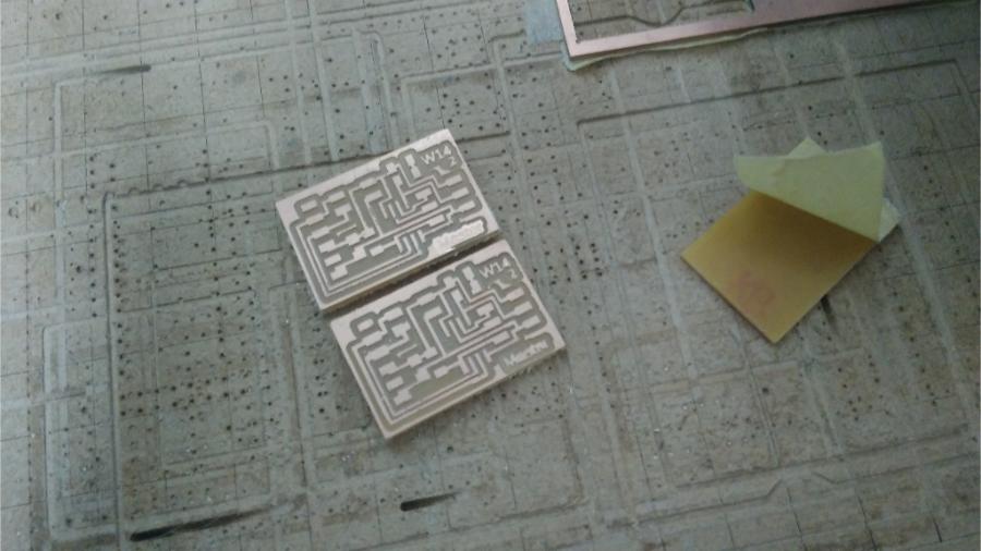
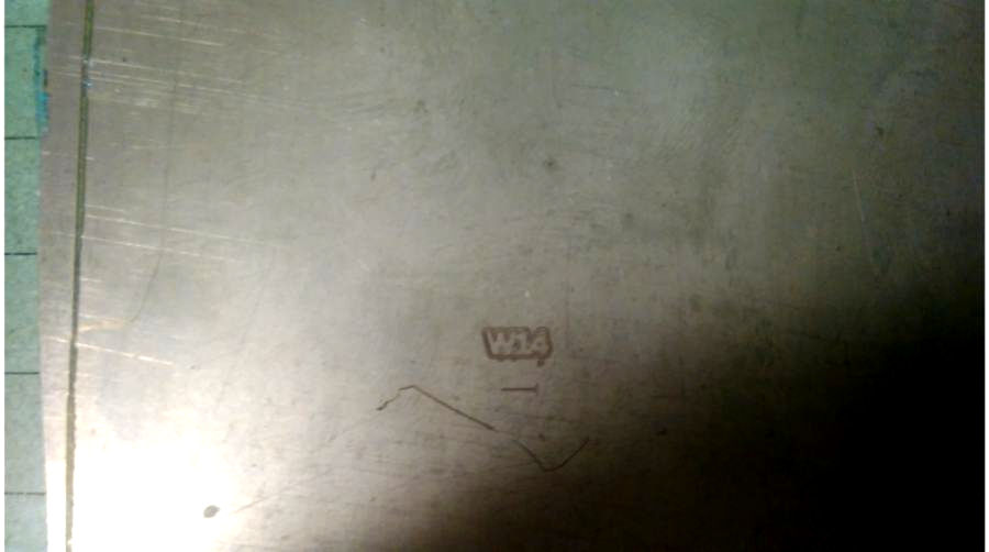
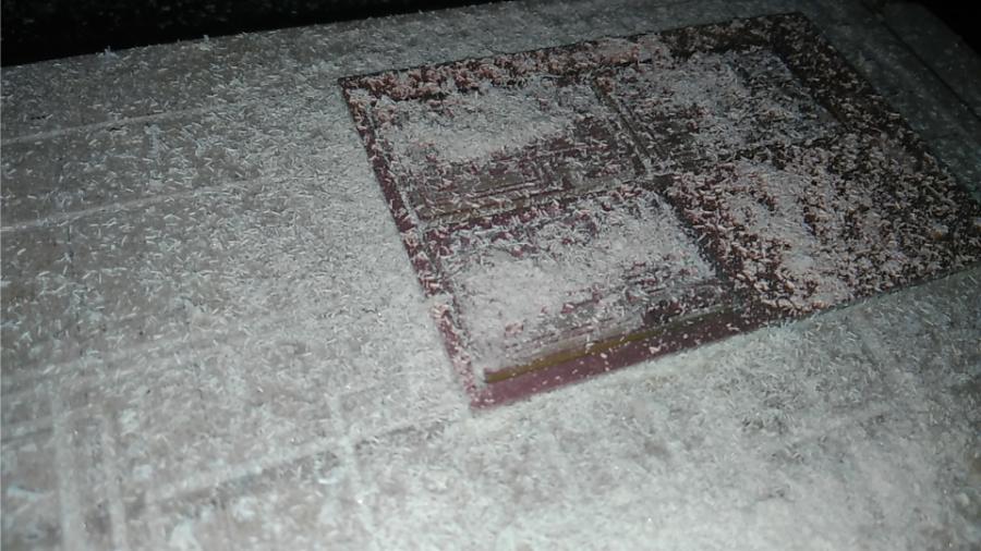
My Second Mistake!
Suddenly I noticed this image…
This is messy!!!
The three boards is Master! … I didn’t notice that when I edit my images or fabricate boards! all my attention to finish this routine process fast to start my assignment.
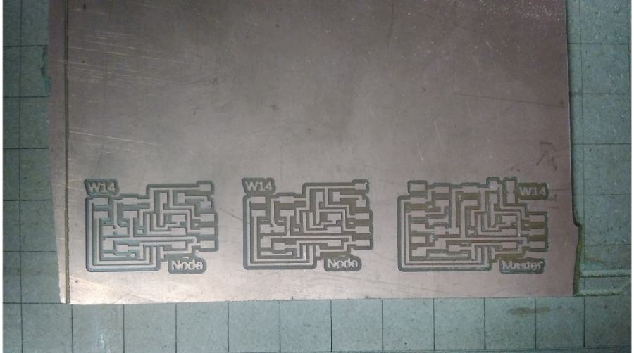
Re-Fabricate
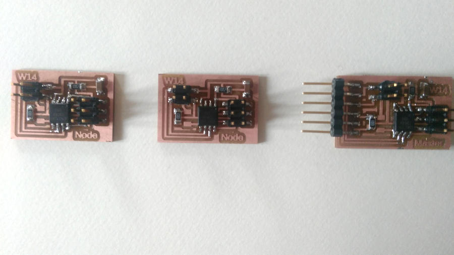
Three Boards
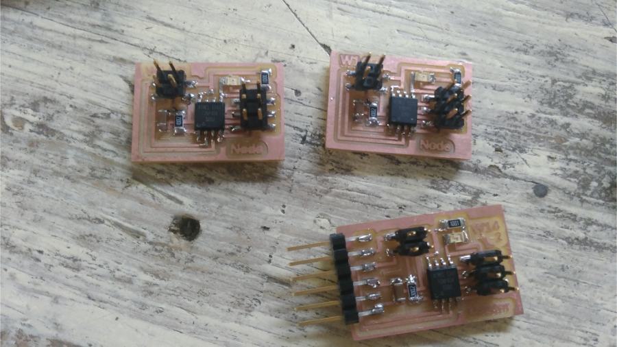
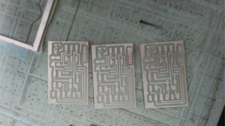
Finally!!
I have my last correct three boards, one host board and two nodes.
Now we can to start in next step.
Programming
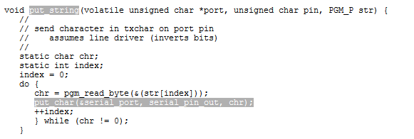
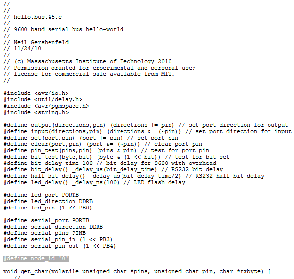
I started with Neil’s code, Opened the code and try to understand it.
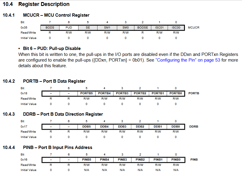
Then, these lines makes me opened the datasheet to read more about the direction, port and pins
#define serial_port PORTB #define serial_direction DDRB #define serial_pins PINB
That what Kamel was trying to explain to us.
Ports as General Digital I/O, Datasheet
From page 52 to page 63, So review these part is very important.
- Test pin loop

- Put char
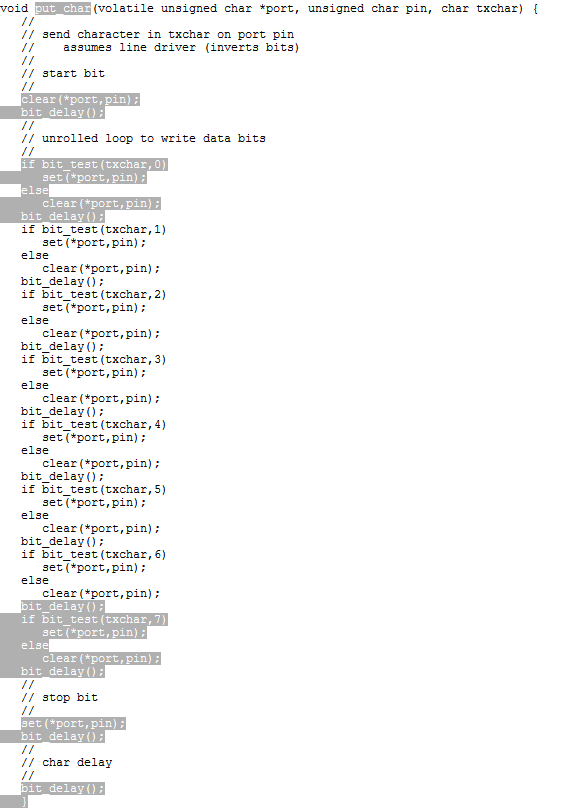
- Put String
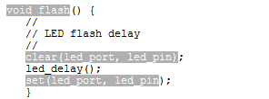
- Flash LED
- Int Loops
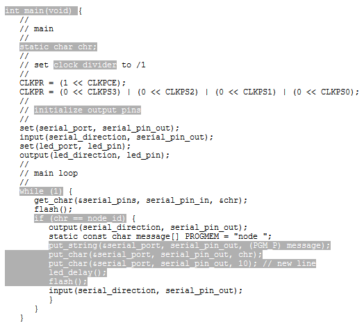
Board address
So we used the same code for the three board ‘Host Board and Nodes’ But first we change the address of each one
#define node_id '0'
Uploading The Code To Boards
-
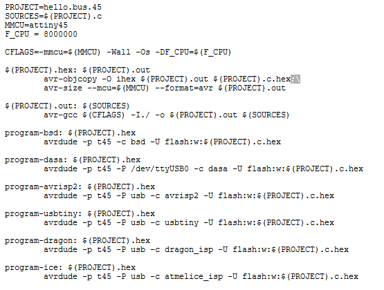
First, download the make file and the C code, hello.bus.45.c.
-
In case your system is windows 10 … you need to edit the make file
replace this line
avr-objcopy -O ihex $(PROJECT).out $(PROJECT).c.hex;\
with This
avr-objcopy -O ihex $(PROJECT).out $(PROJECT).c.hex
-
Then, we need to edit the board id for each board in the C code as I mentioned.
-
Connect the AVRISP for the board to AVRISP for your programmer
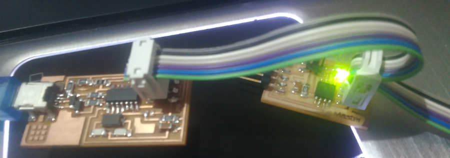
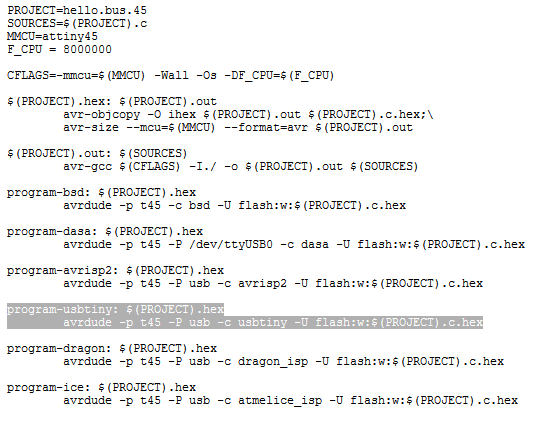
- Then, we open command prompt in the directory that we downloaded the files in, and Write
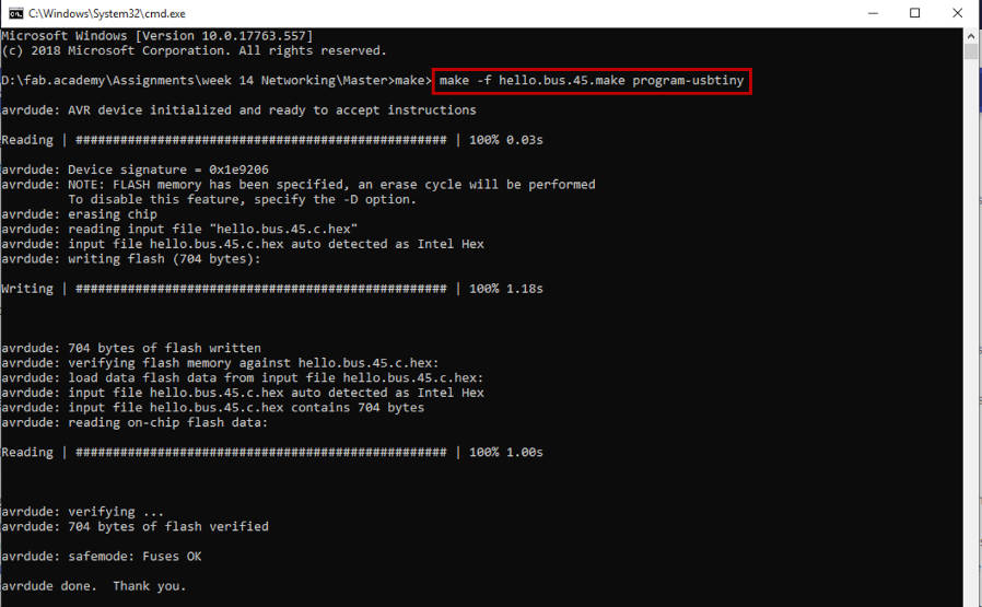
make -f hello.bus.45.make program-usbtiny
- -f to select the file that you need to maker
- hello.bus.45.make … you have to write the exactly name file without any changes
- program-usbtiny … the exactly function we need to do
Supposed, you see that…
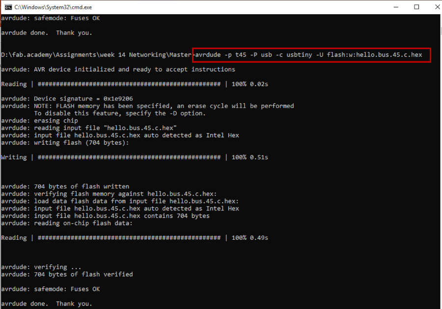
Then, Write this line
avrdude -p t45 -P usb -c usbtiny -U flash:w:hello.bus.45.c.hex
- -p to specify the type of avrdude ‘t45’, attiny45
- -p to specify the connection port … usb
- -c to select the programmer ‘usbtiny’
- -U to specify the memory operation
Congratulations! it’s done…
Then I redo the previous with the Node boards with change the id address as we explained
But I found this error
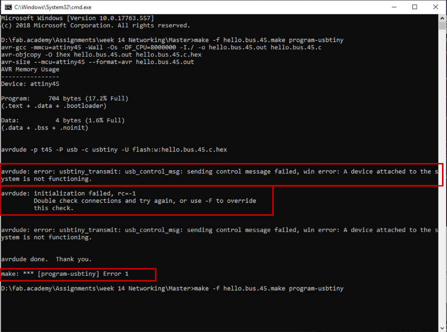
That because my programmer issue, it’s so weird… my device appears defined in the device manger … but my PC didn’t read it.
I disconnected and connected it again, also installed the drivers again as I did every time!
Then reprogrammed the node boards … and it’s Finally done!!
Now, the board is programmed.
Bus Serial Communication Error
For this step,
- we will replace the USBISP programmer with FTDI … we used the programmer to upload the code … but for this step we need to make serial communication between our boards and PC. So we need TX and RX in the FTDI to connected with RX and TX in Host board. Also with the Node boards.
- Open Arduino IDE then the serial monitor and writ 1 or 0 or 2
then show which board you will talk!!
Serial Bus Communication Error from Nada Gamal on Vimeo.
No one… just master!!!
It just flashed …
I don’t now the reason… So I redo the whole process again … and try many times… Then I got the point
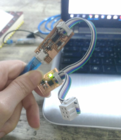
I made something smart!
I connected the ISP pin headers with each other to the three boards!
There is no serial communication will happen for sure :))
Bus Serial Communication
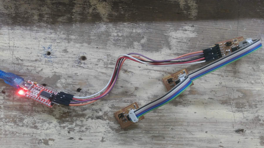
I reconnected the right pins of TX and Rx… and tried again …
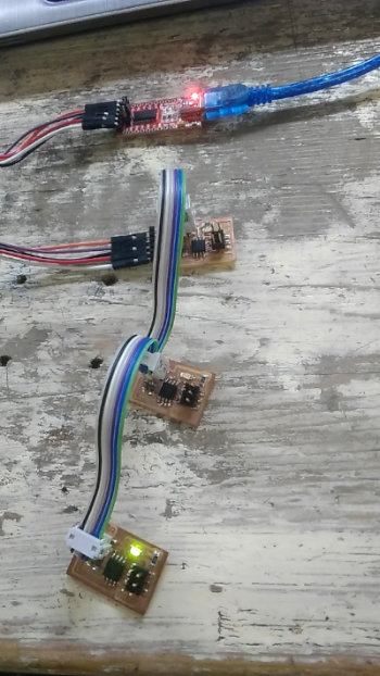
I have an issue with the second node … I really don’t know the reason… I make sure from the welding … programming … everything … but it doesn’t communication with the other boards…
Bus Serial Communication from Nada Gamal on Vimeo.
Enjoy!
Feel Free to Download Files
-
Eagle File
-
Host Board
-
Node Board
-
KiCad
-
PNG
-
Host Board
-
Node Board
-
Three Boards - Rev. 1
-
Three Boards - Rev. 2
This revision is wrong the three boards are master!
-
C code