12. Output devices
This week, I chosen the servo as output device for my board.
Draw the servo Board
Actually we have two different boards of servo. The first board have voltage regulator ZLDO1117 and the second board we have another voltage regulator LM2940 So I used the first board as a reference because we have ZLDO1117 in our lab.
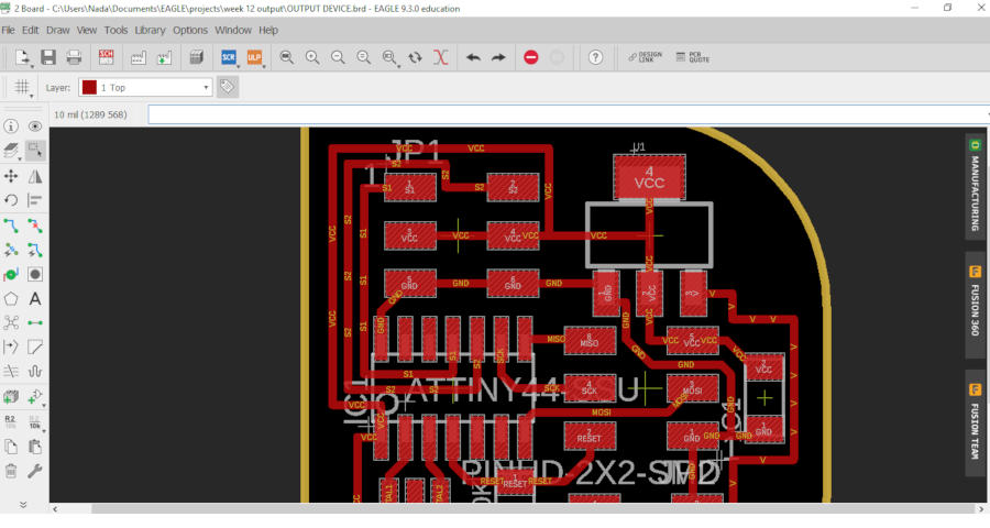
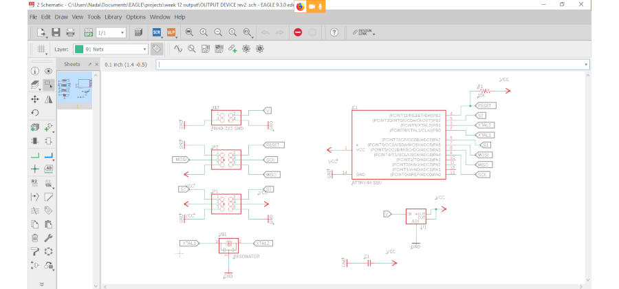
I used Eagle as usual to draw my board although I decided to try KiCad this time, but I didn’t!
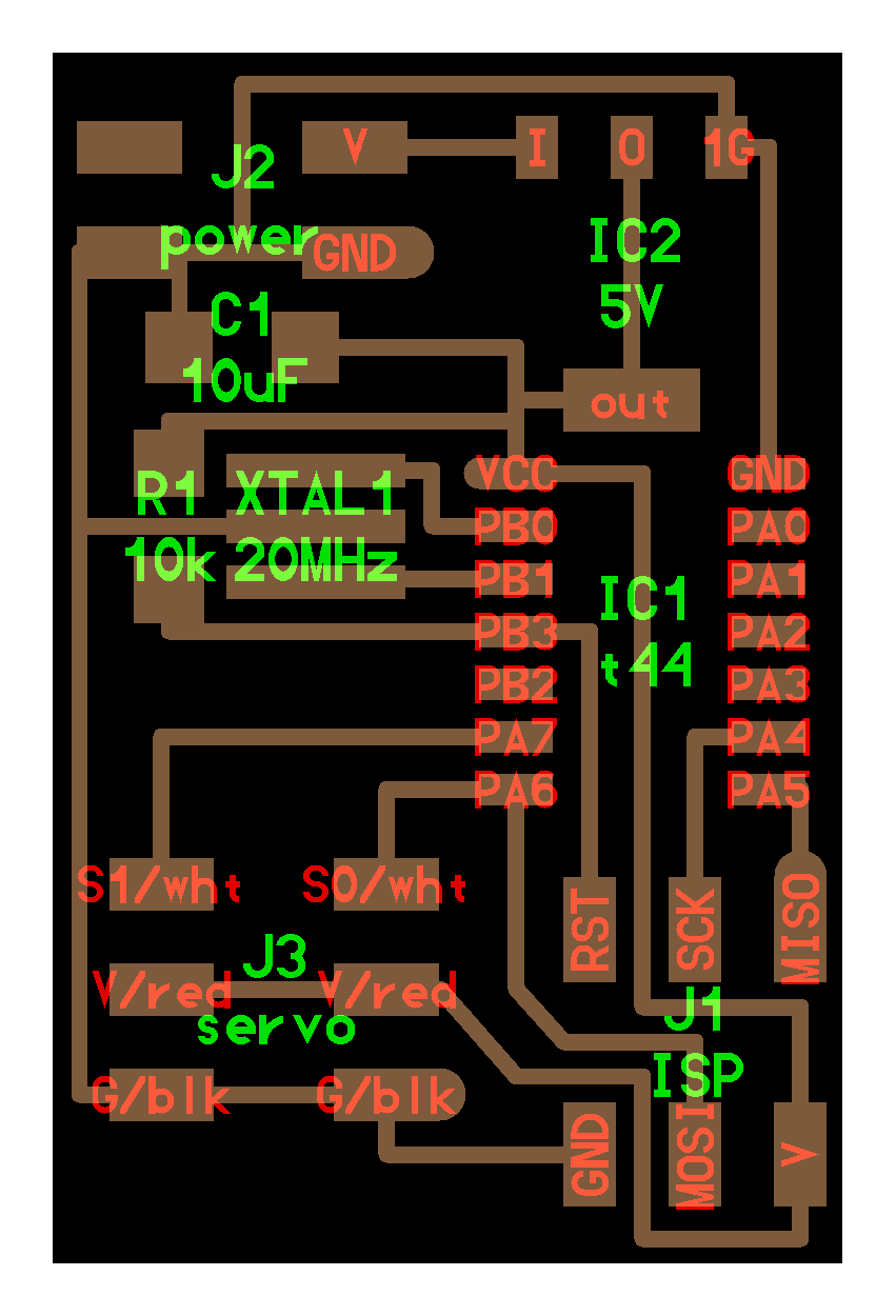
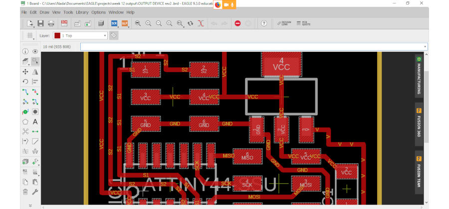
So I made the same schematic as Neil’s board but I have a problem to make the same traces from another board … So I connect my own traces … and that made me to change the servo pins. Neil used PINs ‘PA6 & PA7’ for Servo 0 and Servo 1. what made me not use the same PINs that I made this board in two stages … First the schematic and the second stage for the layout… So I forgot in the first stage to connect servo PINs with ATtiny 44! and imagined that I finished So Started in the layout directly. Then this is the result
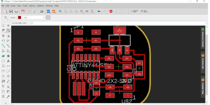
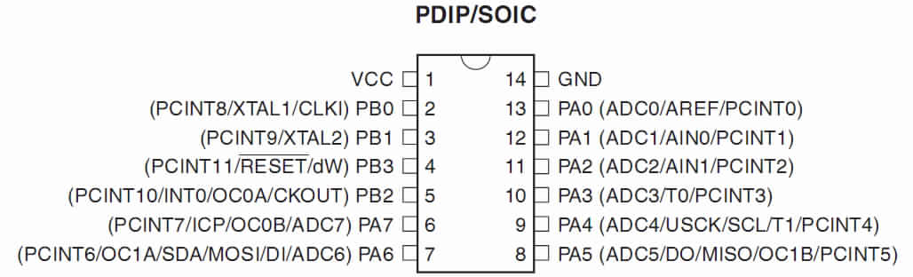
So I back to Neil’s board… I found myself will redraw the PCB from the first if I used the same PINs, plus all pins of attiny44 from 8 to 14 can use. So I searched quickly about attiny44 to see its PINs from this photo
As usual I prefer the below diagram for microcontrollers, you can see all pins here and analog or PWM pins… else.
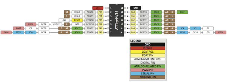
So that makes me confused and compare between attiny44 pins just PA and PB pins! and forgot all analog or PWM pins or any thing about datasheet and the Make_AVR_Programming book that Haggag recommended this amazing book and spent about 4 hours with us to explain AVR and read one chapter and more and compare between datasheets of microcontrollers… All that … all of these data … My brain neglected that in one second!!
And I chosen pin PA2 for servo 1 and PA3 for servo 2.
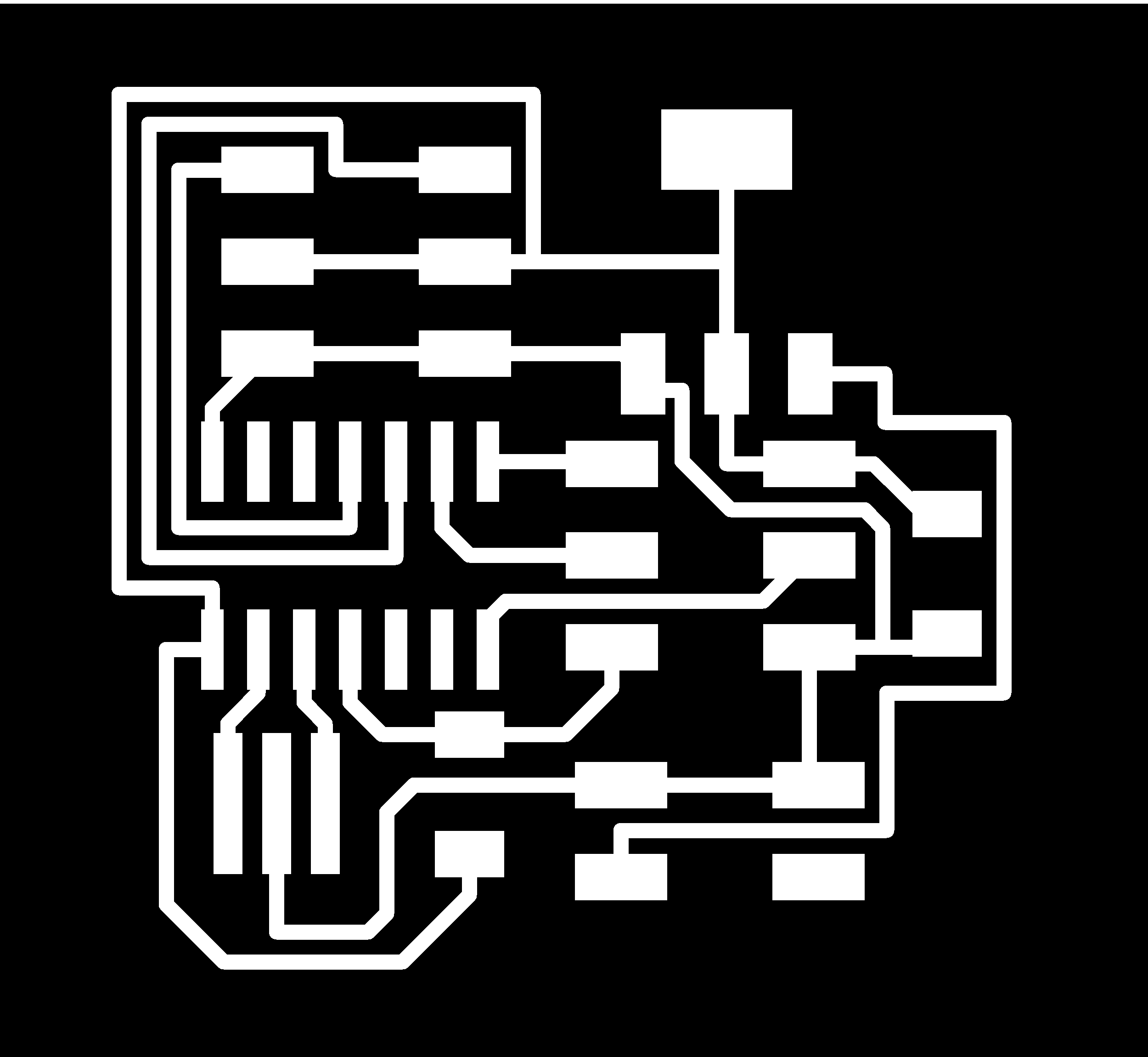
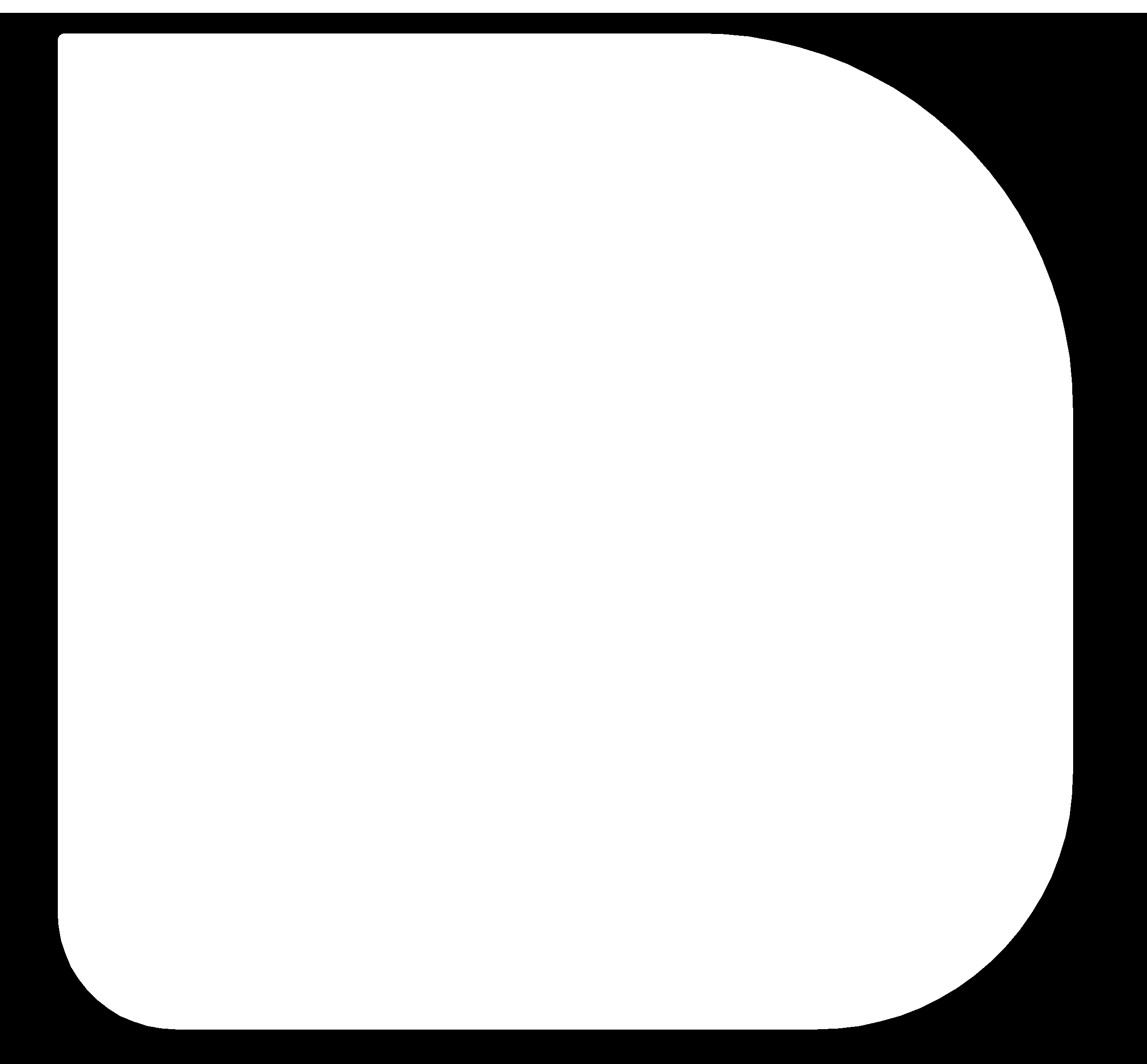
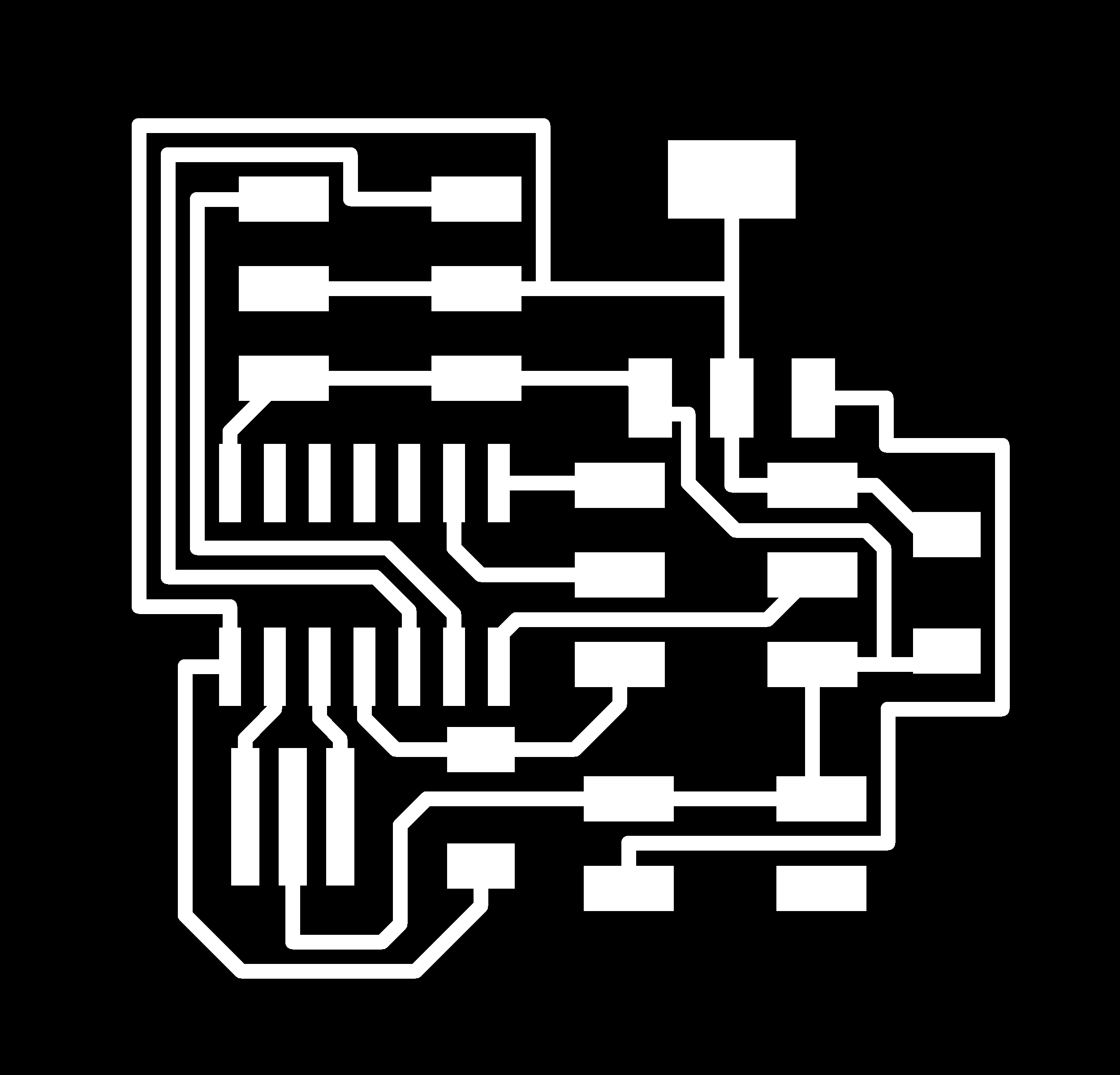
Then I prepared my images to mill my PCB. I Export them from Eagle as image with DPI 2000 and monochrome.
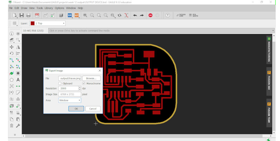
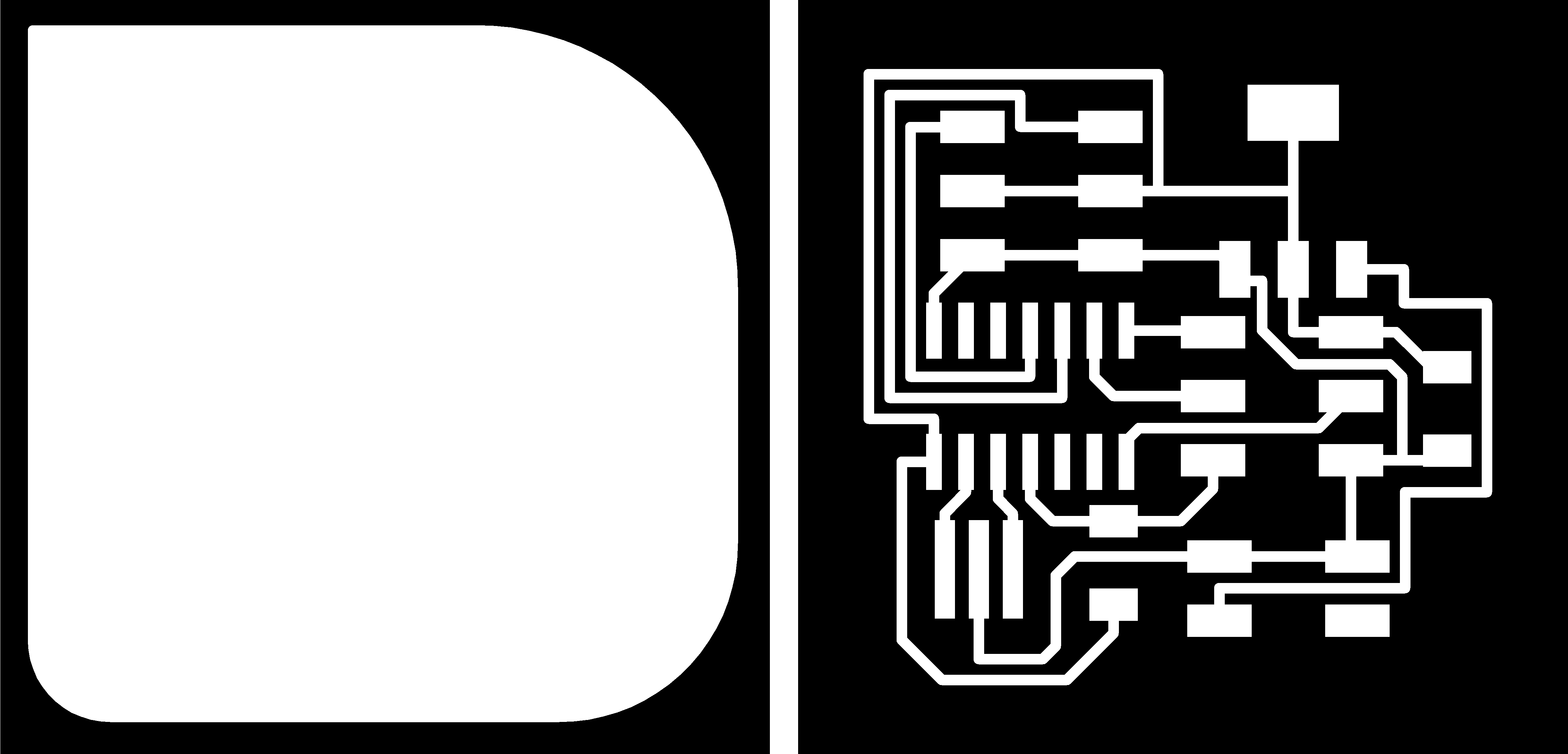
This is the result


Then I used GIMP Photo editor, to edit my images.
Fabricate my board
Then I prefer to make check with Fab Modules before I go to maker space … I made sure of all traces will mill as preview. Usually I use in the first process ‘traces check’ with offset value =1 to make sure all traces will be milled.
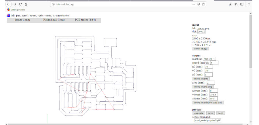
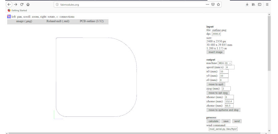
It looks perfect!
- So we now ready to change the value of offset to 4, and make calculate again.
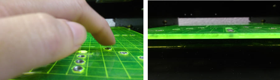
- I used the plate that we have been made before and our PCB fixed on it. So I just changed the plate.
- Fixed my endmill 1/64 carefully.
- Move the endmill to the right direction xyz.
- Now we can start!
Z Direction Error
I changed the plate of the machine with the plate we made from the previous weeks, and follow the steps of production PCB. I had a problem from the last week with the milling and Lamia also had this problem and we didn’t know why. The issue is, after set up the x,y,z position and the machine start milling, it just drew didn’t mill the copper! So we forced to increase the cut depth. I remembered I reached to 0.18 and Lamia reached to 0.25!
So this time I have the same issue and that very annoyed me because we made the same steps for every time … same plate ‘ new flat plate from Acrylic ‘, end mills and same PCB sheet but we didn’t know the reason.
I started as default setting in Fab Modules with cut depth 0.1 But the same here … then I canceled the process and move to xyzjog … then changed the cut depth to 0.15 … it didn’t work … So made it 0.2 … the same here … then I remembered the last value with Lamia is 0.25. So I tried it but didn’t work!
Servo Board_ Modela MDX 20_ Cut Depth from Nada Gamal on Vimeo.
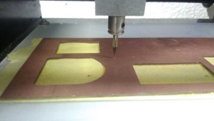
Finally, I reached to 0.28 cut depth!
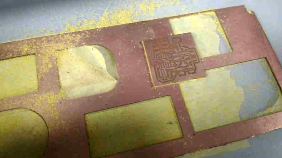
It looks well at first and when it reached to the middle, the end mill milled the copper layer and got through the second layer and the color of raytech was changed. At this stage I started to worry and was waiting for the moment when it would break! And many questions in my mind… Is should I cancel again? But I want to know the reason… So I continued watching carefully every movement and ready to press the VIEW key any moment.
Finally this is the result!
I love so much the moment when I wash the PCB. It makes me feel that electronics are friendly!
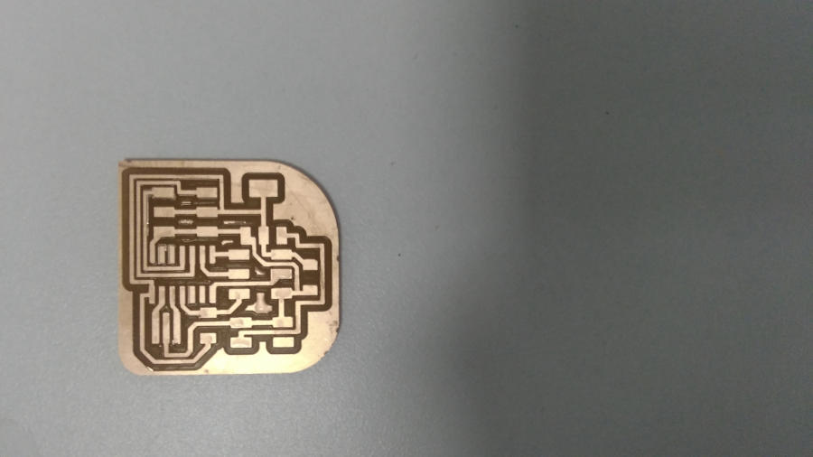
I noticed that the last two pads in Attiny44 is connected together and it will make a short circuit … So I used cutting tool to split the two traces.
I still thinking in the error that happened and try to get the reason. So, I remembered what happened in the electronics production week the same here because of the plate didn’t flat. But we made new plate from Acrylic and it completely flat. This is the only reason of the half PCB have cut depth and the other half have another one.
Then I remembered we fixed our plate on another Acrylic plate. Sure this is the reason!
So I reback to Mrehan documentation ‘Fab Academy 2018’, this is the strength point of the documentation that you have the history.
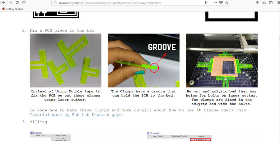
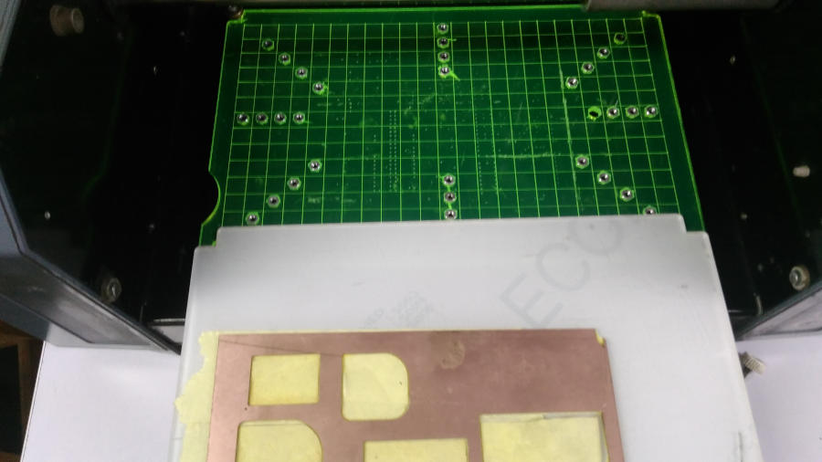
I really loved this design that Mrehan has been fabricated last year and the way of the fixation for the PCB as visualization wise, but when I tried it for two times … it makes errors if we didn’t clamp the screw well and the screws aren’t in the same Z direction.
 The photo doesn’t shown the friction that I’m talking about… but there is three srews in the plate didn’t fixed well. and it makes this result
I think that has been happened also with Mrehan at the electronics design assignment and she noted that.
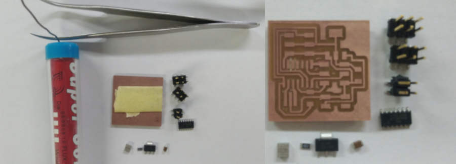
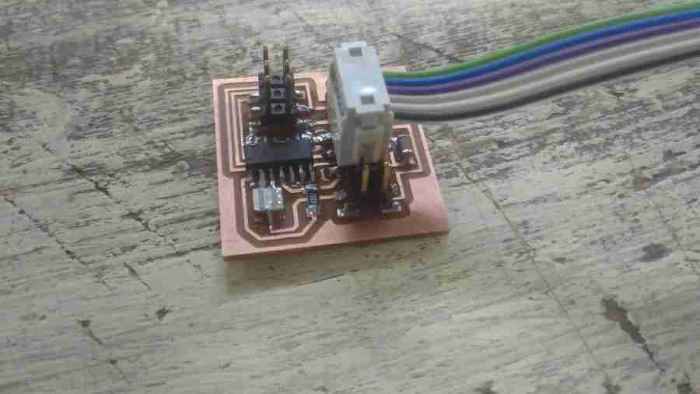
Weld the board
I started with attiny44 then the resonator, resistor and voltage regulator.
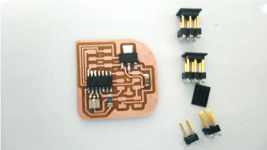
For this step … I noticed that I designed 2 pin headers with very closed to each other and I didn’t consider the distance between them was enough to connectors or not!
Great, It fit!
Redesign the servo board
I tried to prepare my board before our Instruct session to be ready, but through the lecture in motors Haggag explained Analog and PWM… voltage regulator… and talked many times about PWM… At this moment I started remember what I have been made!!
So I back to the above image, attiny44 and noticed that the servos pins that I connected with attiny44 is Analog PINs not PWM… So I need to redesign and fabricate my board.
I edited the servo PINs and connect them to PA7 and PB2 in the attiny44
Refabricate the board
Then I repeat the whole fabrication process and weld the board again!
Servo Board rev2 from Nada Gamal on Vimeo.
I usually fixed my PCB from the back with scotch tape in the table to be more easy in weld process.
Let’s Start!
Then, My fault here, that I started with the pin header!
The logic is weld the small components first. I usually made that, but this time I started opposite! :)
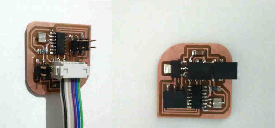
But it’s done anyway.
Finally, I tested it with the Avometer before program it, to make sure there is no short circuit.
Programming
For this step, finally we will start to program the board.
I used the make file that Neil uploaded in the lecture. To program my attiny44 with my USBISP that I made in week 05.
Then I need to upload the servo code to my board
We have two C codes in the lecture
The make file is the same in the two ways, software or hardware.
Then Kamel advise me to use software code because I connect another pins in attiny44, So the hardware code don’t match with my board. Because Neil used PA7 and PA6 PINs. And I used PA7 and PB2 PINs!
SO I used uploaded the software code and it works!
Download Files
Servo Board REV. 1
Servo Board REV. 2
C code
Neil’s Code for software C two-channel software PWM, Make file
After editing code to match my board C two-channel software PWM and used the same make file