8. Computer-Controlled Machining
Mode Board
Concept
I decided to make something big can reflect on my final project … I want to make a small scale façade. I’m interested more in the pattern … but to make it we need a strong structure for this pattern … mainly we use Aluminum boxes for the structure … but it isn’t acceptable to use a commercial part … we have to make our own … So I decided to make a structure for the facade with wood
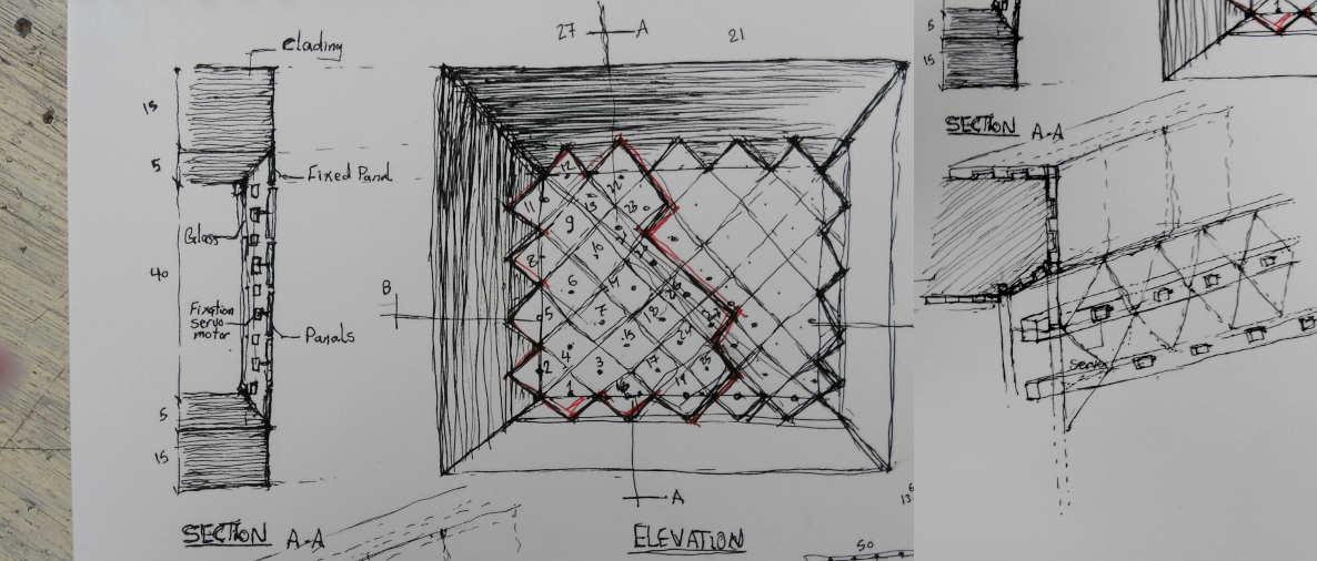
Freehand sketch
So my start from here
Design Process
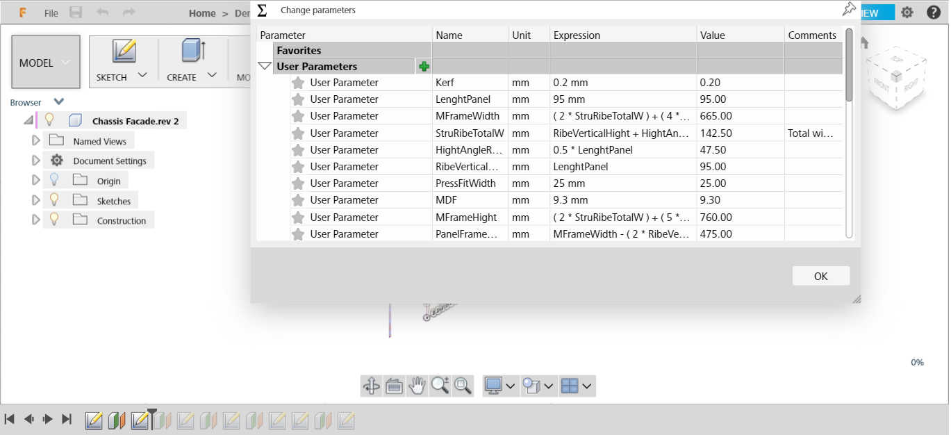
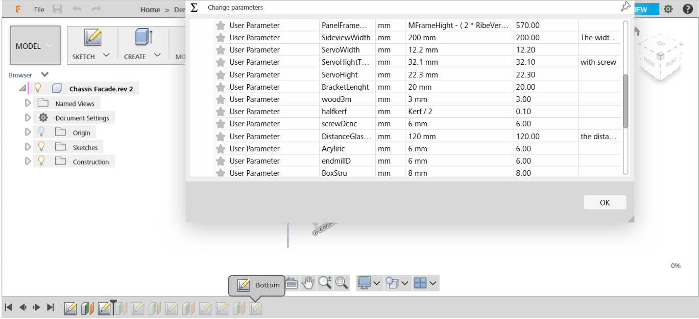
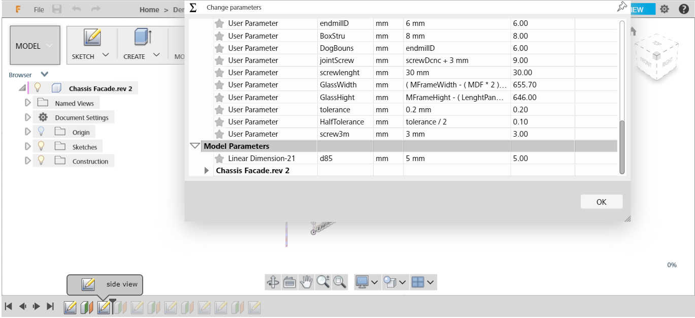
I used Fusion 360 this week to make my design. I usually start by setting the parameters that I can use.
- I supposed that will be a Kerf like a laser cutter machine, So I supposed that 0.2mm in my design till I will make a test.
- For the thickness of the wood, First I was confused if I will use MDF wood or counter wood. This is my first time using the CNC router and I don’t have a good experience of the different types of wood material. So We decided at the end to use the counter wood, we thought that it will be more strength than MDF. But the main issue for this type of wood, the counter contains multi-layers of Plywood. And we have a big issue with plywood in Egypt, we faced this issue before in laser cutter assignment… the same sheet with ‘500 mm * 300 mm * 3 mm’ have a different thickness from 2.8 mm to 3.9 mm. So when we reflect this issue in multi-layers of the same sheets, It’s supposed you imagine the result!
So I used 9.3 mm for the thickness of wood as a primary stage.
Dog Bones CNC Router Issue
I like this documentation about dog bones issue in CNC router, please check this link.
The issue when we want to make press-fit parts, we need to know the endmill path that takes to calculate the difference. The endmill takes a curved path in the corners. So if we design corner with 90 degrees, the original fabrication for this part wouldn’t be fit with another part. So we add a circle in the corner to make more wide space for another part to be fitted.
I found these lisp to draw the dog bones, but I didn’t try it yet. I preferred to draw it by myself in the first time to learn how can we design it and learn more from the errors!
lisp program for making dog bone CNC
Acknowledge to SSV Startup
Unfortunately, we have some issues with our CNC router in FabLab Egypt, So SSV startup for swimming vehicles, a startup in San3a Tech, the team is
Hussien Sorour, Mohamed Saleh, and Aly Magdy. They supported us to make our assignment.
Hussien explained to us the whole process from the design and export files until the generate code.
Mohamed learns us how can we use the machine from upload the generated code, fix the endmills, set the origin point x,y,z till start the cutting process. Also explained many scenarios if the machine makes error how can we work with that and if the electric is turned off, we can continue our process.
Fortunately, the more exciting part for me! during cutting processing, Hussien adds the Z safe homing with a value more than the machine default … So, during the whole process, everything is going well … after it finished the extruder moved to the Z safe homing that we added … Suddenly the machine stopped working!
For this moment Ali is fixed it, but Unfortunately, I didn’t know how he made that!
Technical Process
-
I backed to Fusion360 this week to make my design.
-
After finishing the design we need to export it with DXF format to the next software that we will use to generate the g-code. We used ArtCAM software, we took an old copy from Hussien, because this software doesn’t support from Autodesk right now.
-
Then we generate the code to Mach3 Software, that can send the g-code to the machine.
-
The dimensions of the machine that we used are 900 MM * 600 MM.
-
Fix our material well
-
Set the origin point X, Y, Z
-
Start process!
Before, I and Lamia started in the previous process … Hussien and Mohamed teach as a small workshop with this process in a sample that they have made before.
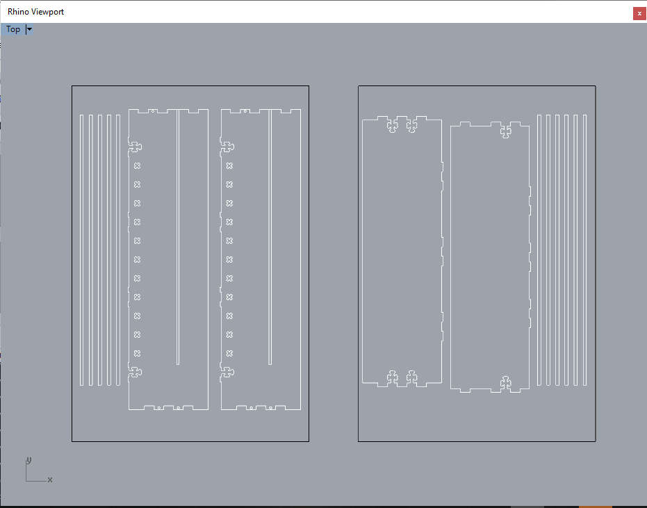
Then, we started to characterize the machine. For this stage I didn’t make the toolpath by myself, Hussien made that, I just draw small press-fit parts in Rhinoceros.
Test Tolerance
Before starting in the whole part, I want to make sure my press-fit parts will be good … So I started with all the small parts that could make errors.
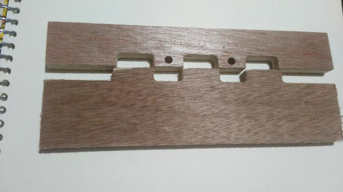
For this point, I made sure there is something wrong that I have been made in my design… It’s not a Tolerance issue … The press-fit very clear that the distance between female and male in one part doesn’t match with the second one!
For the second point, I decided to make the screw dimensions that match with the endmill 6mm to make all process with one endmill… And this decision is the most stupid one!
Then I back to my design to edit it … I started to make a tolerance test.
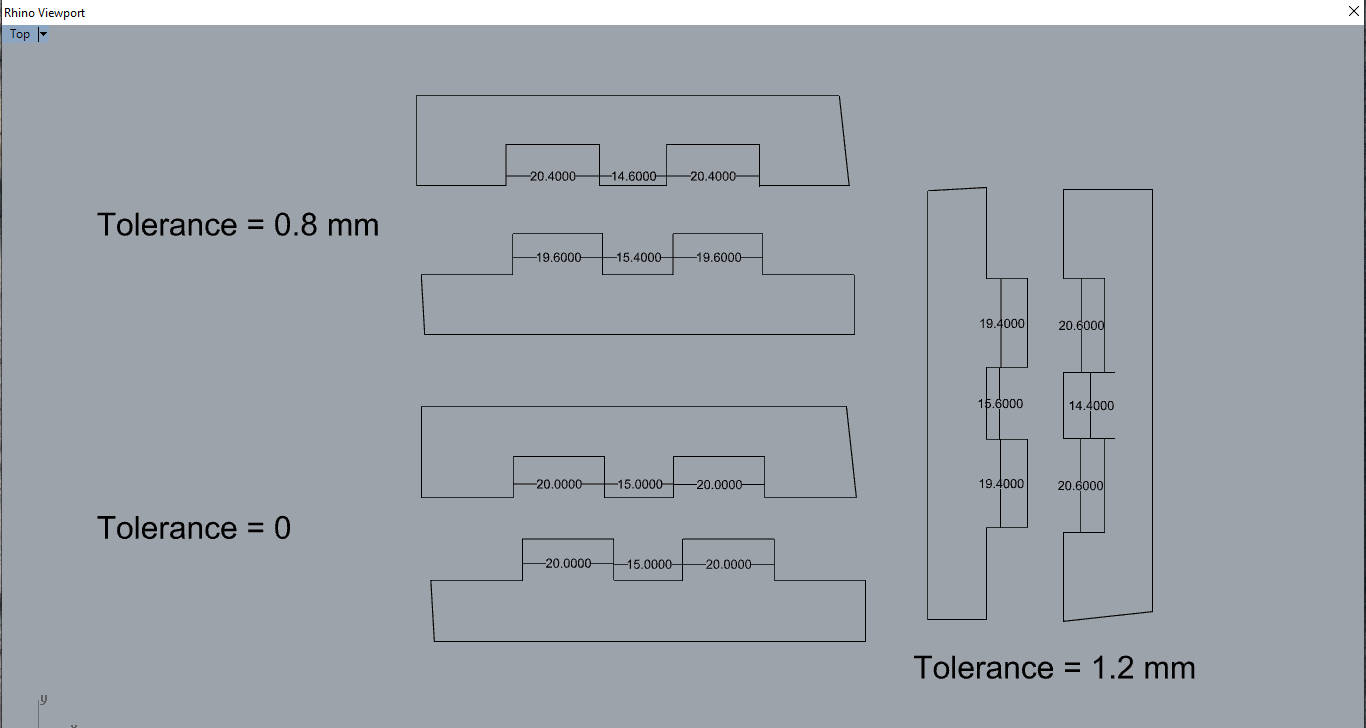
After this test, The zero-tolerance is good, if you make a press-fit joint and you used it a lot of times to split and collect it again … for the 0.8 tolerance is very wide for press-fit
After I measure the values with Caliper I decided to make a tolerance with 0.2mm in the female parts only … That means if I need a press-fit joint with dimension 15mm … the female part dimension will be 15.2 mm and the male part is 15mm.
Redesign
- Redesigned my parts again with the new tolerance
ArtCAM
For this stage, I started to prepare my G-code by ArtCAM, as we learned from Hussien.
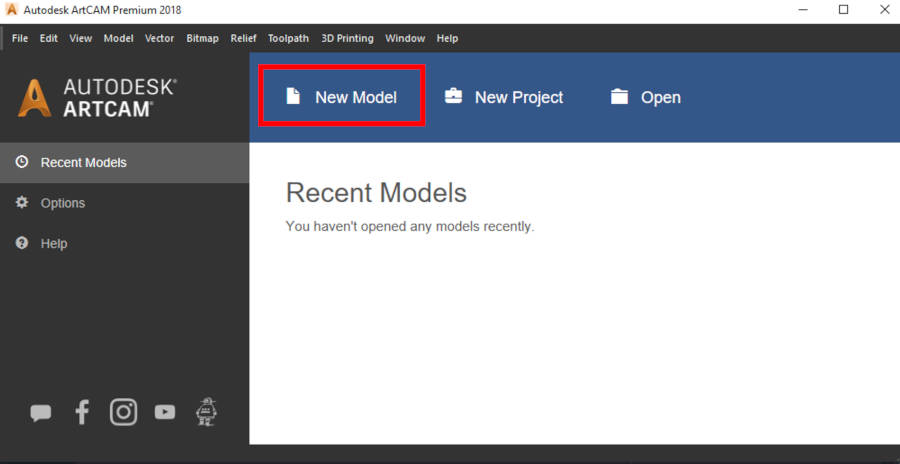
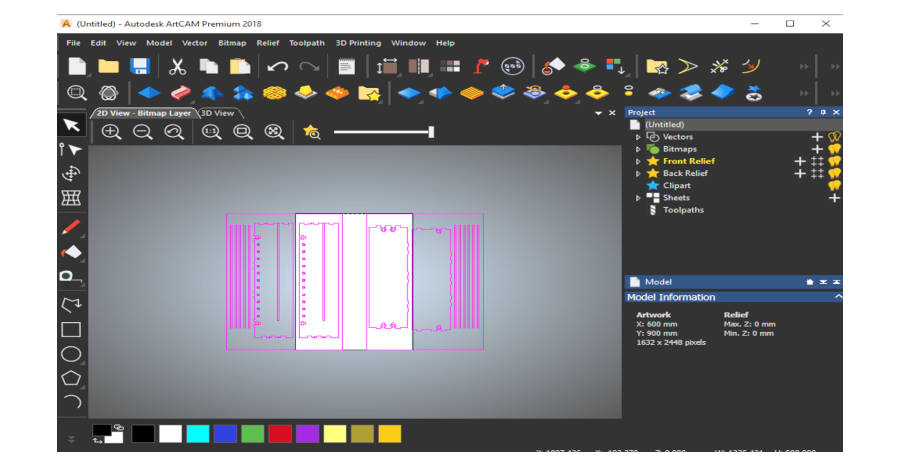
- Open ArtCam … Then select New Model
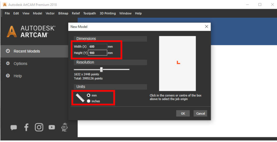
- Edit the dimensions as the machine that you used. Our machine dimensions are 900 mm * 600 mm.
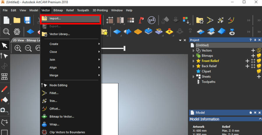
- Select Import from the vector tab.
-
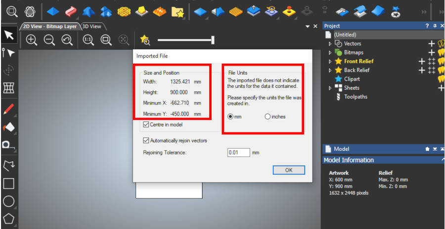
This message because I saved the two sheets in one file from Rhinoceros ‘I prefer this way than multi-files’, and I set my default dimensions in ArtCAM with one sheet. So the software informs me that there is a difference in the dimensions.
-
Press OKay.
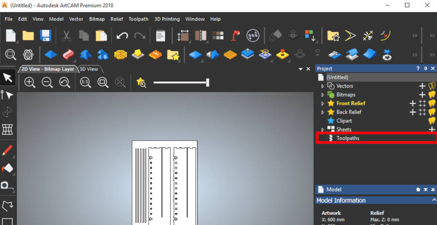
- Then, I select the second sheet I don’t need and delete it. Also, the rectangle around the sheet.
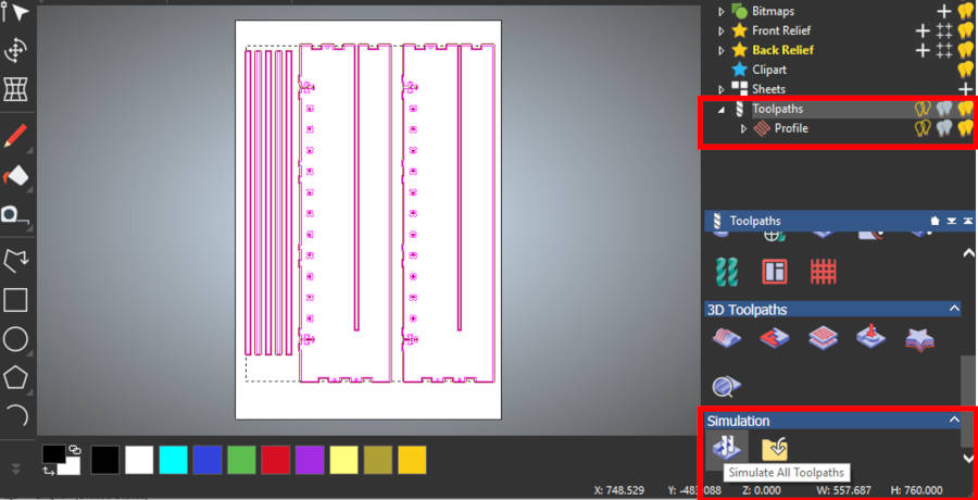
- Select the toolpaths.
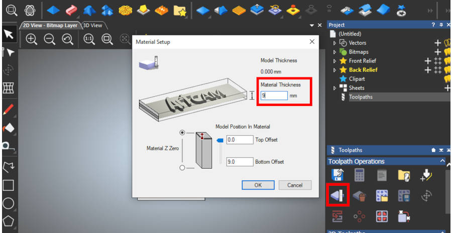
- Then, select the material setup.
- Edit the material thickness that you will use. In my case is 9 mm.
- Our machine, not the 5 axes … So the material position will be from top to bottom. So the top is 0 mm and the machine will start to engrave from top to bottom … In our case, we need to cut all the model from our sheet. So the bottom value will equal to the material thickness. But in case, we need just engrave, we will put this value less than the material thickness.
- Press okay.
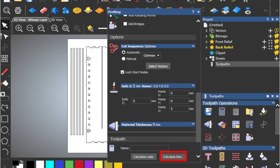
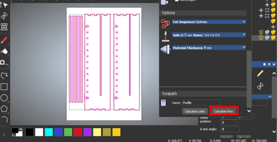
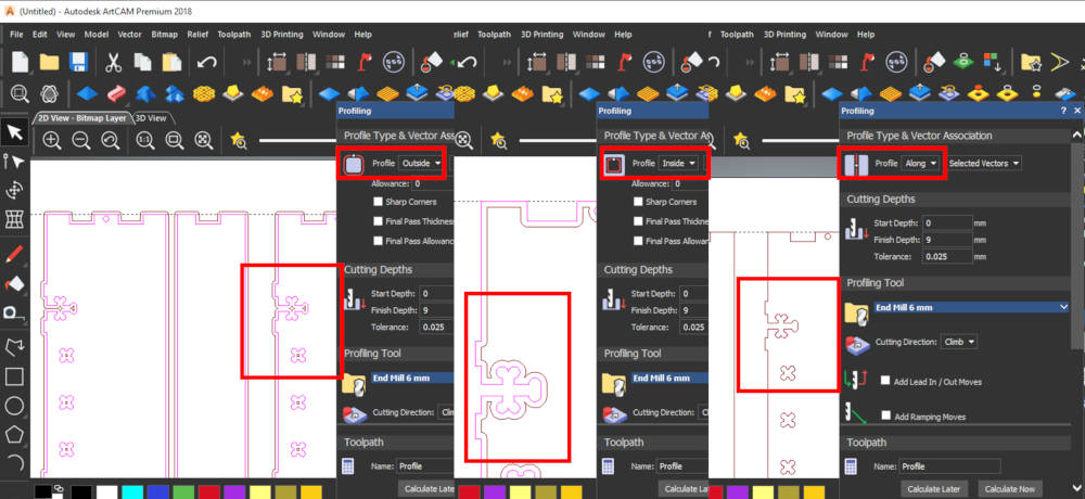
- Now, we need to make the profile.
- From toolpaths, select create profile.
- You can choose the profile from outside, inside, or along. The difference in the toolpath of the endmill will take. The profile will make offset to your drawing, with the thickness of the endmill. So, we have the option to chose the profile type that we need according to our drawing.
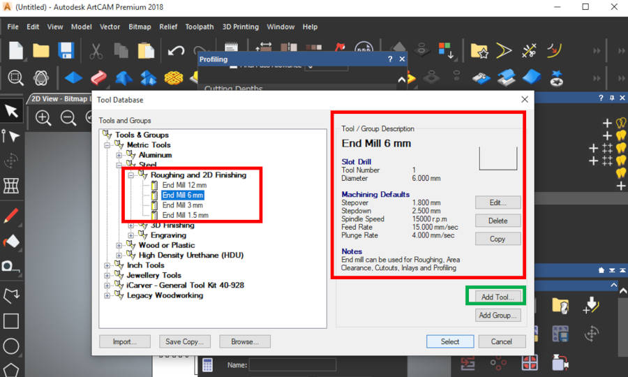
- Then, we need to select our tool ‘the endmill’.
References
- For the different types of endmills and collects… I recommend this website Precisebits, It explains the different types also according to the type of material.
- Also, this documentation, Introduction to Milling Tools, it’s very useful information.
- Also, we need to check in the Fab Inventory, about the endmill we will use.
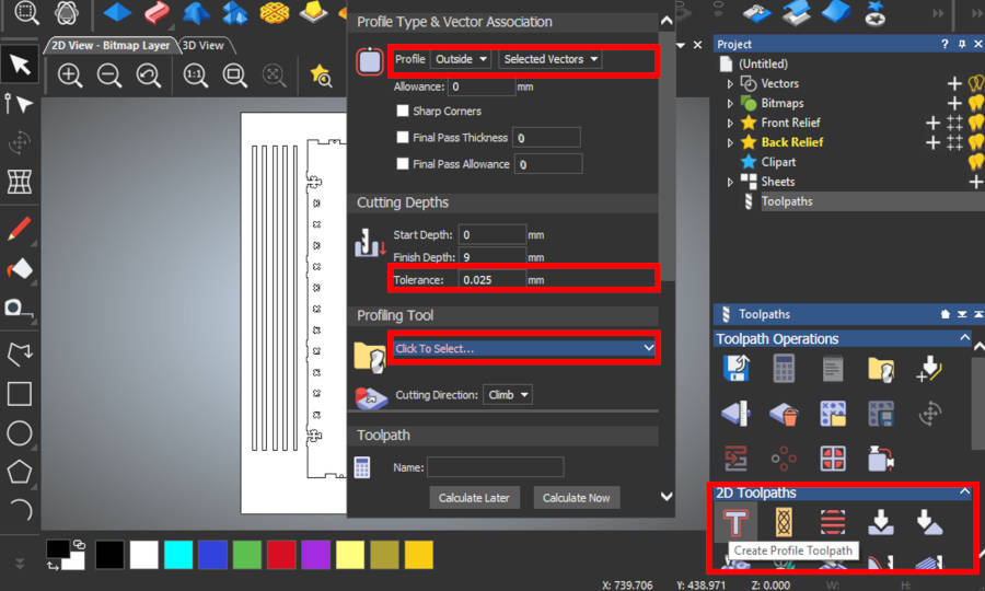
- After the tolerance test, we had made, I decided to use endmill 6mm in my sheet. So I just select endmill 6 mm. And all setting of the endmill just is uploaded.
- If the software doesn’t define endmill we need to use, Just select ‘Add Tool’ and add the setting of this tool from the datasheet.
- Press Okay.
- I changed the Feed Rate to 300 mm/s, according to the machine setting.
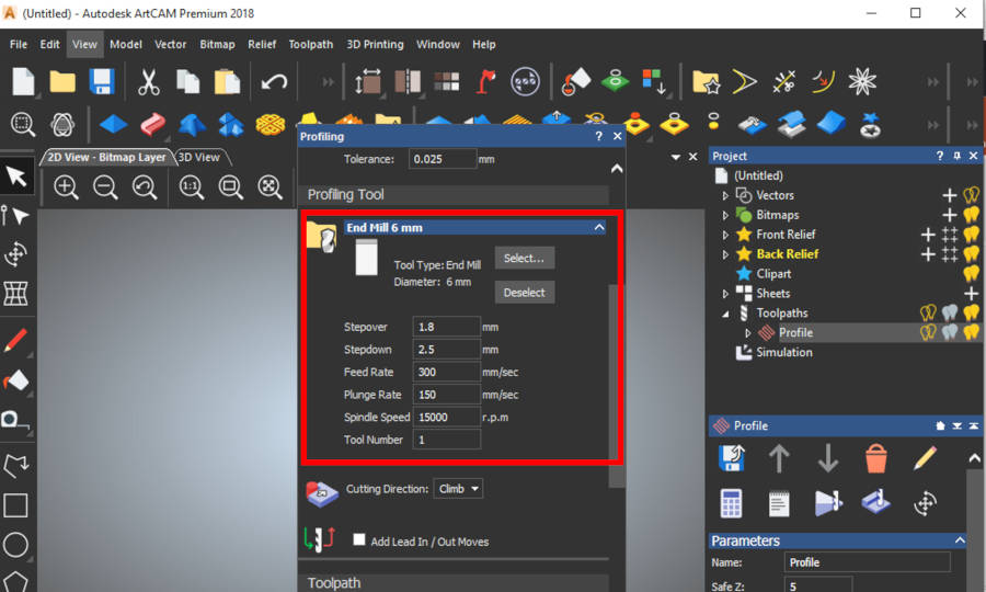
- Now, we finished the setting. We are ready to create profile.
- I got this message!!
- It means I have an error in my design, the object doesn’t close well! I am ashamed of this error because the architect shouldn’t have this error…
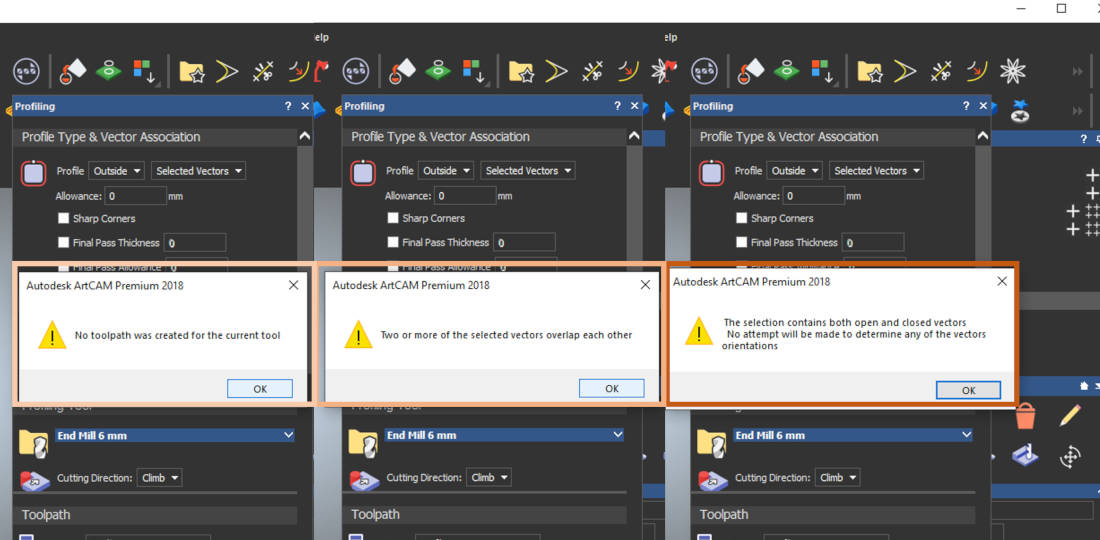
- I backed to my design in Rhinoceros… and draw a new polyline on the drawings.
- Then I made a little test to make sure of all lines is joined.
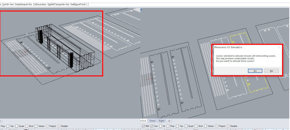
- I will explain the difference between closed polyline and open… we just need to make ‘Extrude Curve’…
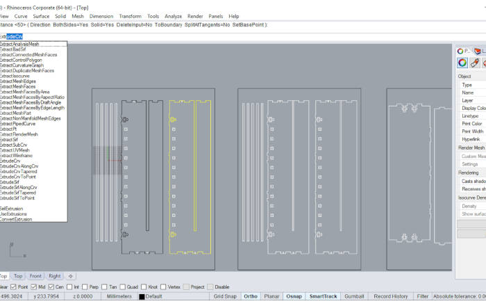
- In case closed polyline, the extrude will work smooth and will be sold if we select it sold… But in case the polyline is opened, we will receive this message… if we select yes, the extrude will be work but it’s possible to be a sold.
- So, this is a small test to make sure from our drawing before we export the file to DXF.
- Then, I repeated the whole previous process…
- After editing the lines, the create profile is working!
- We can make a simulation from toolpaths… to see the exact path the endmill will take in 3D.
- For this step, I noticed that there is an error here… the endmill can’t see this width…
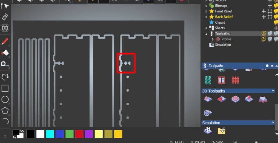
- So, I backed to the first option in the profile … Then I tried to compare between the three types of outside, inside or along…
- I preferred the Along option, I think it’s more realistic… So, I select Along and continue…
- For this stage we are finished… But in case we will use more than one endmill in the same sheet… we can make the previous steps and select only the layer or the object that we need to make this specific toolpath.
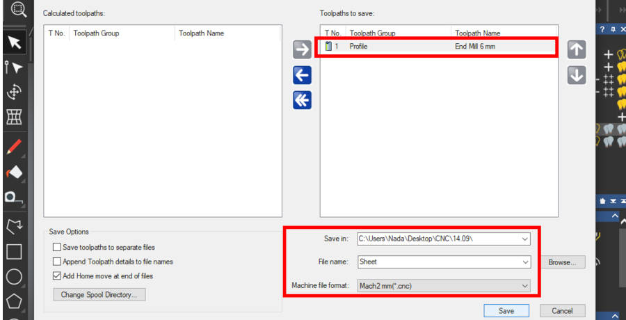
- For me, now I am ready to save the toolpath
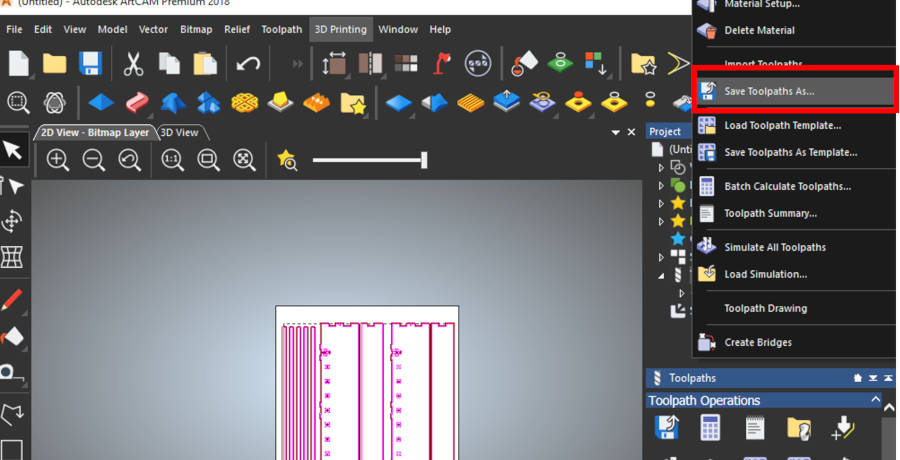
- Select the directory in your PC and the right format. Then Okay…
Make the previous steps with the second sheet.
March3 CNC
-
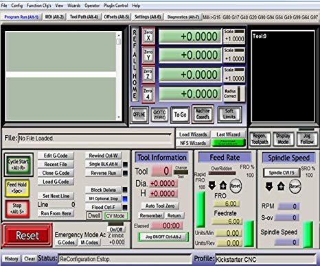
March3 CNC is the software that connected with the machine as I explained before.
-
Unfortunately, I don’t take images during this process, because this is my first time I used CNC router, So I was more interested to understand the process and focus in more details than take images…
-
So this image from google… First, we edit the X, Y, Z for the machine after we fixed the endmill and the sheet.
- For the Z position, it’s the same way as the Roland mill machine, we just need to touch the wood surface.
- Open the code.
- Then, Start…
- Watch your machine carefully and be ready anytime to press stop if there is anything is wrong.
Fabrication
- Make sure your sheet is fixed well
- Set your origin point ‘x,y,z’
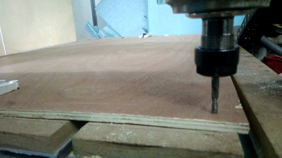
- Then Start process…
As the video show, the machine takes the path but in different Z position. That’s because we forgot to press set Z value after we edit it.
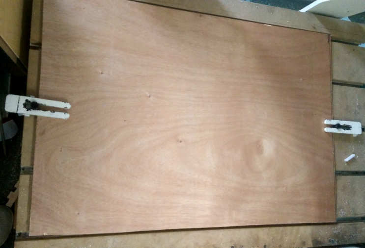
- My first part result!
It’s failed… it is different in z depth in one sheet in one part!
that means two things… is the z plate doesn’t flat… or the thickness of the material isn’t the same!
I have seen this scenario a lot of times with Roland mill machine, it’s familiar to me now…
- So, I don’t have a lot of sheets to lost it… So what I’m thinking now to reset the process with move the z-direction to down further and starting with the first line of code…
-
To reset the Z-direction and move the extruder down, we need to move out of the sheet first, then reset the Z direction then Start directly without back to x,y,z… because we will reset the z with negative value....
-
when we move the extruder in x,y direction .. the machine reached to the max in the x-direction and it seems that hit in the cheese, I didn’t feel good with that… but let’s continue…
-
After I edit my z-direction .. and everything is looking fine… I start the code from the first line… The machine changes its x,y position and started with a new point!…
-
So I defiantly lost my sheet!
-
So we start the process from the first again … to use the rest of the sheet we generate new code for the rest of the sheet … and continue the process
- This is my second part in another sheet. We decided to test the Z direction in the half of the sheet, to set the best result. Everything looks fine in the first, Then…
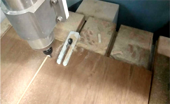
Now we missed the width of the sheet by this cutting we have made. So, now I limited with the width before and after this cutting. Also, we need to generate the code for the third time! to set the origin point with the new point in the sheet. So I decided to start with a new sheet and make sure the machine is working well then prepare the g-code to save time.
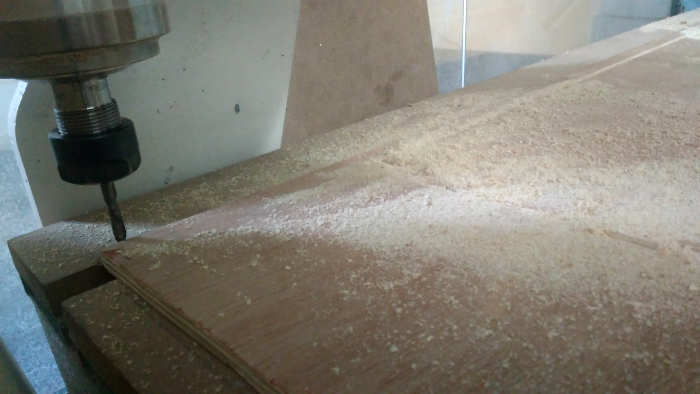
I started with a new sheet with the first g-code I have. But I have another issue … It’s the wood issue. It supposed that the endmill cut the wood in four stages, every time it moves down 2.5mm as the previous setting… But here in the video, the wood is cut in the first stage… and it’s very dangerous… the endmill will be broken at any moment… and the only way to solve this issue is to fix the sheet well from many points… It could be every 100 mm
This issue remembered me with Roland Mill Issue, but in Roland mill, we fixed the plate well with double face…
So at this time, I have no option to fix the sheet with this way!!!
Don’t do that… it’s very dangerous and it’s not true to do that…
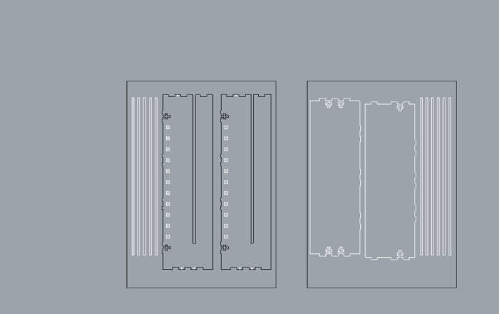
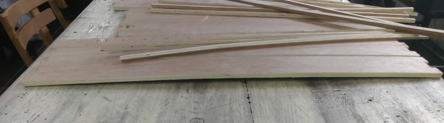
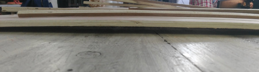
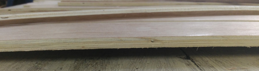
Final Product Parts
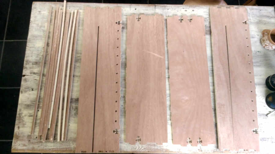
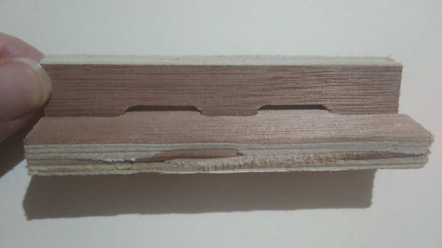
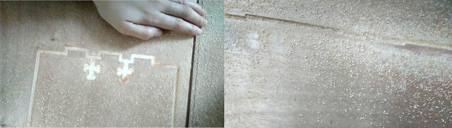
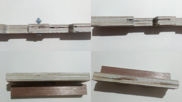
The Wood Issue Result
I thought these images are enough to explain why my press fit doesn’t look fine. I chose the counter wood because I thought that it’s better than MDF and could make a good result.
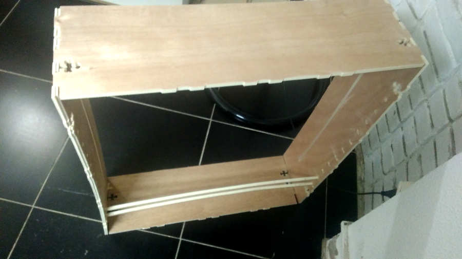
My Final Result
I don’t satisfied with this result. I faced a lot of errors during the whole process. I took a lot of wrong decisions. Sure I learned a lot, and this is the point of the assignment. This is my first time to test the CNC Router and made the whole process by myself with the guides of the SV team … Thanks to them so much.
I’m sure of that, the second time I will use this machine I will make my best!
Finally, I decided to use the Laser cutter machine for my final project fabrication… I don’t like the big scale… I think that the small scale with the small details will bring me the best result.