9. Embedded programming
Introduction
We have to do
- read a microcontroller data sheet
- program your board to do something,
- with as many different programming languages
- and programming environments as possible
This assignment based on the last electronics assignment that we have been made in the electronics design
The Microcontroller Data Sheet
It’s very interesting to me to read about the microcontroller and learn more in the third week of the electronics in this diploma!!
Actually, Haggag recommended an amazing book about AVR, The book name is Make AVR Programming. He read this book and the data sheet of the microcontroller in parallel during our instruct session. I learned a lot of worthy things.
I know what is the different between each AVR, and how can I back to each type. What is the structure of the AVR. The clock, fuses and the memory of the AVR. How can we configure any pin to be PWM or analog as we need.
So, now I have a great reference to back to.
Program My Great Board!
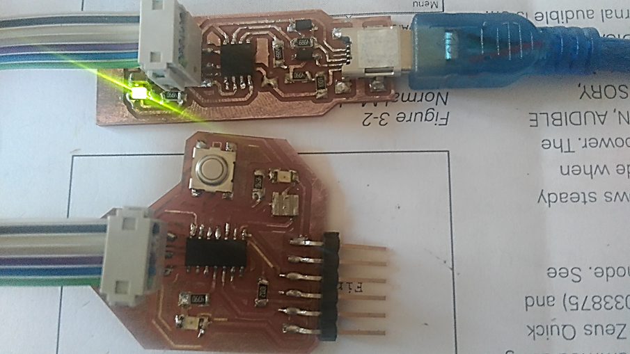
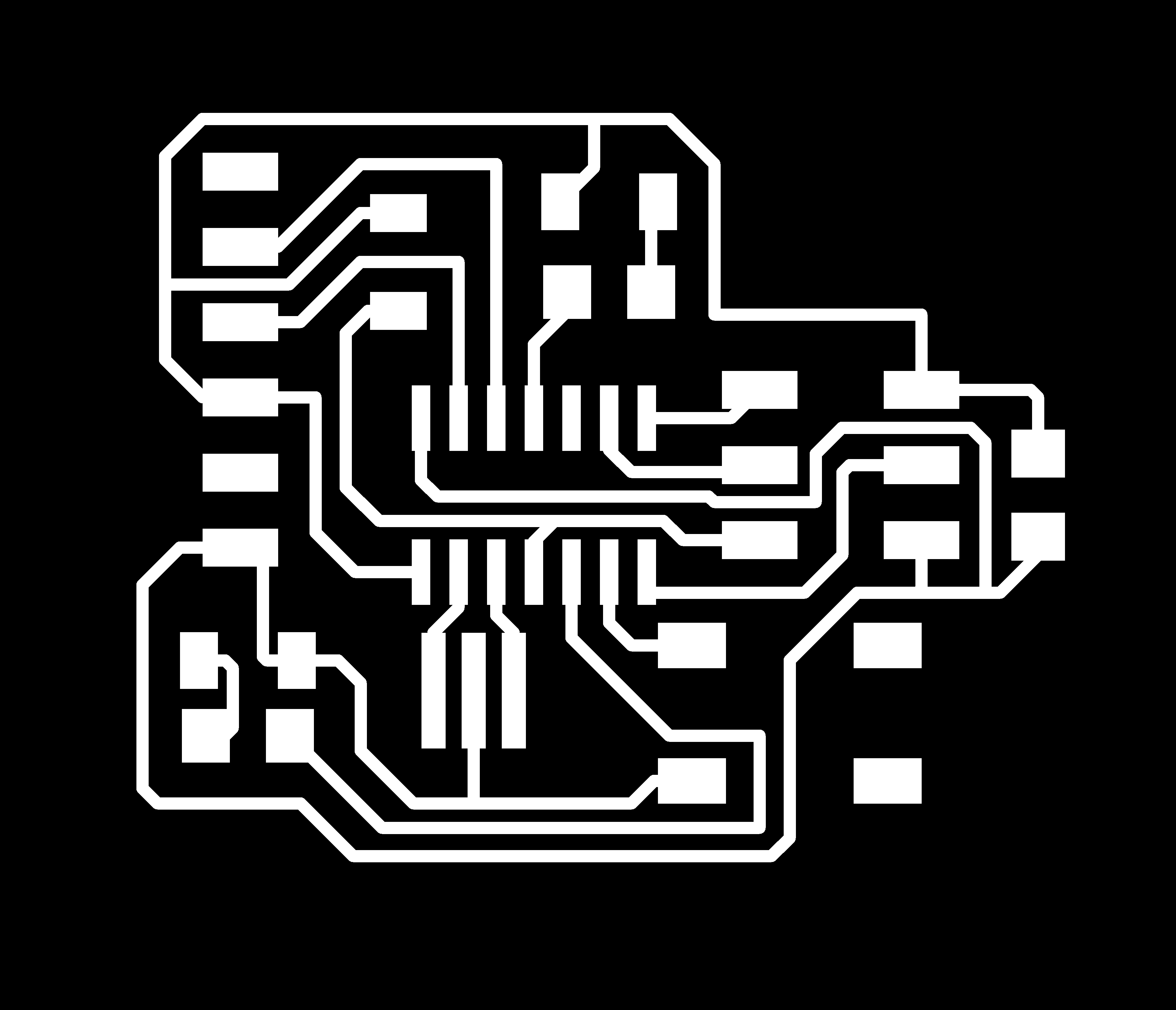
I started with my PCB that I have been fabricated in the electronics design
- We will use USBISP that we have been made in the first assignment of electronics, as a programmer to the board.
- I will use Arduino IDE as a programming language, So you can download software as per your operating system.
- Then we need to install the attiny in Arduino board manger, to be configured.
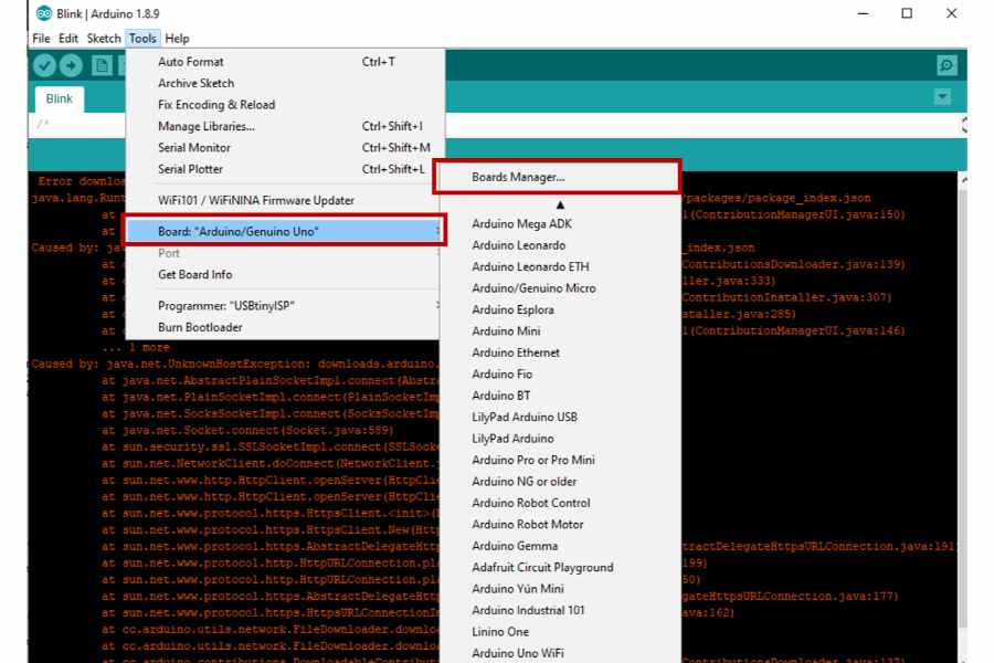
- Select from Tools >> Programmer USBISP, and the board attiny44.
- Open your code, then from Sketch >> upload using programmer.
Then it’s supposed that our LED is blink!
This is the whole process that we need to do.
So Lets start!
Install Attiny Board
Fortunately, I installed Arduino already. So the first step for me to install the attiny library. Lamia searched about it and gave me the link with all steps, So I followed these steps.
First, Open file >> Preferences
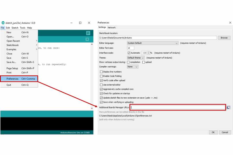
Then copy this link ‘https://raw.githubusercontent.com/damellis/attiny/ide-1.6.x-boards-manager/package_damellis_attiny_index.json‘in the additional boards manger urls
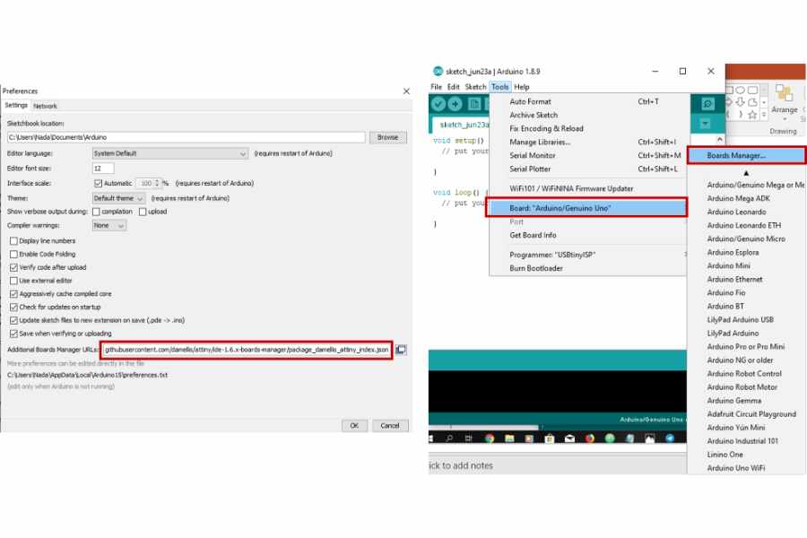
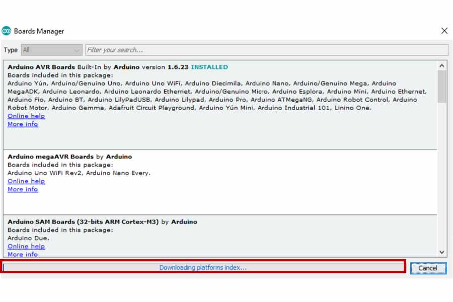
Then Open Tools >> Board >> Boards manager, It’s supposed that the library is direct downloaded.
For this step, everything is fine… till that error appeared with me!!
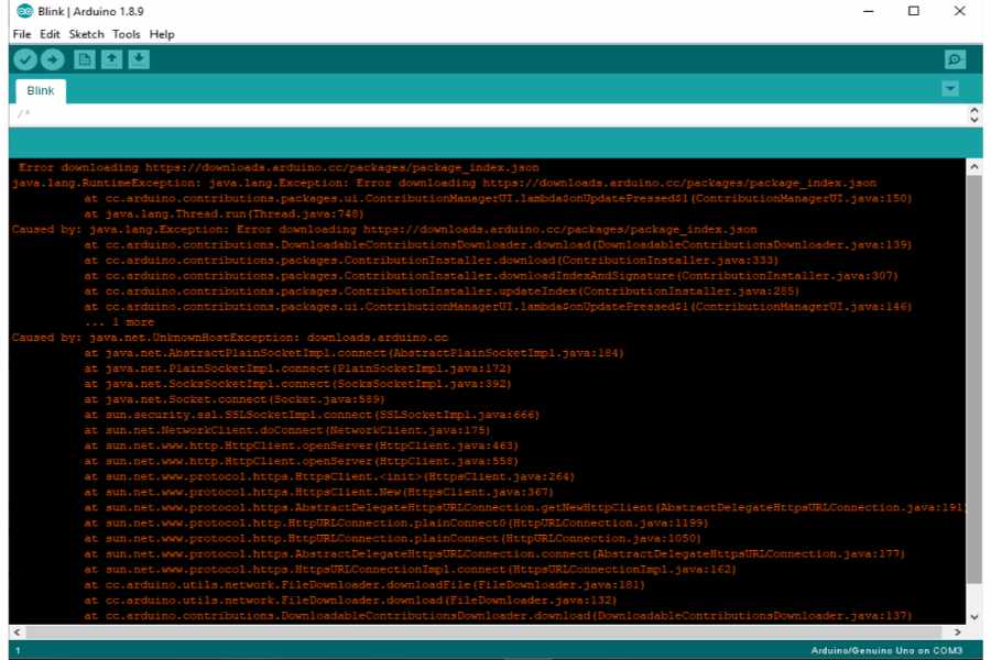
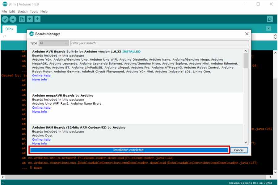
So I asked Lamia, She installed it before. Then she started to make the same previous steps! and I make sure I have been made the same steps but she wanted to continue
Then She just opened the boards manger, the installation completed!!
I didn’t wondered! that my PC makes a lot of things that make no sense!
So that’s fine
Now, the library of the Attiny is appeared, So just press install.
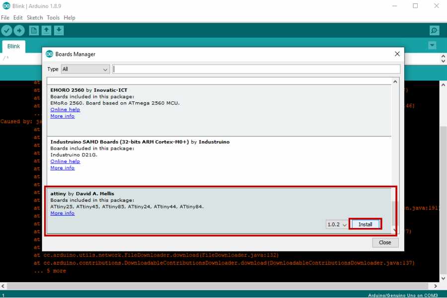
If we opened Tools >> Board >> the attiny is appeared.
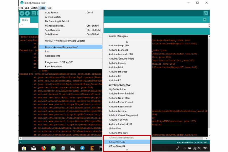
Congratulations!
We passed the first step!
Program Blink Code
To be honest, I started with the example in the Arduino library. I didn’t start from scratch. You can find a lot of codes in the library as shown. I used Blink code.
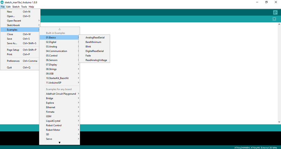
I want to make sure that my PCB is working good and didn’t burned yet! So I started with one LED.
Arduino Code
/*
  Blink

  Turns an LED on for one second, then off for one second, repeatedly.
  If you want to know what pin the on-board LED is connected to on your Arduino
  model, check the Technical Specs of your board at:
  https://www.arduino.cc/en/Main/Products

  modified 8 May 2014
  by Scott Fitzgerald
  modified 2 Sep 2016
  by Arturo Guadalupi
  modified 8 Sep 2016
  by Colby Newman
  modified 19 March 2019
  by Nada Abdelfattah

  This example code is in the public domain.

  http://www.arduino.cc/en/Tutorial/Blink
*/


void setup() {
  // initialize digital pin LED_BUILTIN as an output.

  pinMode(A2, OUTPUT);
}
void loop() {
  digitalWrite(A2, HIGH);
  delay(1000);
  digitalWrite(A2, LOW);
  delay(1000);
Fuses Issue
Then I noticed that the LED took about one minute or more to turn on. Unfortunately, I didn’t have a video for it! Then Kamel said that “That’s happens because we still used the inner crystal in the Attiny44, So we need to write in the Command prompt ” make fuse ” to set the external clock “Resonator”.
Then it works good with the delay … Then I tried variable values of delay, It’s more fun!
References
I found this link is very useful Also,this one Fuse Calculator
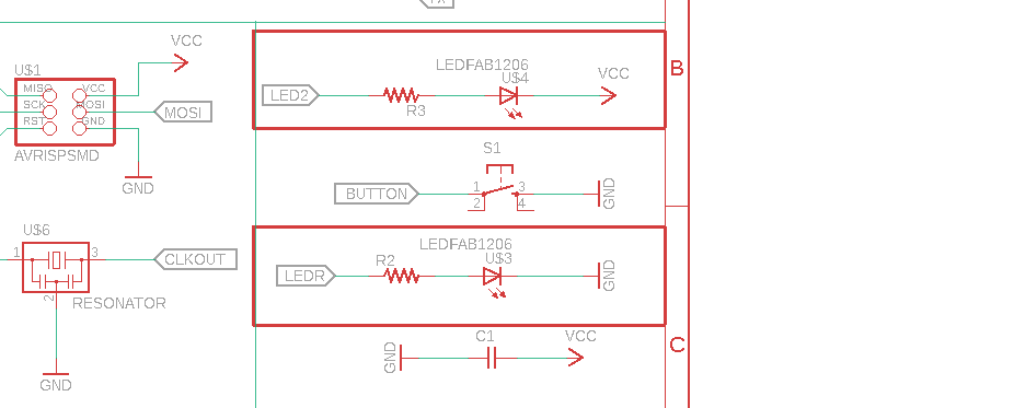
At this step I made sure of my PCB, So I excited to try the second LED and compare between two LEDs as per I connect one of them with VCC and the second with GND and we can opposite between LOW and HIGH by code to turn on and off.
Here I uploaded the code again to control in two LEDs as below
/*
  Blink

  Turns an LED on for one second, then off for one second, repeatedly.

  If you want to know what pin the on-board LED is connected to on your Arduino
  model, check the Technical Specs of your board at:
  https://www.arduino.cc/en/Main/Products

  modified 8 May 2014
  by Scott Fitzgerald
  modified 2 Sep 2016
  by Arturo Guadalupi
  modified 8 Sep 2016
  by Colby Newman
  modified 19 March 2019
  by Nada Abdelfattah

  This example code is in the public domain.

  http://www.arduino.cc/en/Tutorial/Blink
*/
void setup() {
  pinMode(A2, OUTPUT);
}
void loop() {
  digitalWrite(A2, HIGH);
  digitalWrite(8, HIGH);
  delay(10);
  digitalWrite(A2, LOW);
  digitalWrite(8,LOW);
  delay(10);
After that we discovered that the second LED don’t respond. So Kamel’s comment in the location of the resonator is far away from its pins … so it could be the reason. By try and error a lot of times … We write in the command prompt by fault … make program!!
Make Program for my board by USBISP … So during the programming I disconnected the usb before complete the programming.
I thought that the attiny44 is burned because I programmed it with the make file to USBISP
So, I have to repeat my PCB!!!
So I added the second LED in the code as below, We have to make sure of the number of Pin in the Attiny44 which equal in the Arduino PINs. Actually I prefer to review any component from this view, It shows every PIN, Just google it.
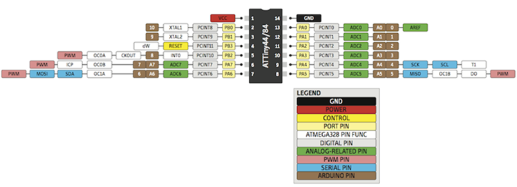
So second LED here connected in PB2 in attiny44 that opposite PIN 8 in Arduino.
/*
  Blink

  Turns an LED on for one second, then off for one second, repeatedly.

  If you want to know what pin the on-board LED is connected to on your Arduino
  model, check the Technical Specs of your board at:
  https://www.arduino.cc/en/Main/Products

  modified 8 May 2014
  by Scott Fitzgerald
  modified 2 Sep 2016
  by Arturo Guadalupi
  modified 8 Sep 2016
  by Colby Newman
  modified 19 March 2019
  by Nada Abdelfattah

  This example code is in the public domain.

  http://www.arduino.cc/en/Tutorial/Blink
*/
void setup() {
  pinMode(A2, OUTPUT);
  pinMode(8, OUTPUT);
}
void loop() {
  digitalWrite(A2, HIGH);
  digitalWrite(8, HIGH);
  delay(10);
  digitalWrite(A2, LOW);
  digitalWrite(8,LOW);
  delay(10);
and this is the result of this code
Blink LED _Microcontroller attiny 44 from Nada Gamal on Vimeo.