Week 4 - Electronics Production

This week's tasks are:
- Characterize the apecifications of PCB production process ( group assignment).
- Make Fab ISP in circuit programmer using milling machine.
- Program the circuit to be able to use it in next weeks.
Step1: Getting introduced to some concepts
- In System Programming (ISP): the ability of some programmable logic devices, microcontrollers, and other embedded devices to be programmed while installed in a complete system, rather than requiring the chip to be programmed prior to installing it into the system.The board ISP programmers have the abitlity to pass the code through it to another board.
- FAB ISP:An in-system programmer for AVR microcontrollers that we will use to program the microcontrollers on other boards we make.
- Bootloader: The bootloader is the starting program that runs the microcontroller when it's powered. It figures out if there is a new code trying to be programmed on the microcontroller, so it puts the program code on the memory and start it. Or no new code it trying to be programmed ,so it gets the latest program on the memory and run it.
Step2: Characterizing the Machine
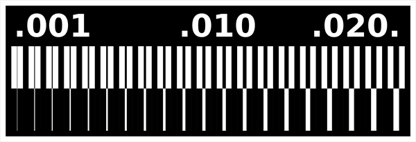
As a group assignment I decided to make a resolution test to know the precision of 0.4 mm v-Curve milling bit.

Traces Image
Outline image
we downloaded traces image and outline image. The reason we need two images with this exact colors and the milling and cuttong process are explained in the FAB ISP section below.

The result we got is wonderful and the 0.4mm v-curve milling bit is very precise and can capture almost all the details.
Step3:FAB ISP milling & Cutting
- Get the needed files
- Fix a PCB piece to the bed
- Milling
- Cutting
I dowloaded the PCB files from the electronics production schedule page. I chose to make the board that has a resonator.
The software we use (Fab Modules) Needs two PNG files to get any PCB done
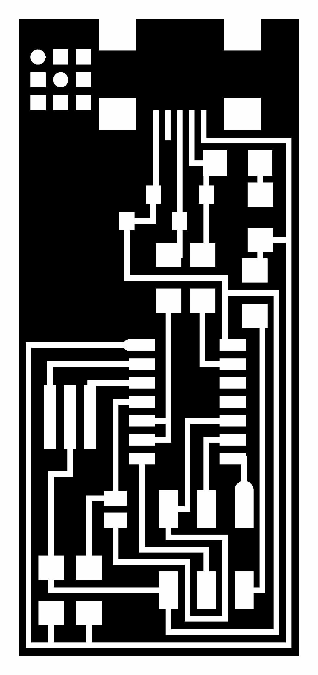
Because a milling bit is used for milling the PCB and another drilling bit is used for the cutting and drilling we need two differnt files.
PNG file with traces in white and background in black.the machine will mill all the black area and leave the white.
PNG file with outline and holes(if the board has through hole components) in black and background in white.The machine will remove cut and drill the black area and leave the white which will contain the milled traces.

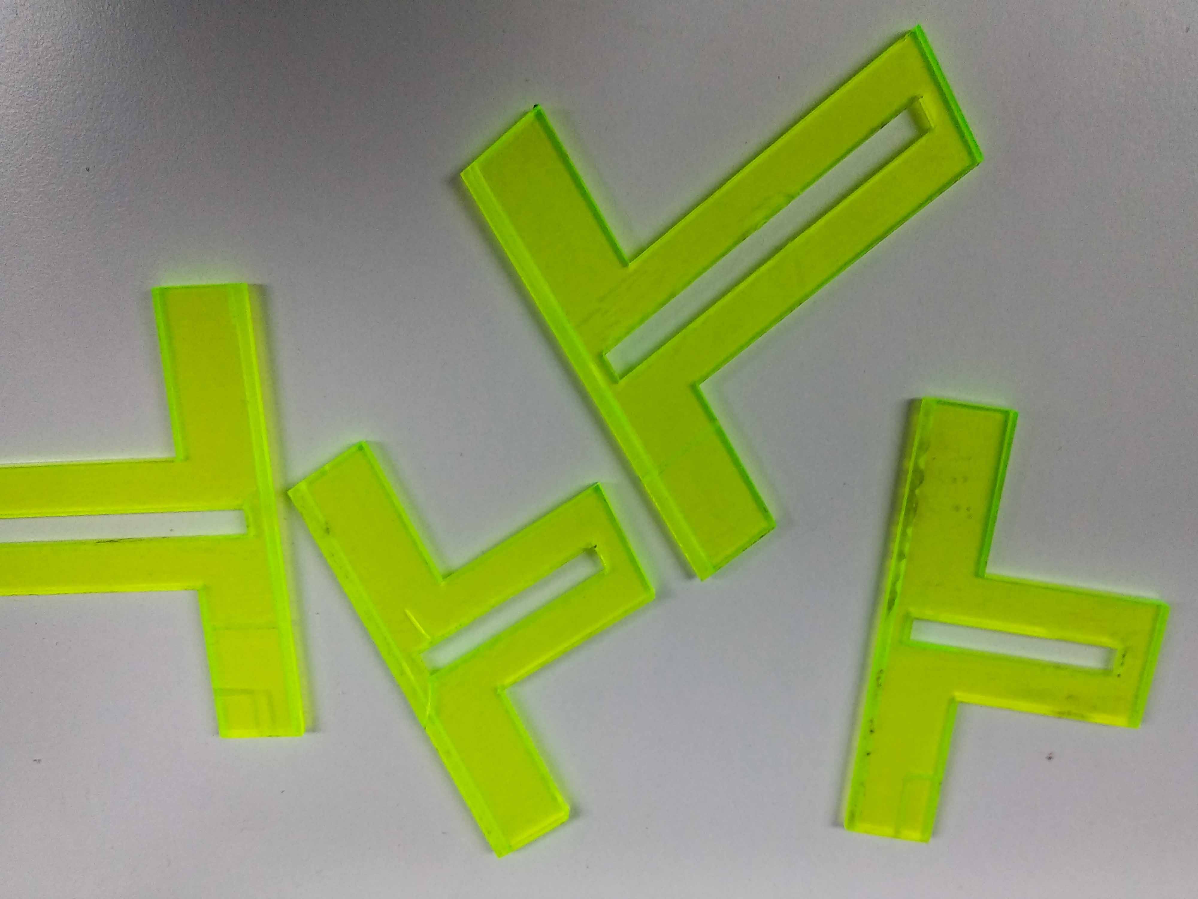
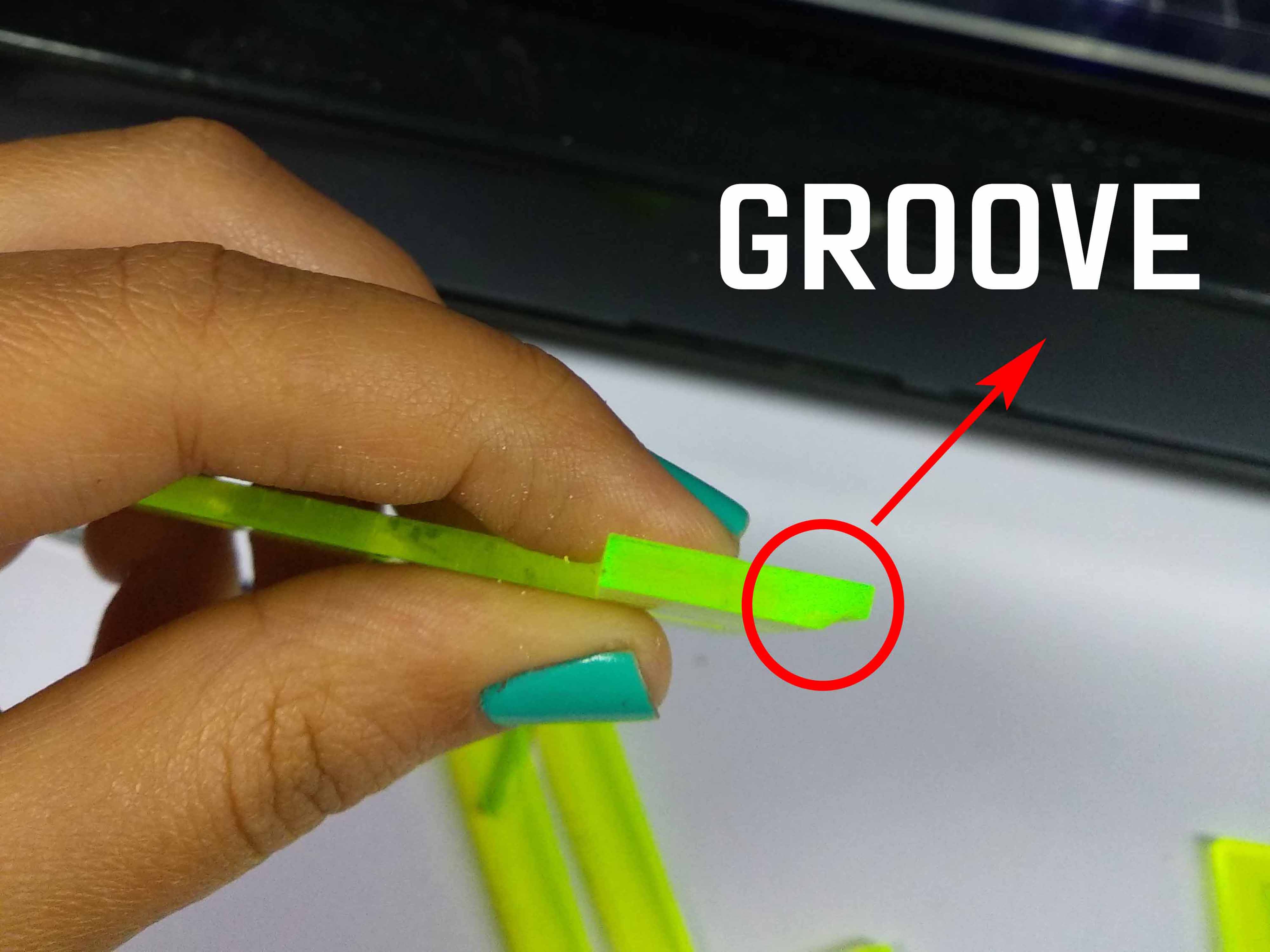
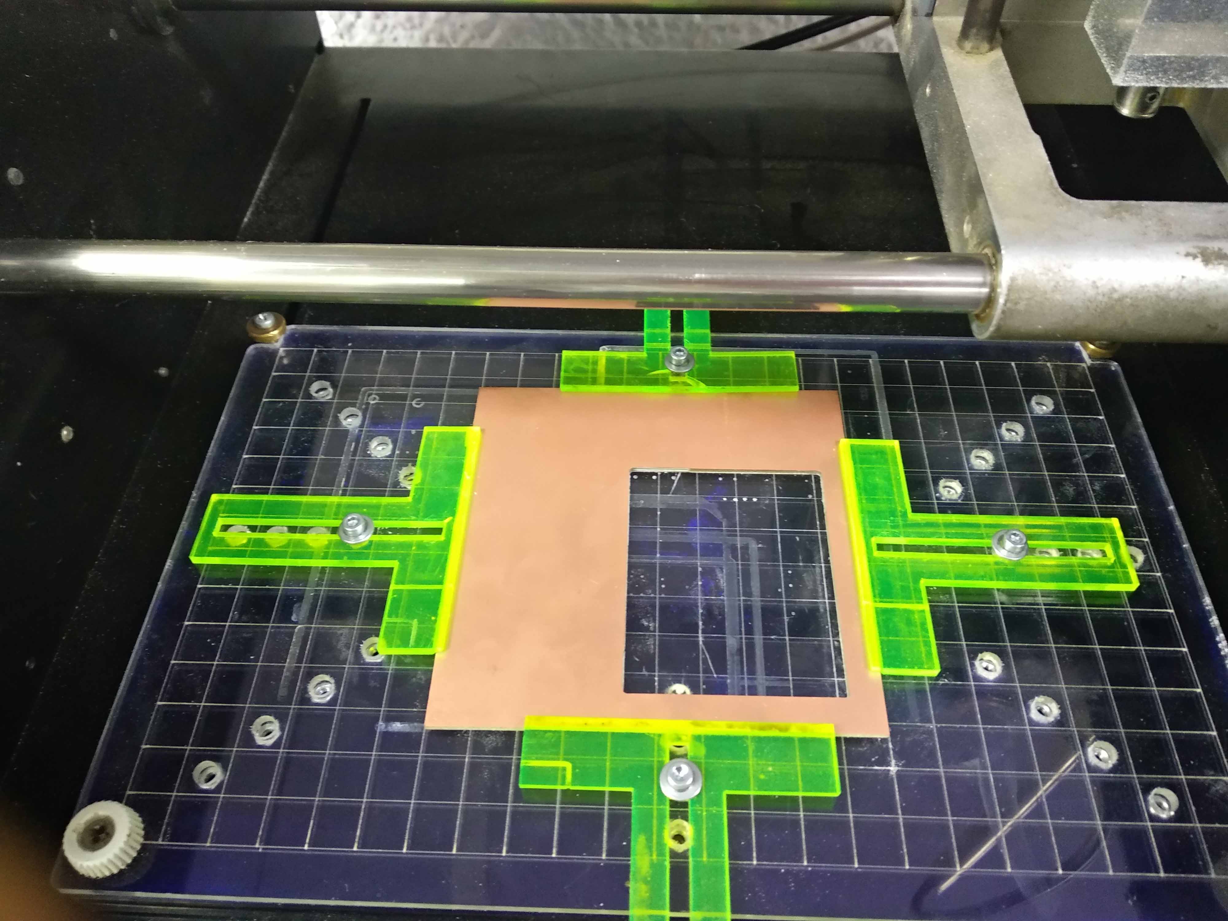
Instead of Using Double tape to fix the PCB we cut those clamps using laser cutter.
The Clamps have a groove that can hold the PCB to the bed.
We cut and aclyric bed that has holes for bolts on laser cutter. The clamps are fixed in the aclyric bed with the Bolts.
To know how to make these clamps and more details about how to use it please check this Tutorial made by Fab Lab Dhahran guys.
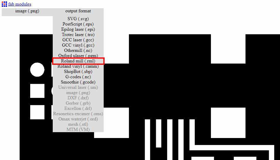
I chose the output format to be roland .rml file.
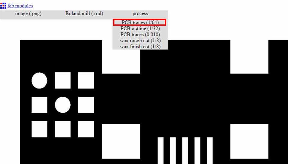
I chose the milling process which is PCB traces
Select the machine ( MDX-20) and the speed to 4 mm /sec
I choose the cut depth to be 0.1 mm which is the thickness of the removed copper, Tool diameter 0.4 mm and the offset to (-1) to remove all uncessary copper and make it more easy to solder.
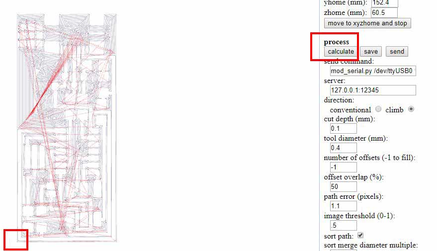
I presses calculate then the machine movement shown. I saw the x,y lines at the left bottom so I figured out that this is the start position.
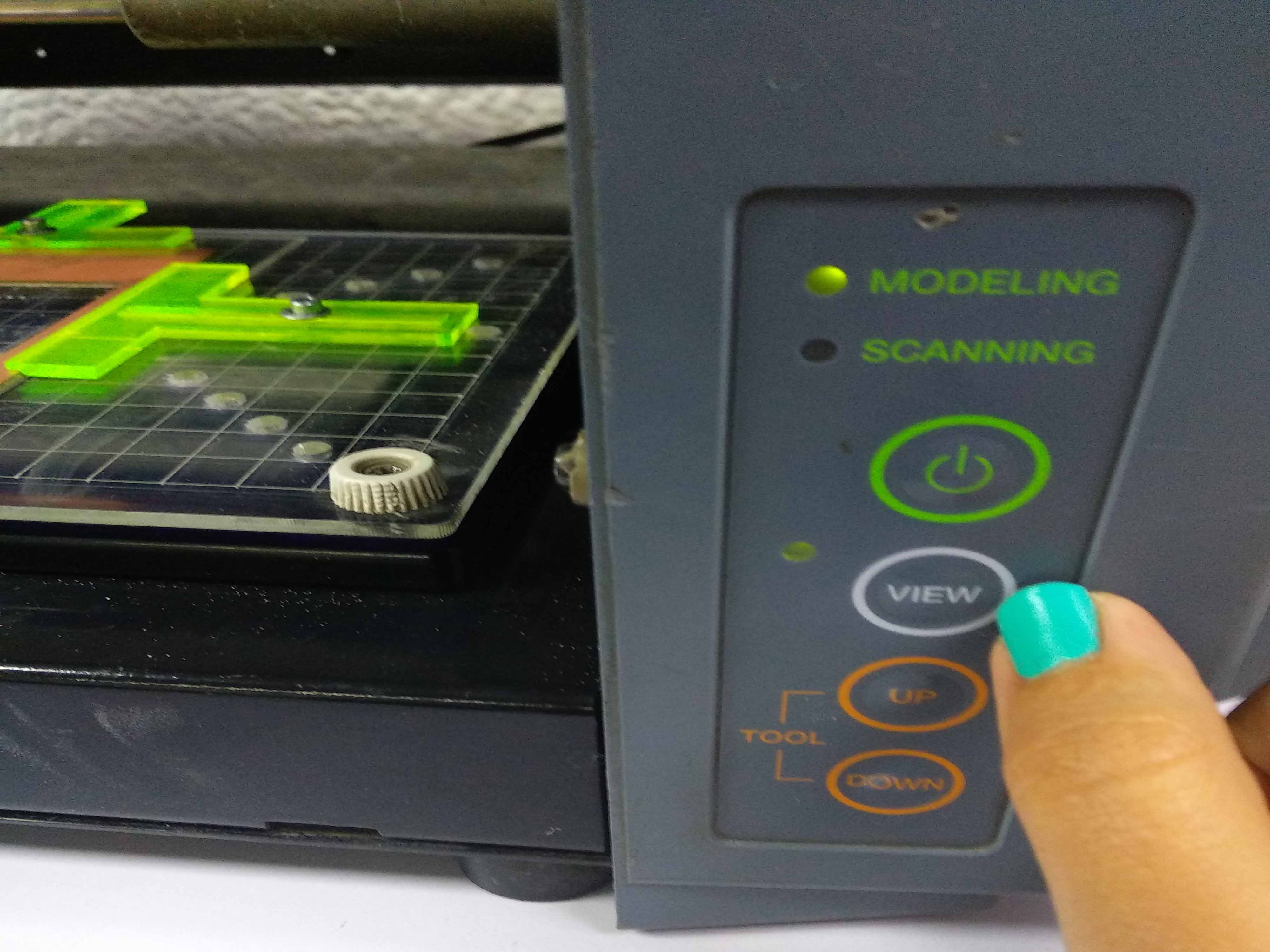
I pressed the view mode because the machine doen't accept any orders from the software till the view mode is on.
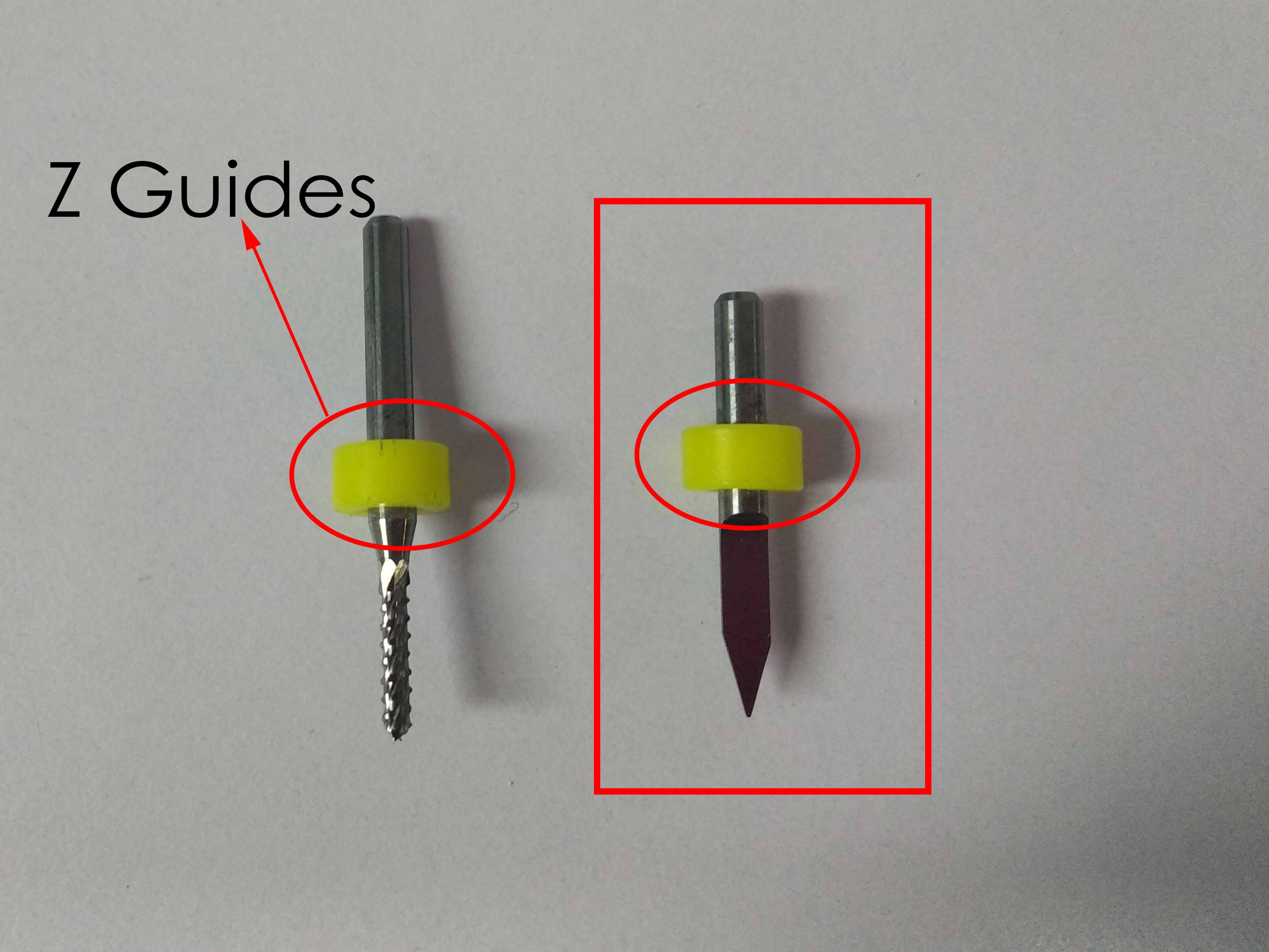
The milling bit I'm going to use is 0.4mm v-curve milling bit.The yellow parts are Z guides.
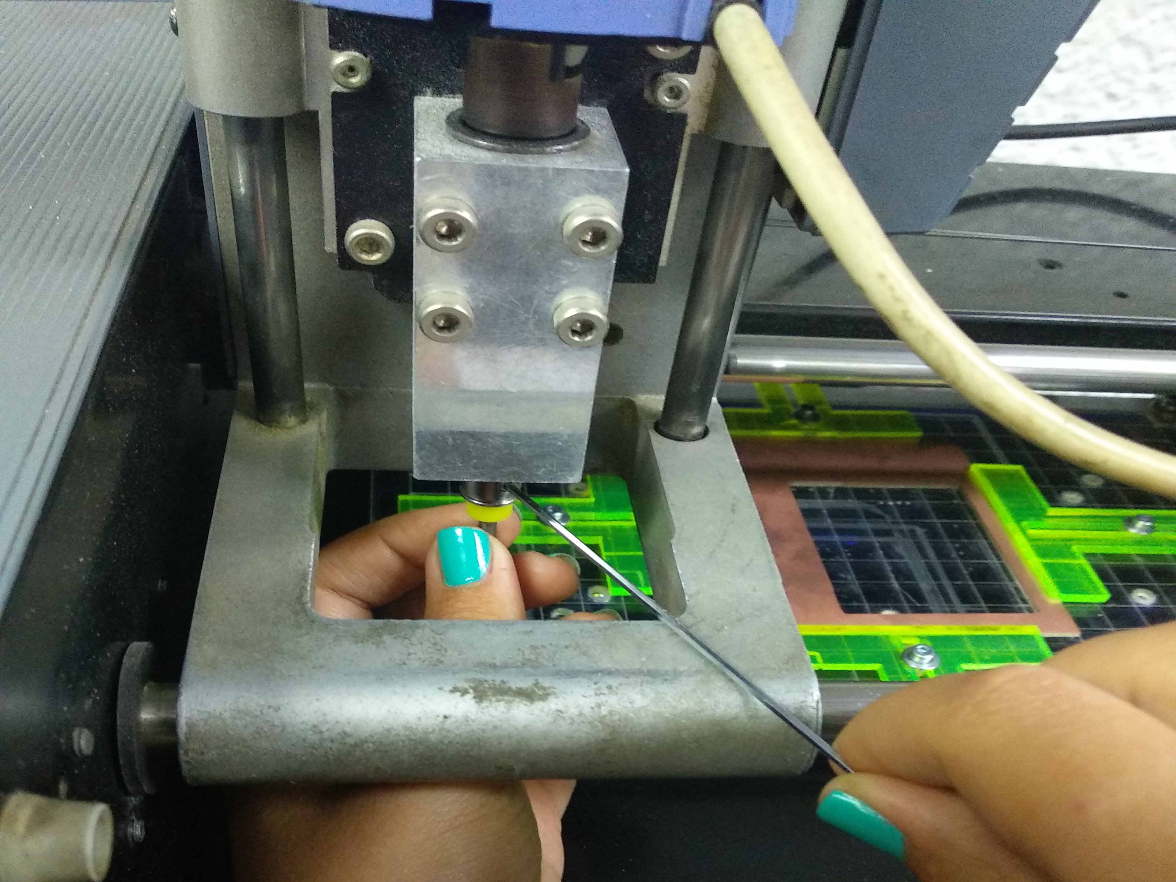
The Z gides are fixed at the same height for all the bits to make it easy to change the bith and don't have to adjusr the Z level again between processes. I attached the bit to the colt till it touched the yellow part.
Move XYZ0 to a start position where there will be sufficent area for the PCB.
Move the Z from the machine down bottom till it touches the PCB then Press send on the software
The machine will start milling.
For Cutting I followed the same steps, Imported the outline photo, chose roland mill output and chose the process of PCB outline
I chose the MDX-20 machine type and wrote the same x0,y0 position then made the tool diameter to 2mm as I'm using a cutting bit of 2mm diamter.
I made the stock thickness to 1.1 mm and these values depends on the bit used.I didn't change any other parameters.
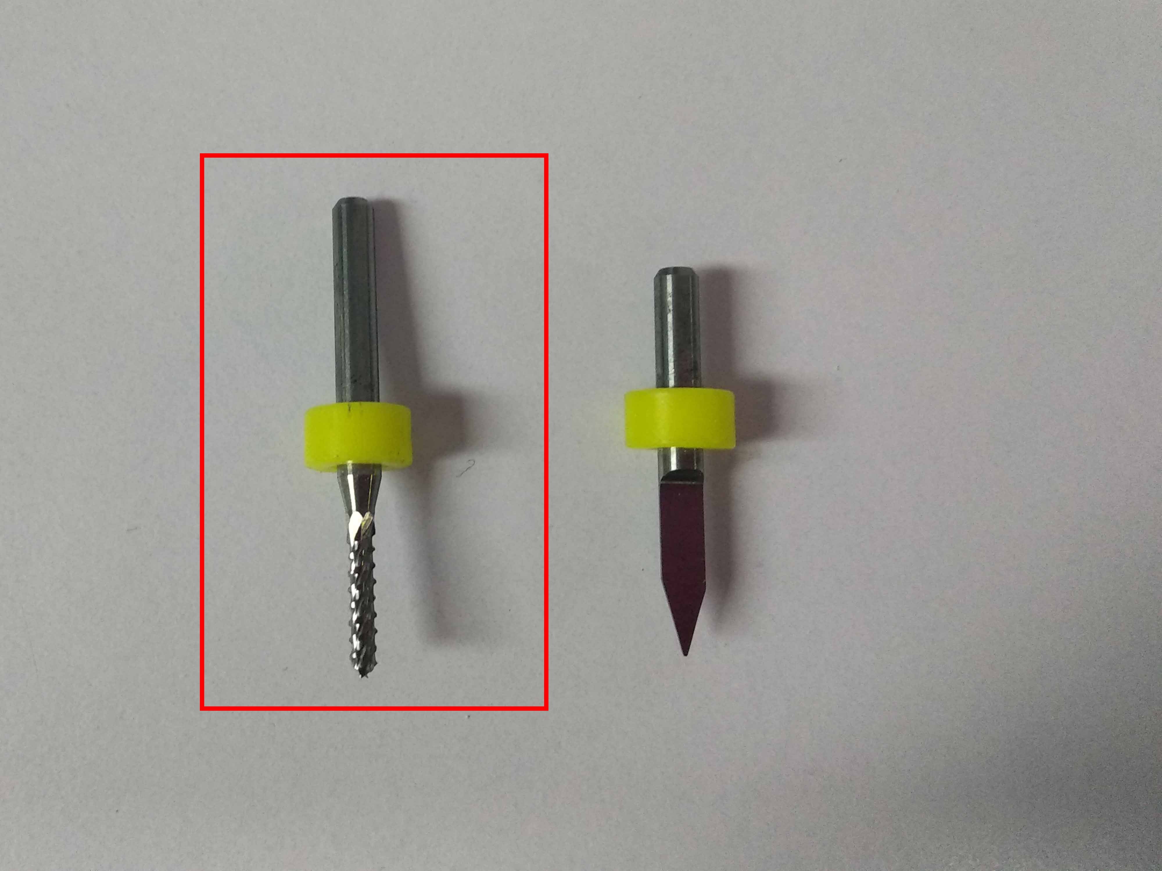
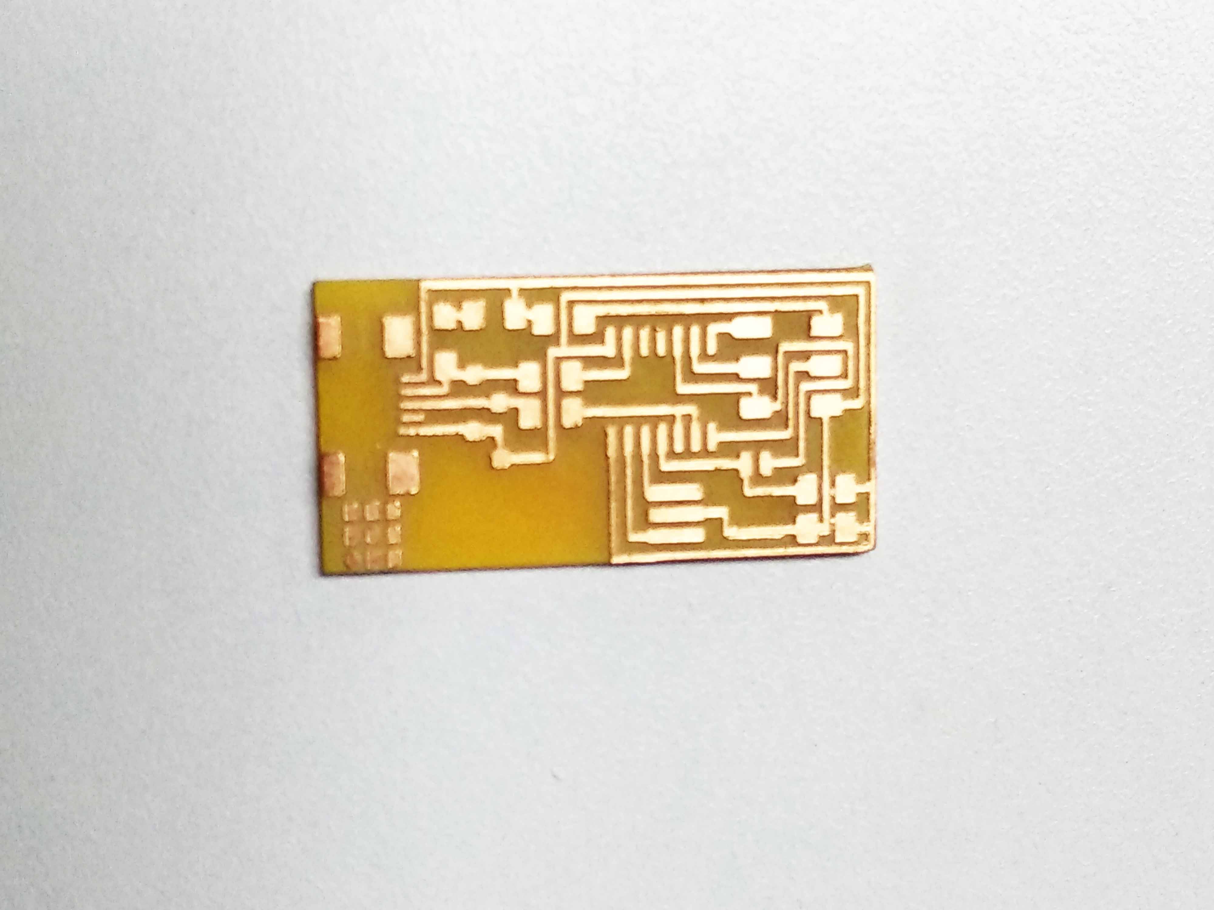
2 mm cutting bit
machine output
Step4:FAB ISP Soldering
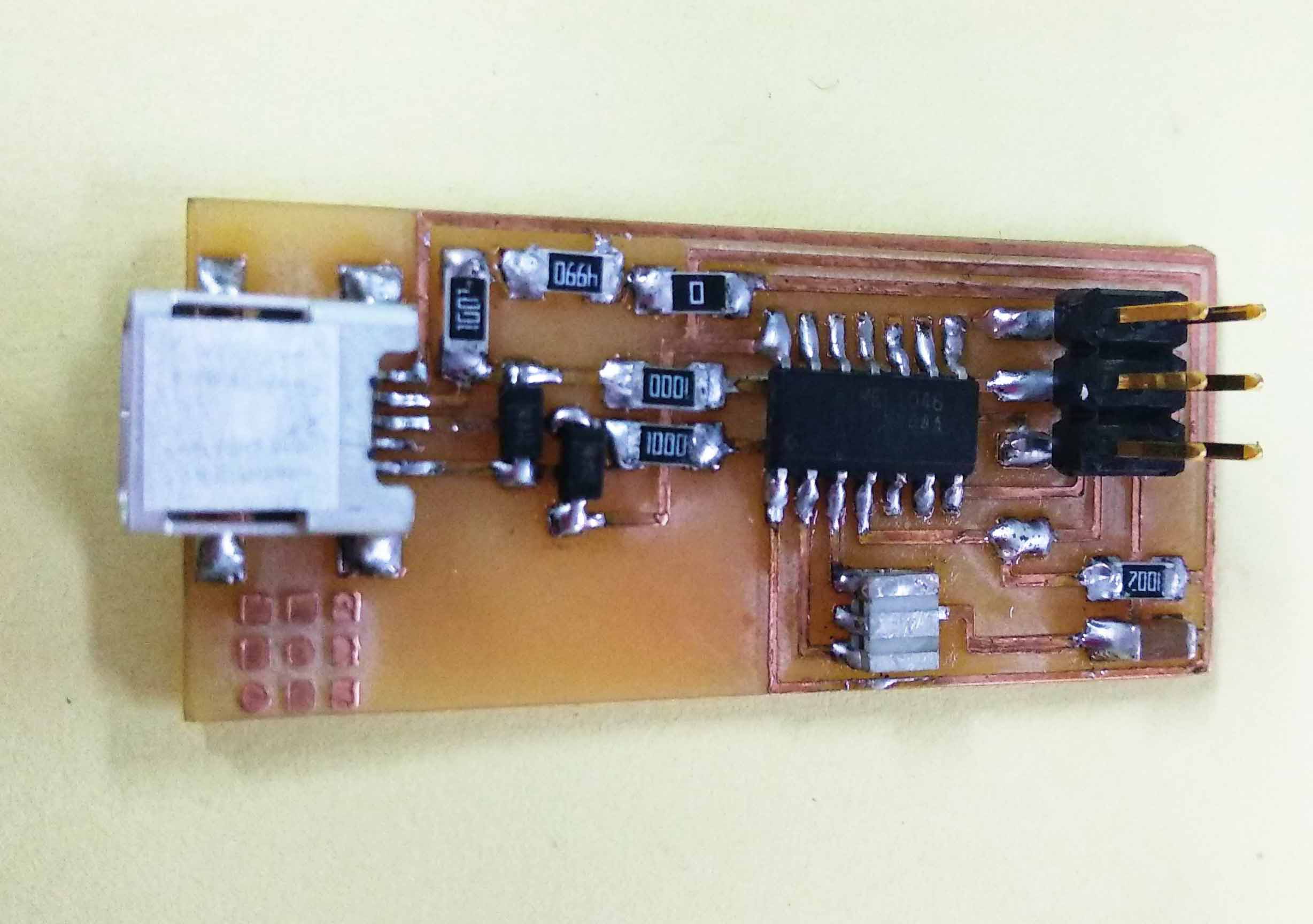
I opened the tutorial file Prepared the components and tools and followed the soldering instructions except that I soldered the mini USB at the end because it was higher than other components and I was afraid it will annoy me while working if I solidered in the beiginning.
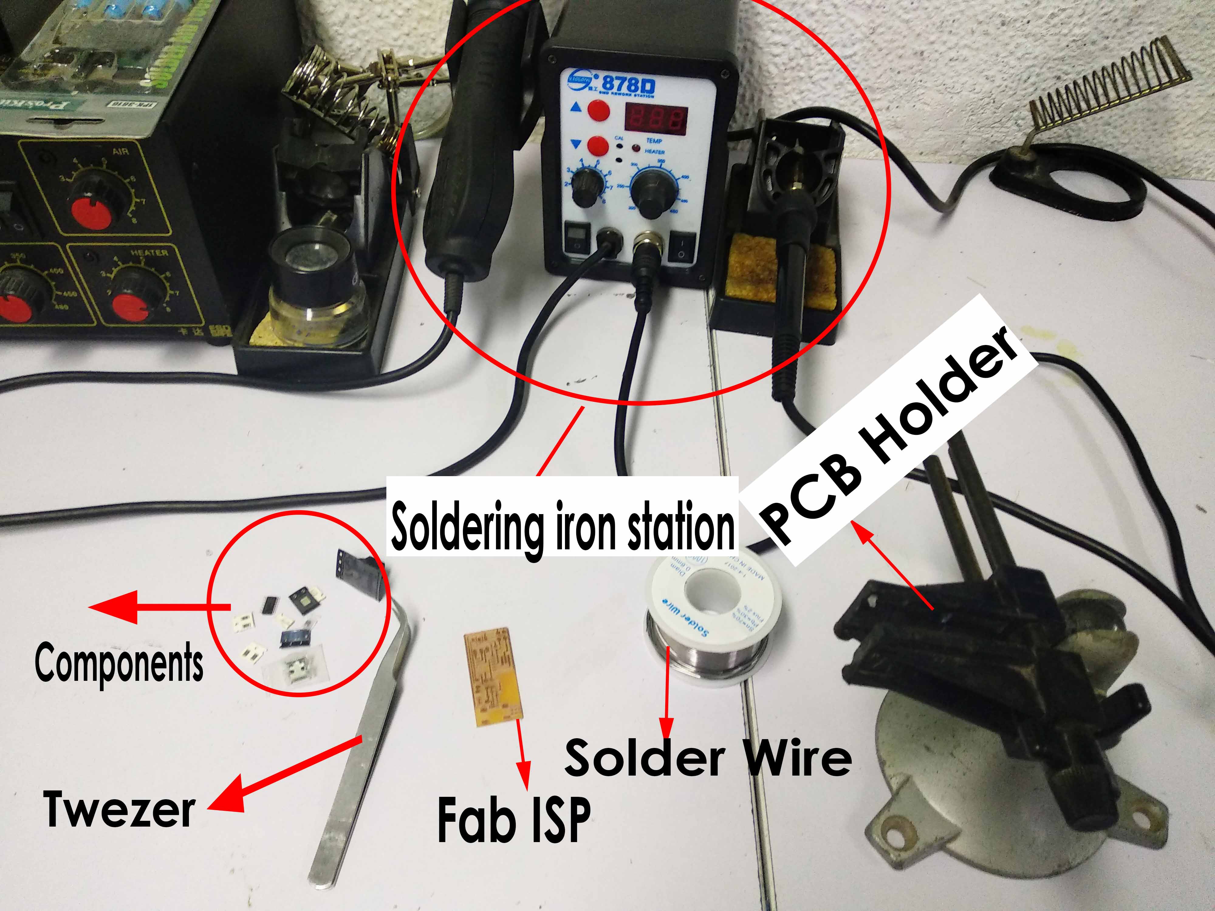
I used the holder to fix the PCB and make it easy to solder. I started with resistors then capacitors and ziner after that the ATtiny 44, The headers and finally the mini USB.
The technique I used was to tin the pads, Hold the component with tweezer and put it over the tinned pads, heat again and push the component till it's well soldered.
THE FINAL RESULT

Step5:FAB ISP programming
To program the Fab ISP that's going to be a programmer for another board you have to had a Fab ISP first ! I didn't have another working ISP and I found tutorials that Arduino it self can be used as an ISP programmer for AVR microcontrollers, So I went for this option and I used it to program the Fab ISP.
- Make the Arduino As an ISP programmer
- Heartbeat - shows the programmer is running
- Error - Lights up if something goes wrong (use red if that makes sense)
- Programming - In communication with the slave
- Connect Fab ISP to the Arduino
- Backup enviroment PATH and download WinAVR
- Enviroment Variables:Environment variables hold values related to the current environment, like the Operating System or user sessions. These variables are dynamic and affect the way running processes will behave on computer.
- Enviroment Path: is an environment variable on operating systems that specify a set of directories where executable programs are located.Each executing process or user session has its own PATH setting.
- Upload the code
After reading this tutorial on Arduino Website, I figured out that there is a code that should be downloaded to the arduino first. This code turns the Arduino to AVR ISP. I connected a led circuit also that gives an indication if the code is downloaded successfully and running.
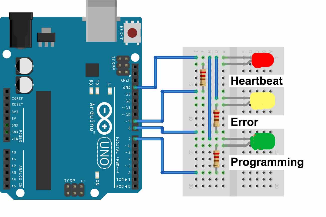
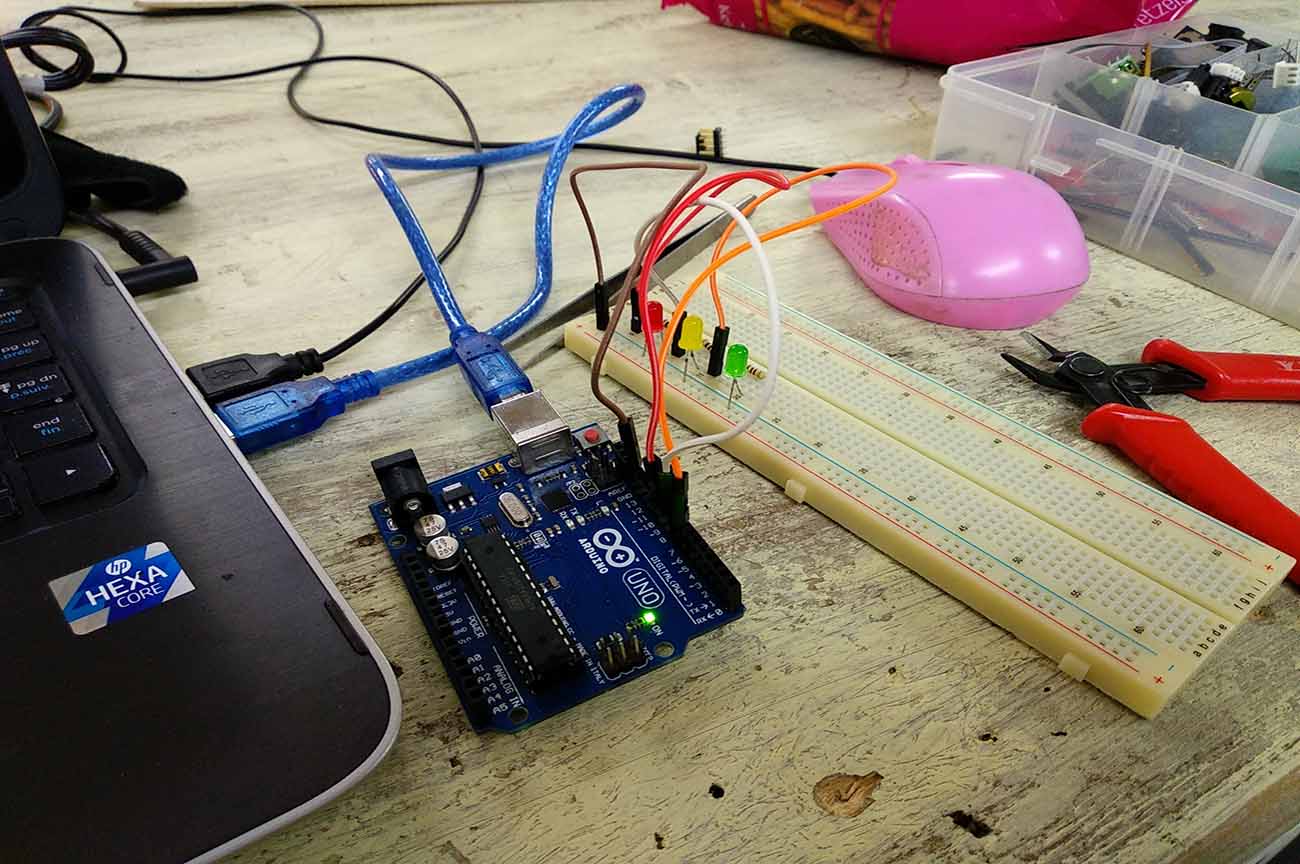
This circuit is for visual feed back
I connected the same circuit and pluged the Arduino into my Labtop.
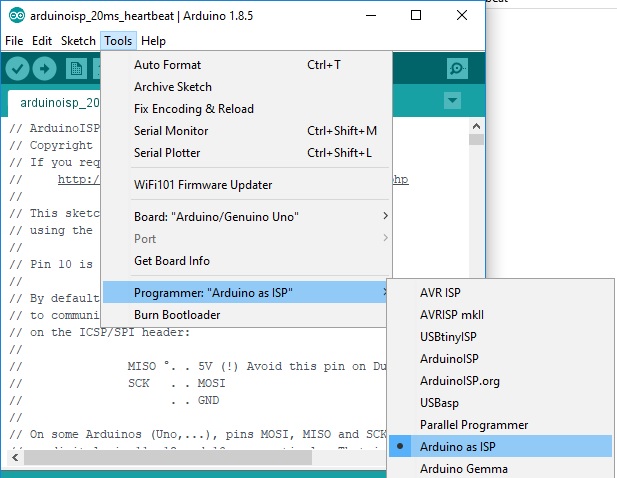
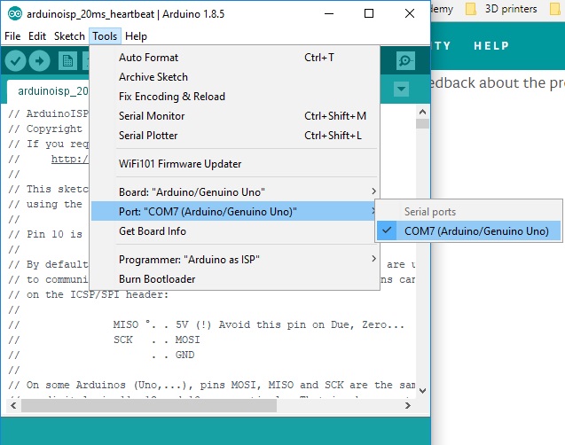
I open the Code then from tools I selected the Arduino as an ISP.
I made sure that the right com port on which the Arduino is connected is selected.After thst I uploaded the code.
The visual feedback circuit should act as the following:
After Uploading the code it worked well and the code was uploaded successfully
Now the Arduino Board is ready to act as an ISP programmer and I will use it to program my Fab ISP
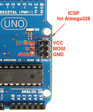
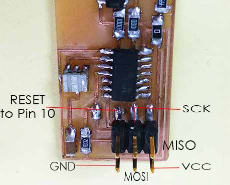
I connected the right pins to each other between the Arduino and FAB ISP except the reset pin of the Fab ISP should be connected to pin 10 on the arduino board and the reset pin on the Arduino is connected to nothing.Also a capacitor should be connected between reset and ground pins.
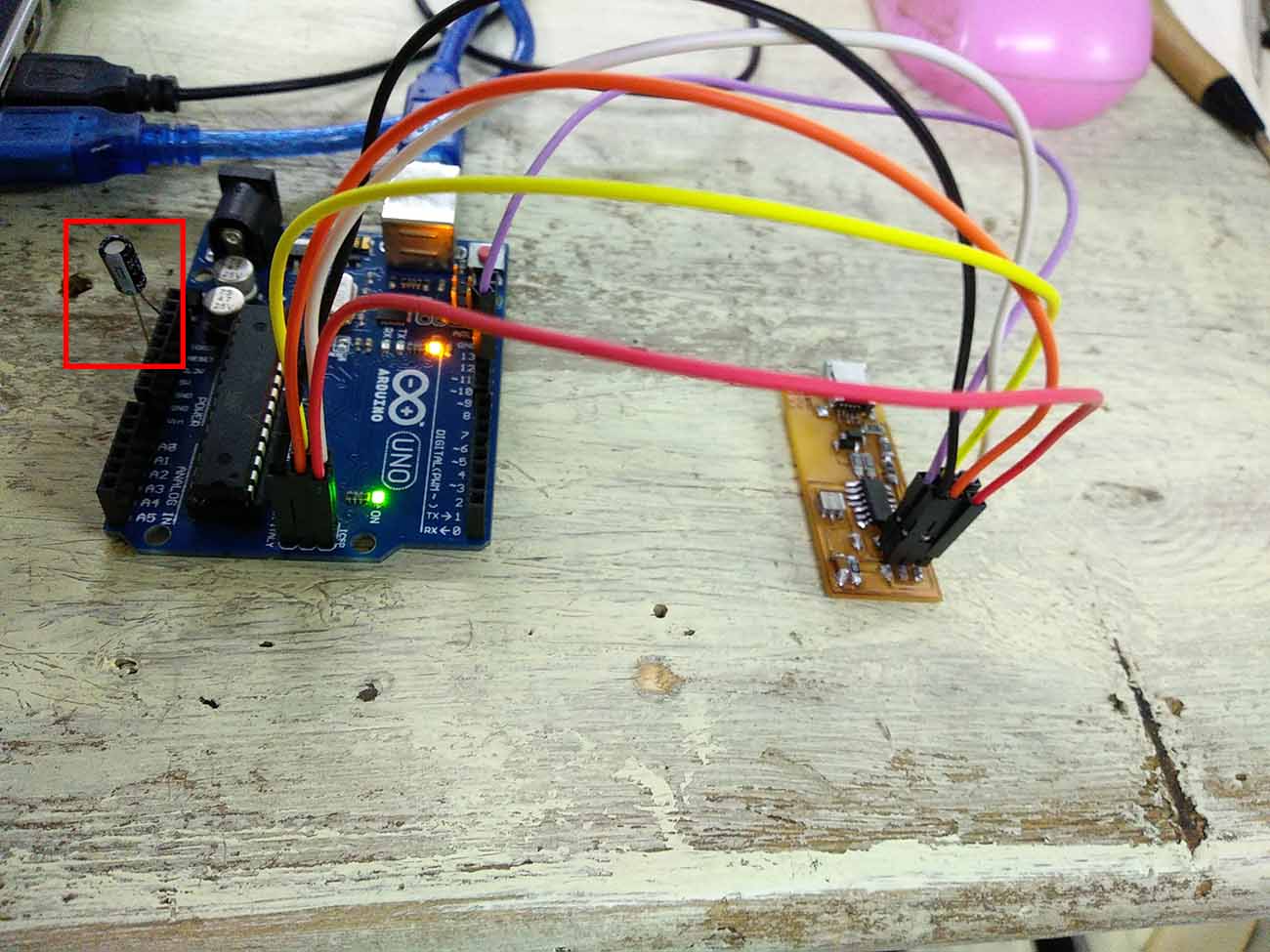
The capacitor should be connected to absorb the reset signal while programming to allow programming through the board not progrmming it.
We backup the path because may be while installing WinAVR all the directories on the path will be replaced with the WinAVR path and this will affect all the processes running on the computer.
Open regedit from windows search then go to HKEY_LOCAL_MACHINE\SYSTEM\CurrentControlSet\Control\Session Manager\Environment.
Right click on the path then modify and copy its content to any word file.
Download WinAVR then compare the new path content with the old one backed up. If it's changed then we will add semicolon then copy and paste the old path content. For me it was added already so I did nothing.
DownloadFab ISP firmware then un zip the file.
Open make file in the fab ISP firmware folder with Brackets
Change the com number to the com on which Arduino board is connected to.
Open windows command prompet then change directory to the firmware folder, Type make clean then type make hex.Errors appeared and I neglected it.
Type make fuse and wait till verifying and writing.
After a sentence of fuse ok appears, Type make program.
Another fuse ok appeared and this means the program is successfully installed.
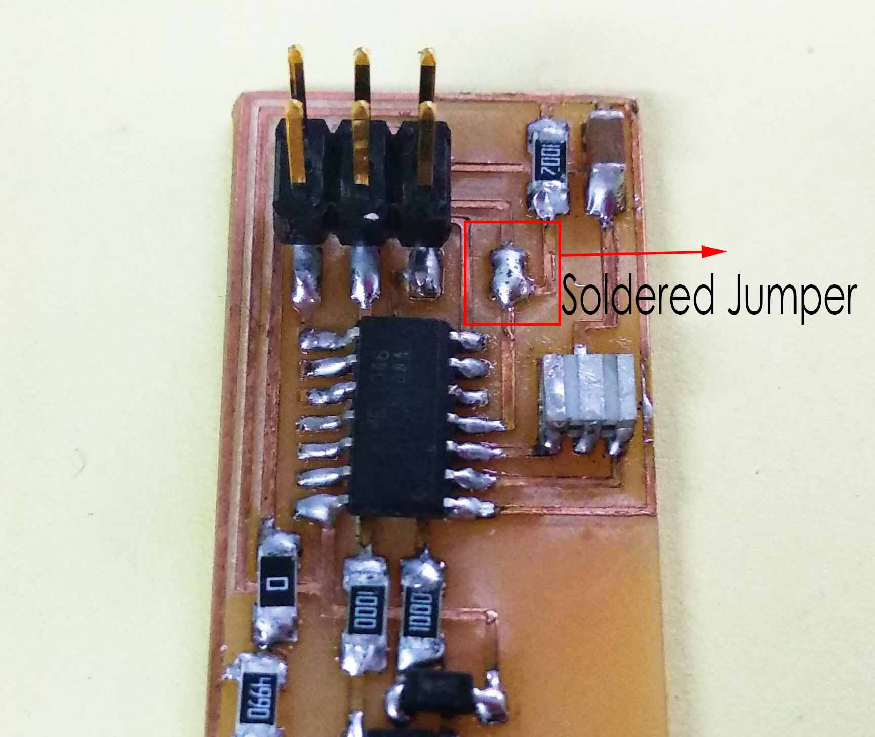
The soldered jumper should be removed to prevent any program from being uploaded to the fab ISP.
The board is programmed successfully!!
Resources I used in this week:
- Fab Academy week4 tutorials
- Jackob Nelsson documentation
- Arduino tutorial about "Arduino as ISP and arduino bootloaders.
- Fab Academy tutorial about Fab ISP programming
- Wikipedia

