Final Project Development
Bike navigation system
A simple, distraction free, turn-by-turn navigation system for bikes.
I’m a cyclist and taking your phone out of our pocket to check if you’re going the right way isn’t good. Other than difficult, it is actually pretty dangerous as most of us do it while pedaling.
My goal is to make bikes a little bit more smart. Starting with navigation, and if there’s enough time, I’ll add more features.
For trails or countryside rides, it’s ok to have a big gps or your phone attached to the handlebar. But, for cities, you don’t want to get distracted, there’s a lot going on already. And for the sake of not getting robbed, placing a $1000 phone on your bike is not a good way to be discrete.
So my idea is to build a device that will safely guide the cyclist throughout the route without being distracting.
Since it is going to be installed on a bike, it needs to meet a couple of other requirements:
- Easy to use
- Fit multiple handles
- Waterproof
- Difficult to steal
And it would be cool if it was/has:
- Sensors for data gathering
- Self-powered
- Anti-theft
- Safety emergency crash alert
Weekly development
I want to use each weeks assignments to develop the final project. For that, I’ll use a weekly development section to document everything.
Week 1
Research
I’ve actually found a couple of ready products / concepts on the internet and I’m going to add them here as a reference. It actually proves the necessity of the product.
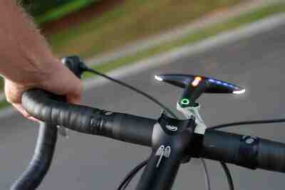
Ref: http://hammerhead.io
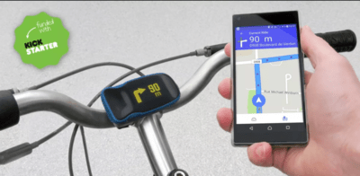
Ref: http://haiku.bike
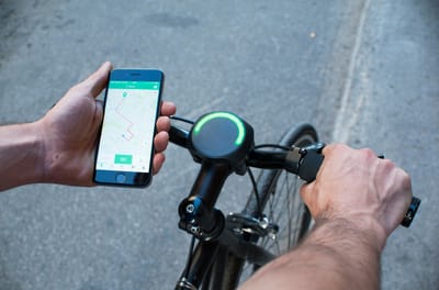
Ref: http://www.smarthalo.bike/
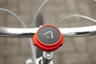
Ref: http://beeline.co/
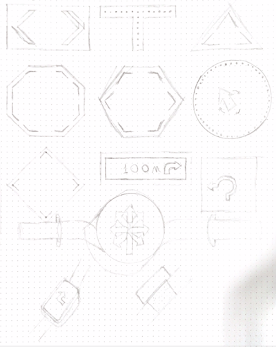
First sketches
Week 2
Built this beautiful website
Week 3
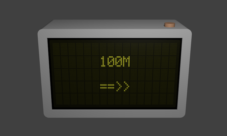
First render
Week 4
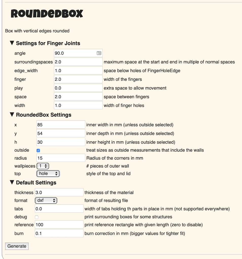
Laser cut enclosure

After using the laser cutter, I wanted to create a first version of a case to the device. I found a great box generator boxes.py and tried it. Looks like it’s a great start for a mockup.
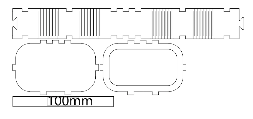
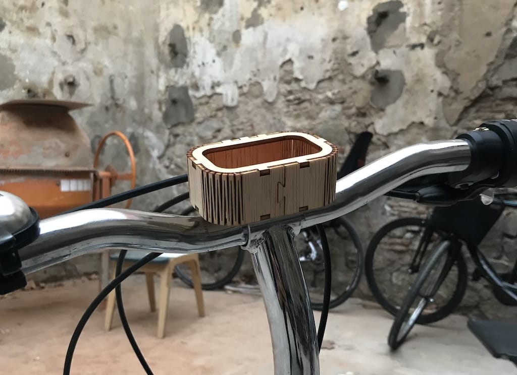
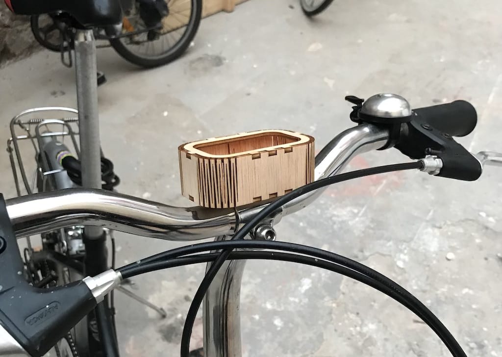
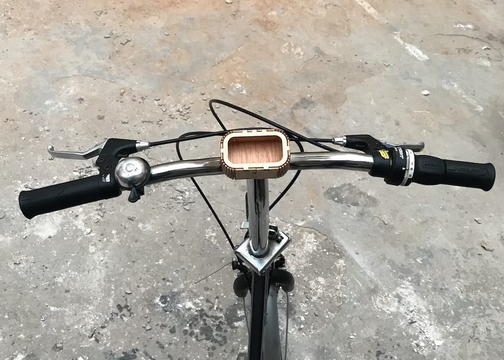
This mockup was really helpful to visualize the device and start thinking of ways to fix it on the handle, distribute the electronics inside, etc.
I’ll probably do another iteration soon.
Week 5
Got a display
The goal of this week as mainly get a hang of the process of milling a PCB, SMD soldering and programing a micro controller. But, I wanted to go ahead and figure what display and possible battery to use.
So far, I got a regular 16x2 display the lab had available. I wanted it to be a little bit taller, maybe 16x4. But this is something I can start working with and change in the future IF necessary.
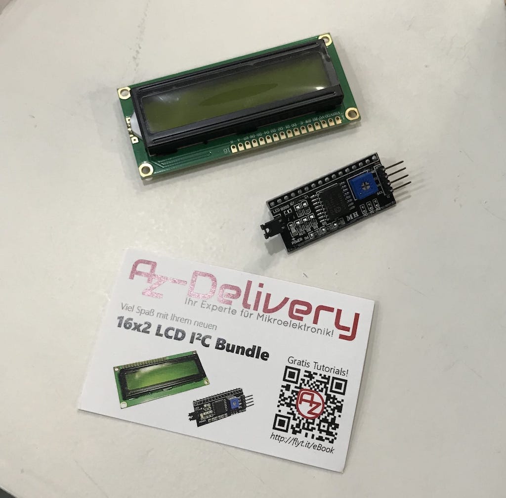
So for the next week I’ll be designing a case with this display in mind.
Week 6
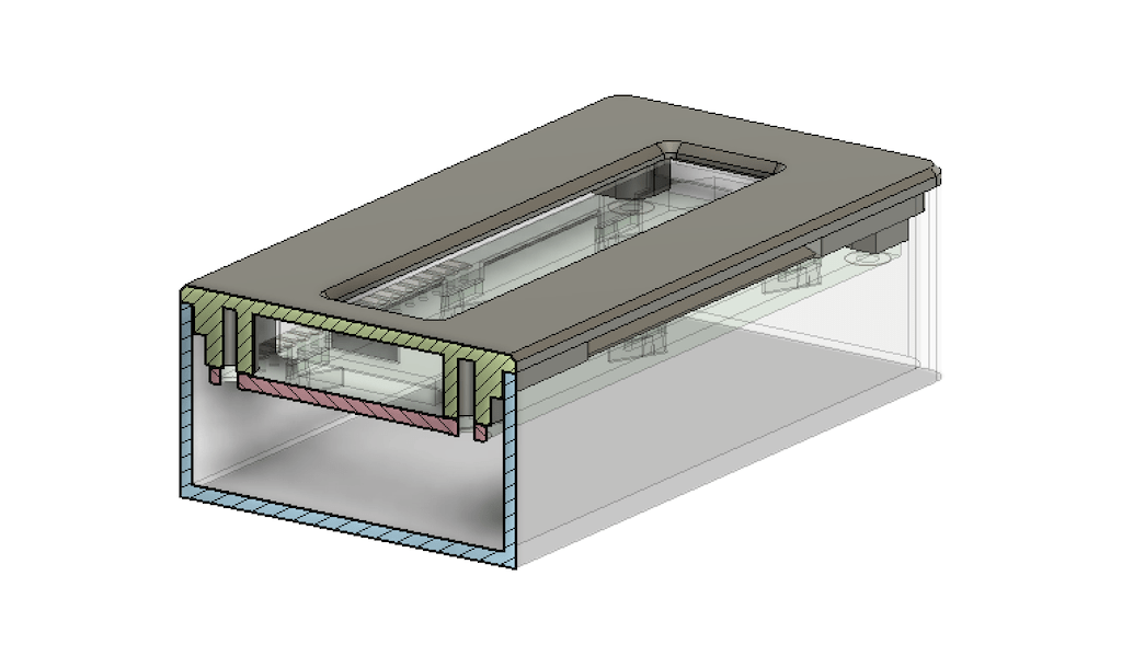
3D printed enclosure
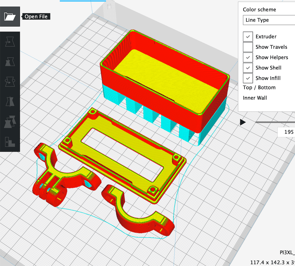
I used this week’s assignments to model and print an enclosure for my device. I still don’t have all the components but I believe the display is what will determine the final shape. So I used it as a base for the design.
Then, I printed everything
The design I got required using rubber or foam pads to increase fixation, I tried EVA foam but it is still sliding a bit. I’m gonna either try rubber or a different design.
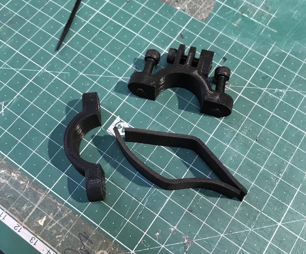
But other than that, I’m pretty happy with the result.
Got an Arduino
I wanted to start working with the code / networking of the project. Mainly because I have no idea how to do it, and I know there will be lots of difficulties. So better start now.
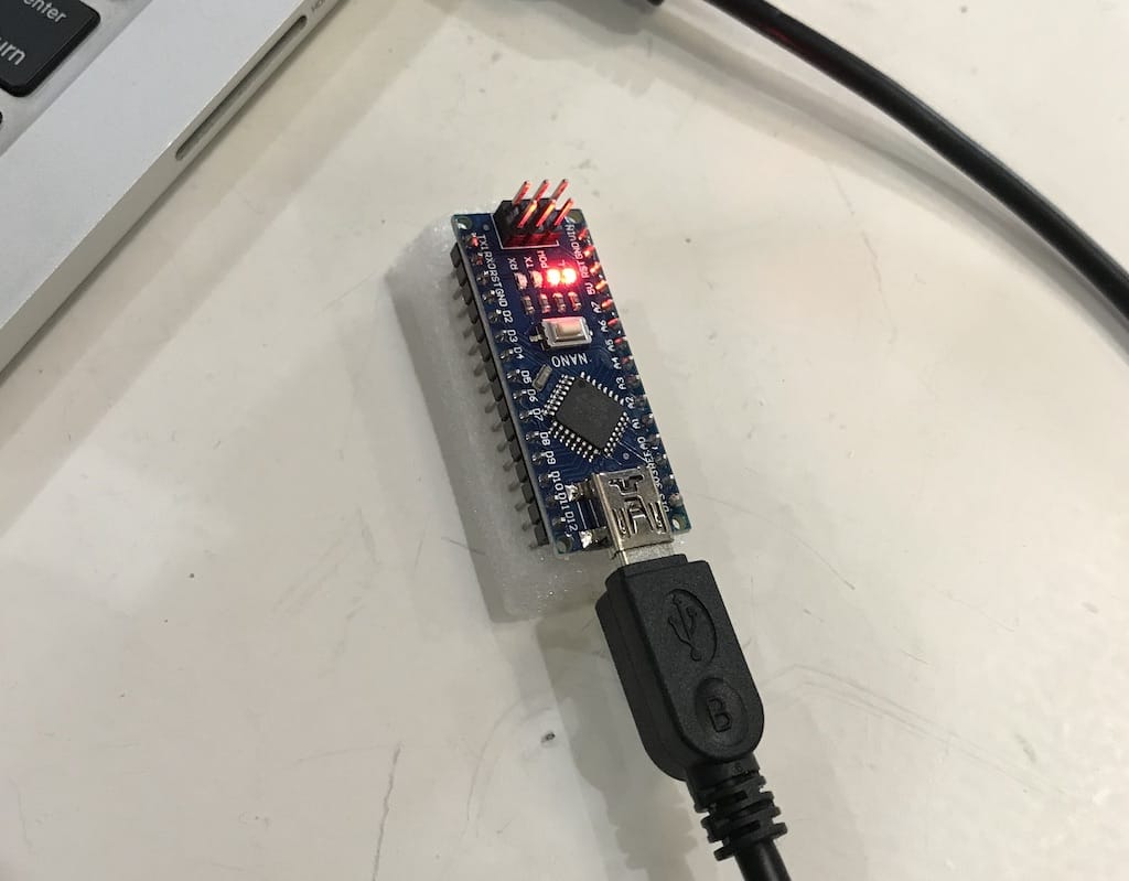
The lab had a couple of Arduino nanos, so I grabbed one.
Installed the IDE and uploaded a blink program to test it.
This version uses the ATMega328P (Old bootloader).
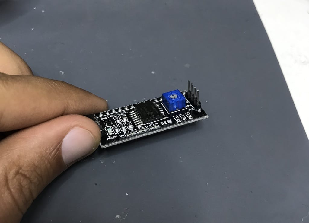
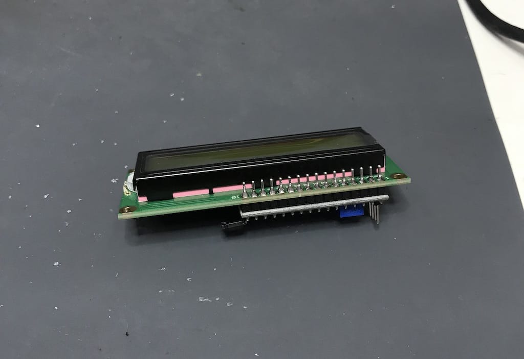
Since it was ok. It was time to hook the display and test it as well. But before, I had to solder the i2c adaptor to the display itself.
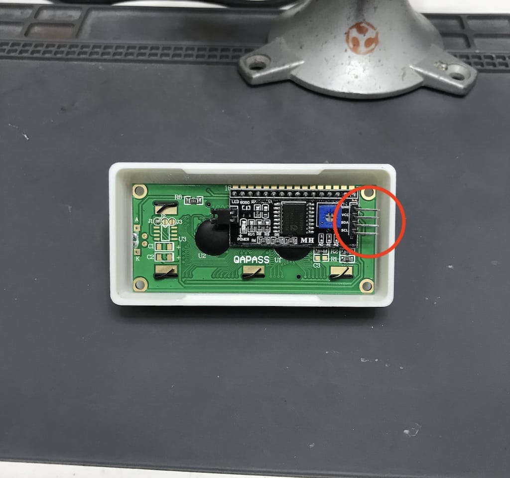
But as soon as I placed the boards together, I realized there wasn’t be enough room for the connectors. So I had to replace them.
After that I was able to solder the rest.
Then, I connected everything following the instructions and loaded a simple program. But for some reason it wasn’t showing anything other than turning the display on.
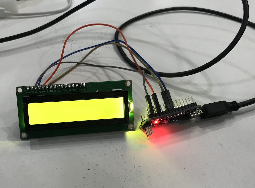
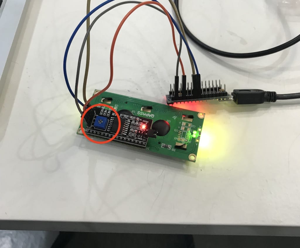
After a little bit of reading I figured there is a potentiometer that should be adjusted in order to correctly print the text.
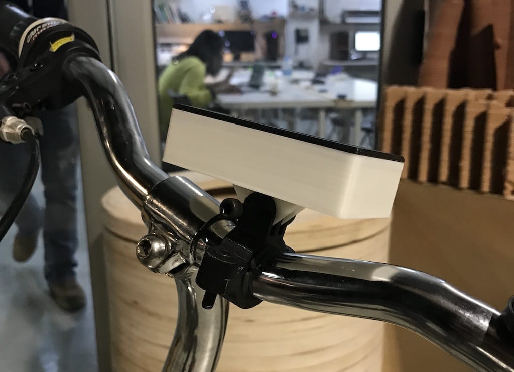
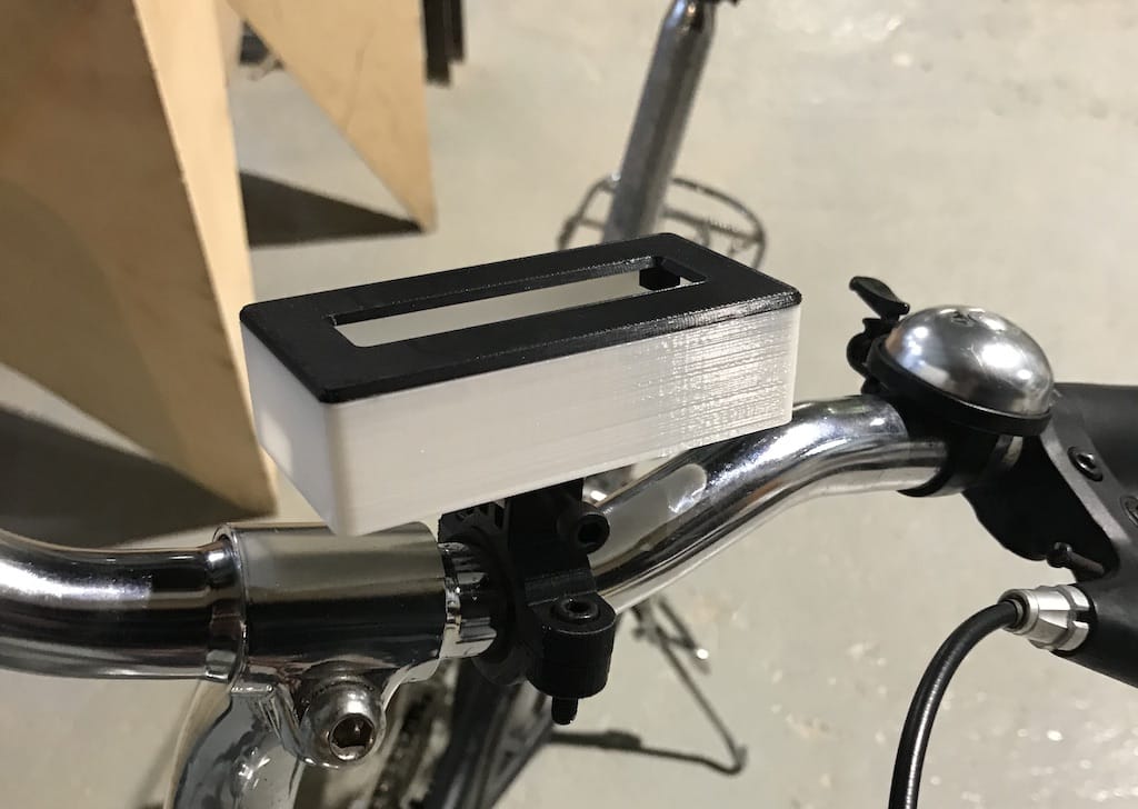
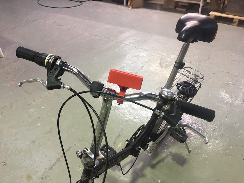
Mockup with an actual display
I was so excited that I wanted to see how it looked on the bike itself. So I got a power bank and realized everything would not fit inside the enclosure. One of the beauties about rapid prototyping is just getting a drill and making the holes you need. Because you can edit your design and make it right on a next iteration.
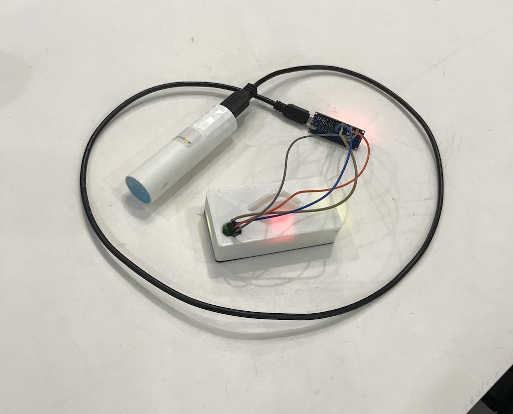
Here we have the hero shot of the day. (Of course hiding the components that were hanging out haha)
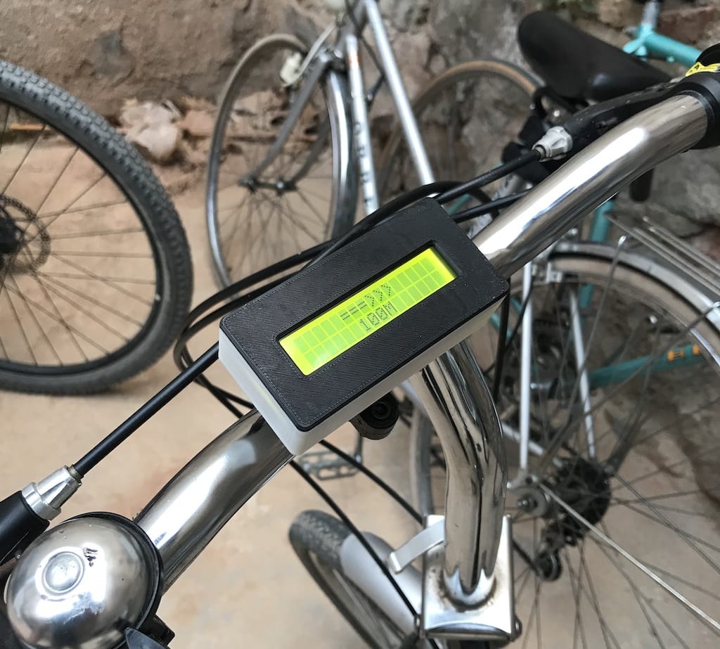
I’m pretty satisfied with this weeks result.
Week 7
App / API Research
I started thinking about how the device would work. If it would receive a directions list and use its own gps to navigate it, or the phone would do everything and just send the next turn to the screen.
All the commercial solutions out have their own apps. But, for now, I’d like to find an easier way to send turn-by-turn navigation to my device.
I know google maps sends next-turn voice directions automatically when you have a bluetooth audio device connected. May be able to hack that but I doubt this will give a good result.
After a little bit of research, even their API does not allow using it to create your own navigation system. So I’ll have to look into some other mapping app.
A friend of mine is the manager of my city’s geotagging sector. So I asked what he knew about it and he gave me great directions.
osmand is a great opensource navigation app, may be able to tweak it.
OpenStreetMap has wiki pages on iOS and Android applications using its maps
ffwdmejs is a JavaScript based online navigation. May be useful as well somehow.
Week 9
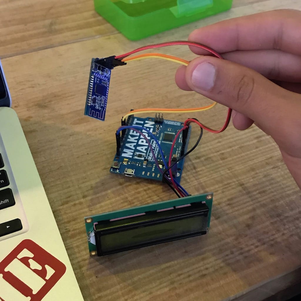
Started this week by getting a SH-HC-08 Bluetooth adaptor for my device. I want to understand better how it works so I can integrate it with my device.
Since I have no idea how it works. First step is always to google some kind of instruction.
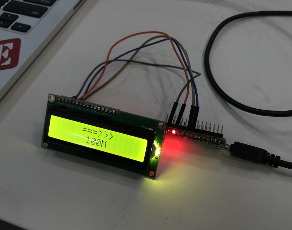
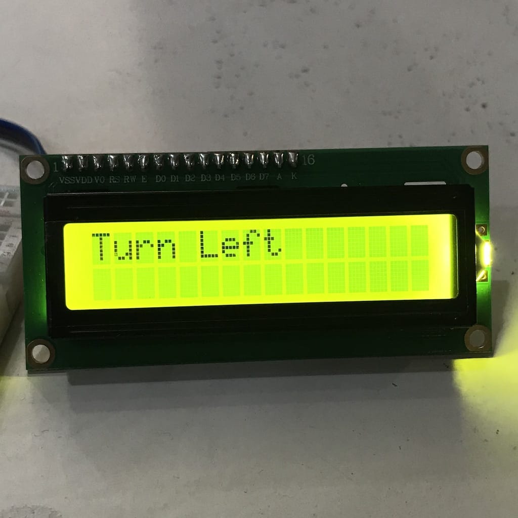
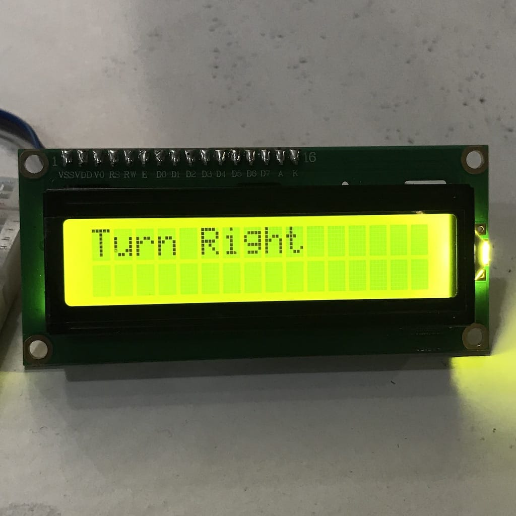
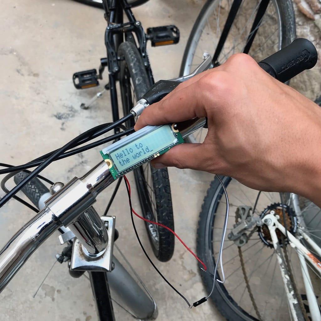
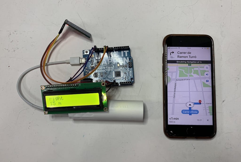
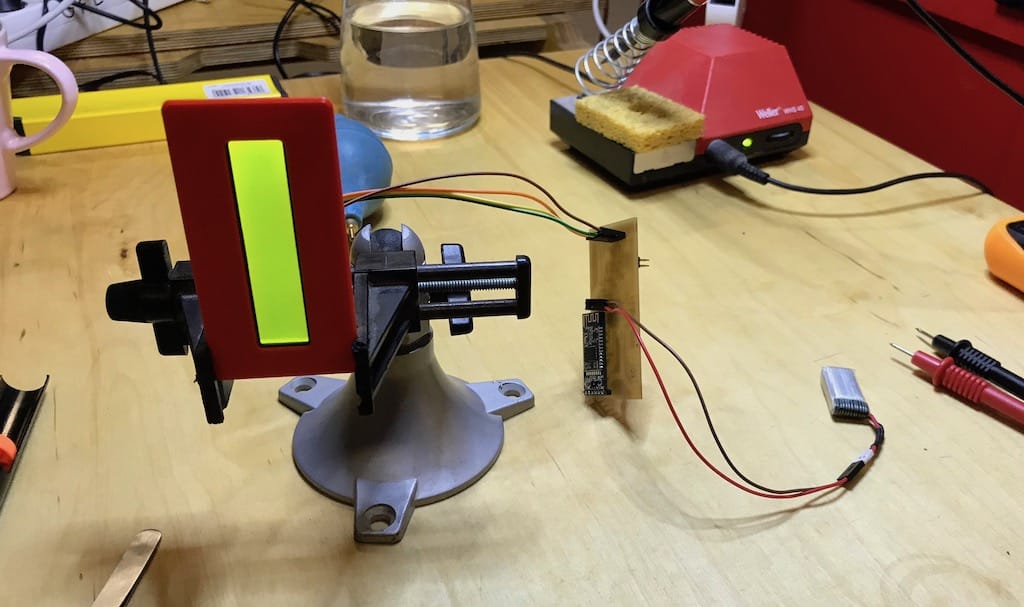
Found a really basic youtube video showing how to wire and program the board to light an LED with a bluetooth command. So I copied the code and changed it to show directions on the LCD screen.
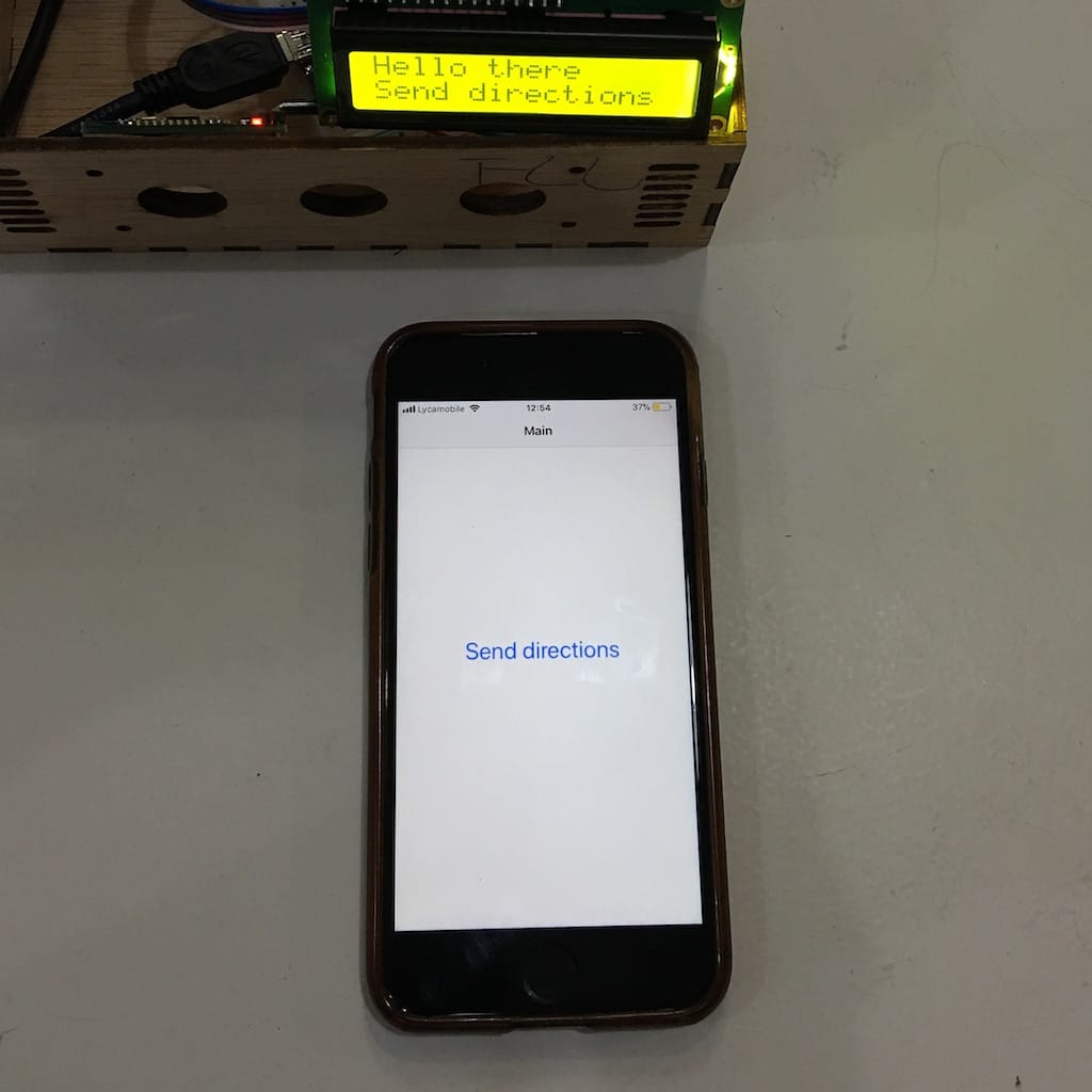
After wiring everything, I was able to light the LCD screen and connect to bluetooth.

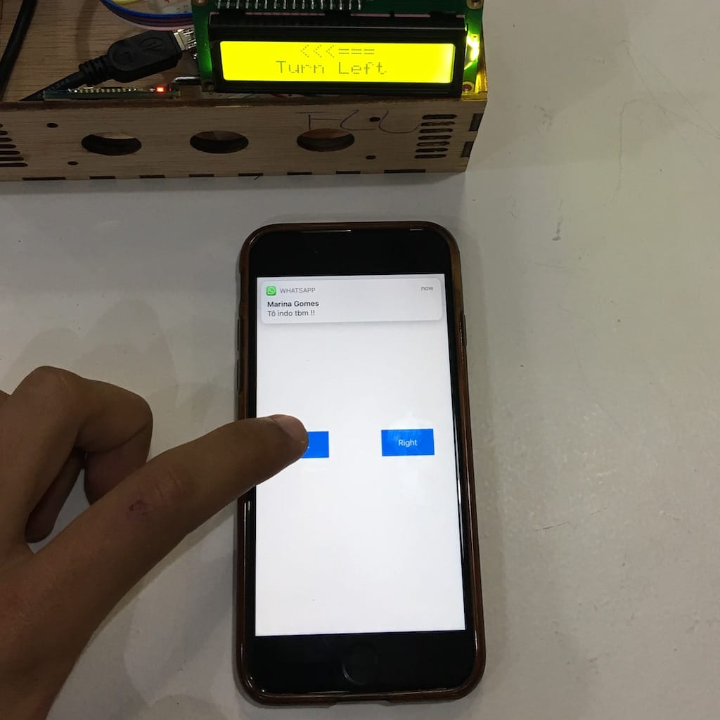
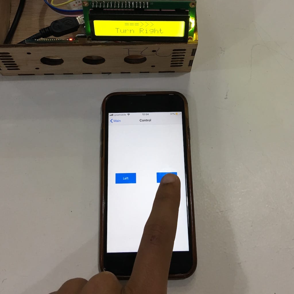
Then, updated the code and was able to send directions from the phone via the bluetooth terminal app.
But, since I’ll have to integrate with a map, I believe the best way is to create my own app and send the directions to the display.
Spent a couple of hours trying to figure everything out. I still don’t understand much but was able to create an app to connect and send the characters to the Arduino.
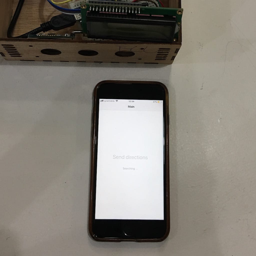
For now I’ll head back to the weeks assignments to dive deeper and better understand how everything works.
Week 10
Started reading about waterproof enclosure design
Then, I found this thesis on Design and Prototyping of a Waterproof Probe Enclosure. For an Industrial Design Engineering masters program at Royal Institute of Technology (KTH), Stockholm. By Eric Lindqvist and Nikolaj Strömberg Gröndahl.
What struck me the most, is that the device itself is really similar to my own. So there is A LOT of useful informations in there.
The greatest thing is that they start from describing the problem they had to solve. Go through the theory of seal designs, materials, manufacturing processes. Then, show all iterations of the design. And finally, develop the final prototype.
So far, this has been a huge inspiration into the design of project.
Week 11
I just realized my project did not have a sensor until now! All the time I was relying on the phone to calculate the route and send it to the display. But it would be nice to have at least an accelerometer and a gyro to add some features.
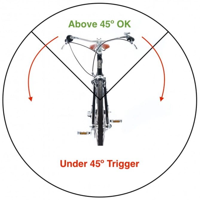
A really important one is regarding safety. If the cyclist crashes or falls, I can sense it and trigger an action. As sending a SMS or call to emergency. This could be really useful. Specially for solo adventurers.
I made a board for this week but managed to burn it afterwards. So for my testing I’ll use a commercial sensor we have here.
IMU 10DOF MPU6050+HMC5883L+BMP085
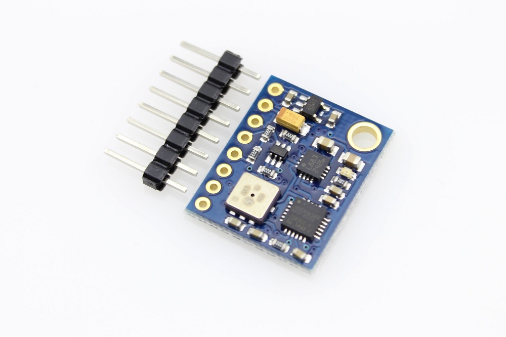
Used this example to test the board and it looks fine.
Now I’m going to decide the best way to set up the trigger and then program the board.
Week 12
Found a smaller 16x2 display and made a board that actually fit it. So now I’ll try adding everything to it.
One of my concerns was its performance under the sun. So far, it looks like it’s going to work just fine for a first version.
Another great option is using an e-ink display.
Week 13
Since we’re going on a break right now. I’ll setup the prototype with an Arduino again. So I can start further understanding how everything will work.
One problem I had using an ATmega328 was having to disconnect TX and RX jumpers every time I wanted to upload a new code through USB. So I looked around and found a board with an ATmega32u4, that has hardware USB and don’t use those pins. So I can have everything connected at all times.
Another advantage was not needing a breadboard anymore. With this setup I could jumper everything straight into the board.
Found this code on github that displays whatever is sent through bluetooth, for now, I don’t need anything else.
Week 14
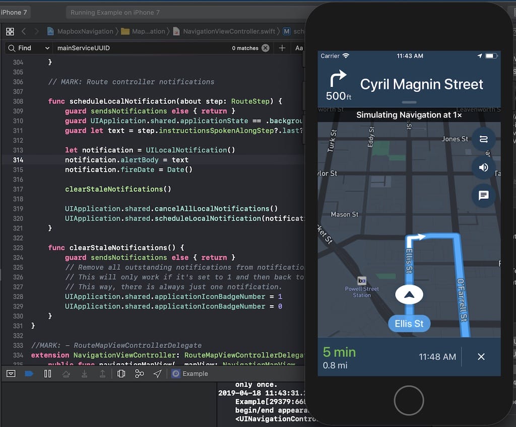
Now that the electronics is ready, I need to start working on the navigation itself. Thankfully, after talking to a couple of people. I found Mapbox iOS examples
In less than an hour I have a fully working navigation app within my development environment, to make anything I want. That’s too exciting!
So from here, I have two ways: trimming down the examples until I get to where I want, or, build only what I need.
In any case, I still need to understand better how navigation and BLE works. So I’ll do further reading. Then, to not get crazy, I’ll build each block individually and only after bring everything together.
But, I’m confident that by the end of the holiday I’ll have a fully integrated prototype.
After a lot of effort during the weekend, I managed to make everything talk. Of course it still needs a lot of tweaks and improvements, but it’s working.
Week 17
Got an E-ink Display to try. If it works it will be a great solution to show more information and save battery.

Bummer doc says it shouldn’t be refreshed more than every 180 secs
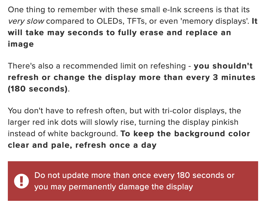
After wiring and loading the libraries, I got it working. But the amount of flickering the screen does to update would be super distractive. Contradicting the point of using the device.
Week 18
My goal is to finish the first version of the final board. Giving me the possibility to use the wildcard assignment to create an injected plastic enclosure for example.
I was holding it too much because I had yet not defined the display and battery. But certainly this got me a bit off track. So I’ll make it and if needed edit the design later.
MCU with battery
One of the requisites of the project is having a battery charger and drawing power from it.
After talking with a couple instructors I’ve decided to use the Adafruit Feather 32u4 Proto as a starting point of my board design. From there I’ll add the display, bluetooth module and accelerometer.
The only problem is that the board drawing is “complex”, with small packagings and a two sided board. My project is way simpler and don’t need all of that. Thankfully, using the fabacademy search tool, I found the Aquapionner’s page linking to the FABLEO project. Way simpler and a better starting point. From this, I’ll remove the unnecessary components and add the battery charging part from the Feather.
Original Fab Leo
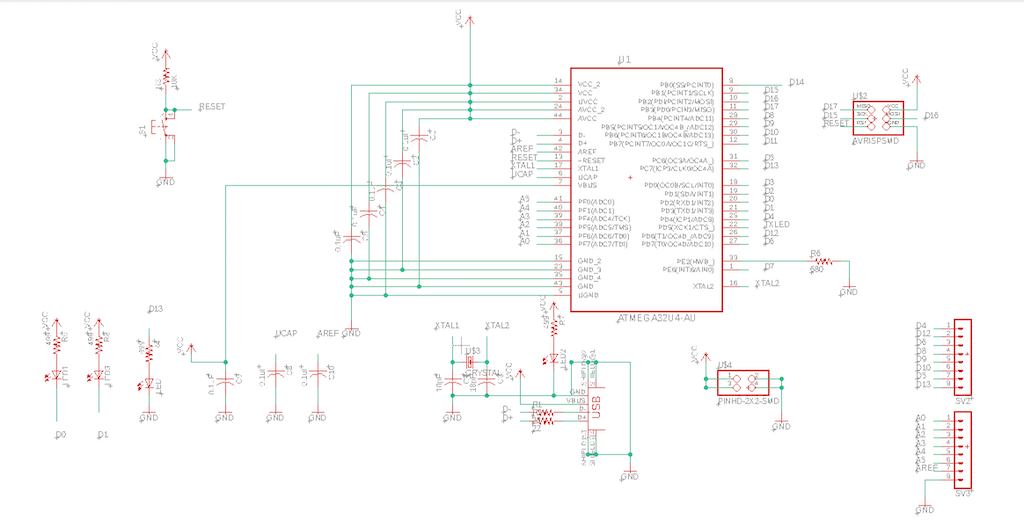
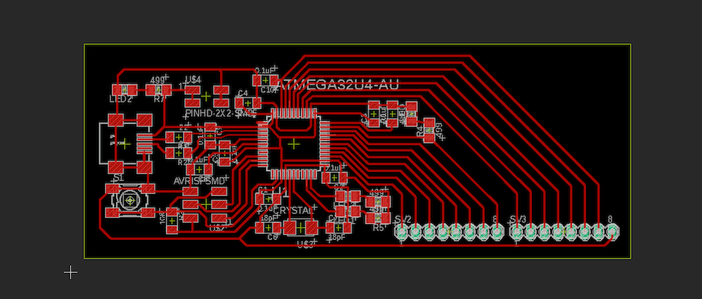
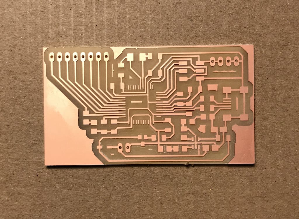
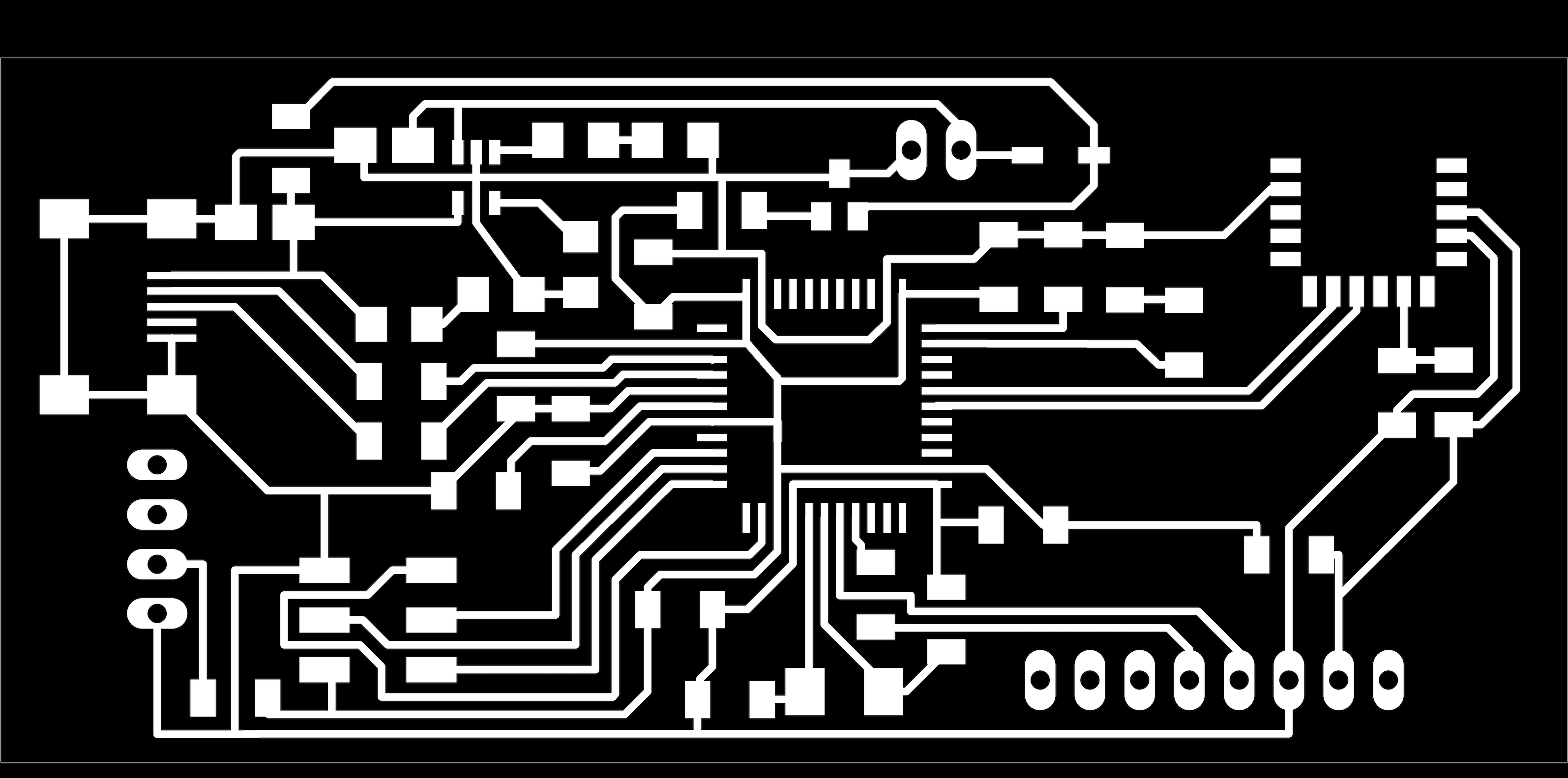
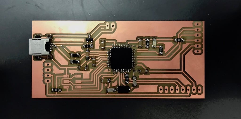
My final board v1
Mainly the changes were taking off extra LEDs and components I wouldn’t use. And including the charging logic from the feather board.
During the milling process, I made a mistake with one of the images. Instead of making the background black, I should have done it white.
Don’t do this
Instead, you should do this
Week 19
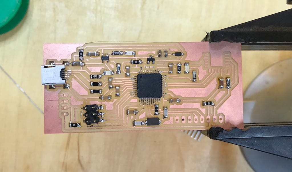
After soldering, connected to usb and the power LED worked. This, plus not having a warning on the computer means there are no power shorts.
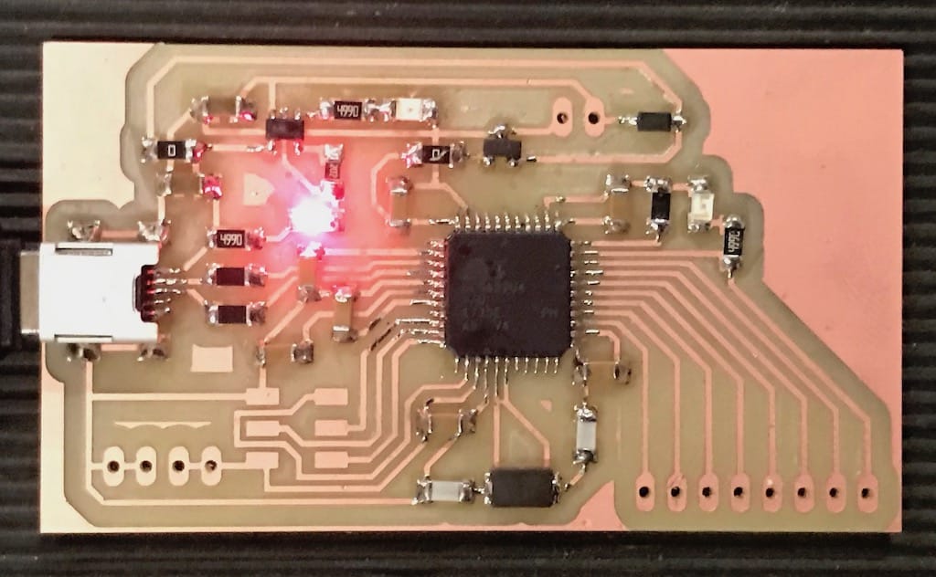
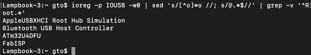
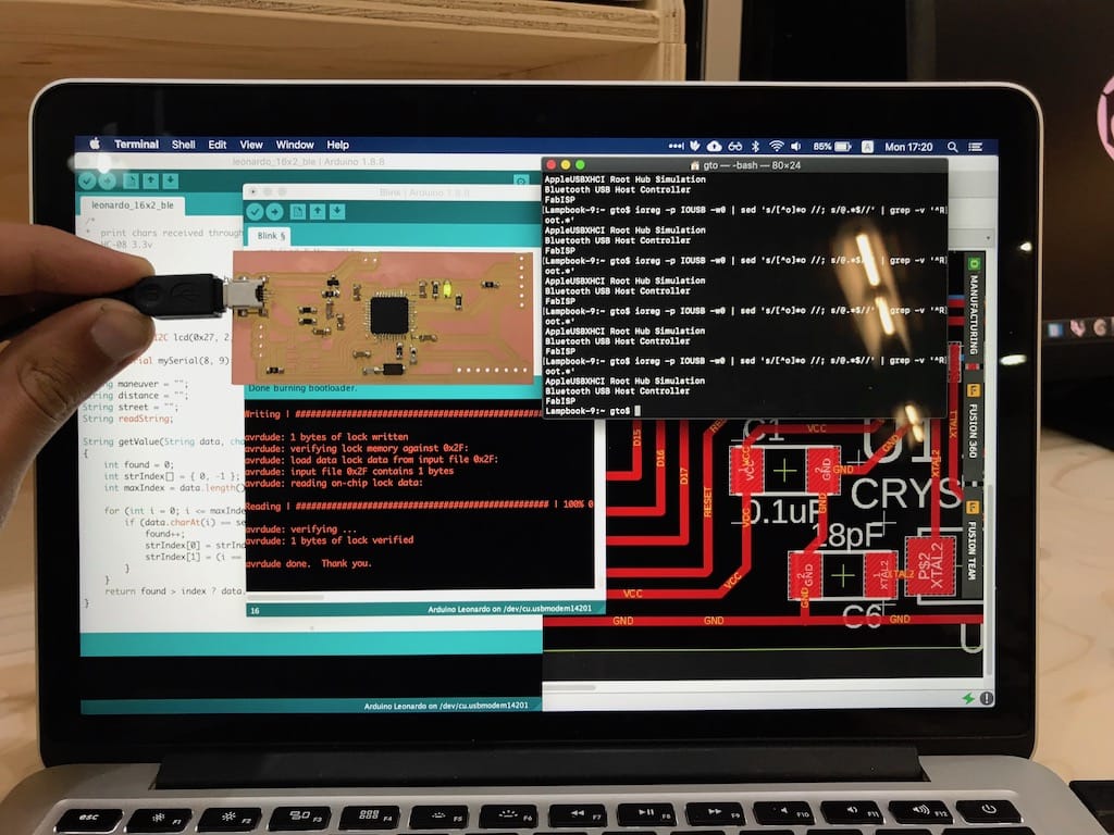
But then I checked if the device was being detected by the computer and nothing showed up.
ioreg -p IOUSB -w0 | sed 's/[^o]*o //; s/@.*$//' | grep -v '^Root.*'
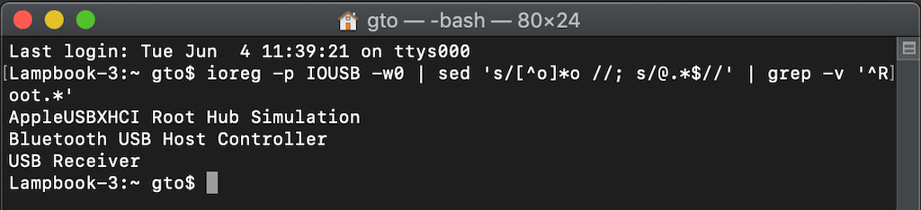
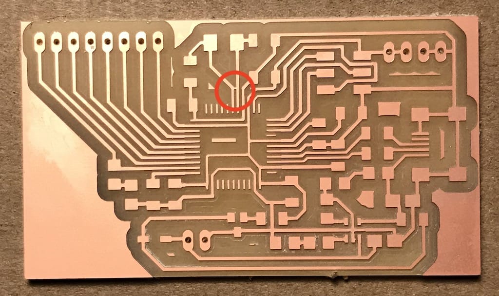
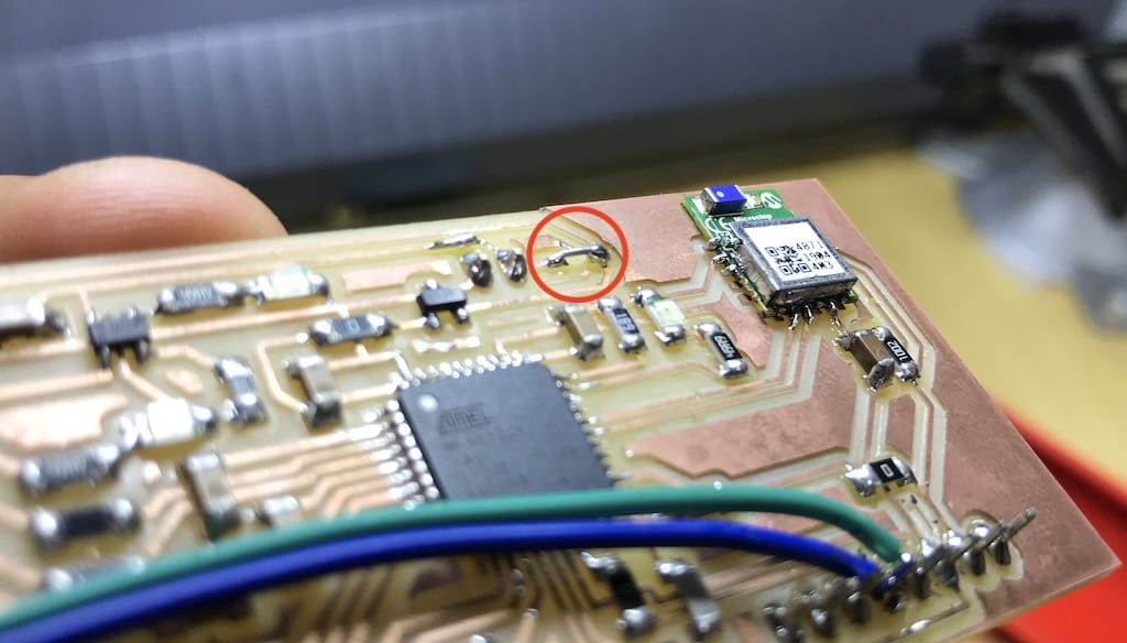
Then, after some inspection, I’ve found that the crystal had the traces together AND I was using an incorrect 20 MHz.
Week 20
Programming
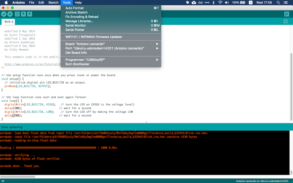
After clearing the path and changing the crystal to a 16 MHz. I was able to identify the board and burn it’s boot-loader.
Then, it showed up as a Arduino Leonardo and I tried uploading code with only the USB.
Next, the battery test.
Battery charger
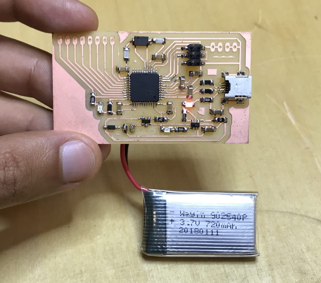
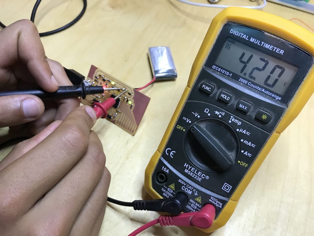
With this working, I checked the voltage everywhere and it looked ok. After, I connected the USB and waited until the battery was charged to see the result.
After 30 min with the USB connected, the status LED from the charger went on, meaning the battery is full.
Just realized the SDA and SCL pins on the board are not connected. Back to drawing.
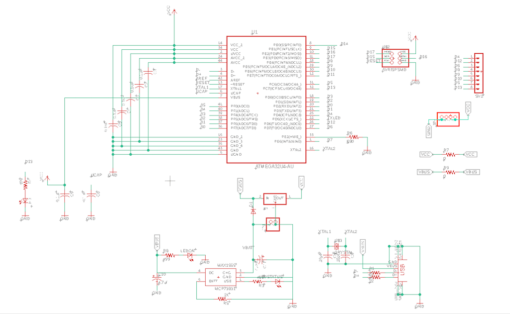
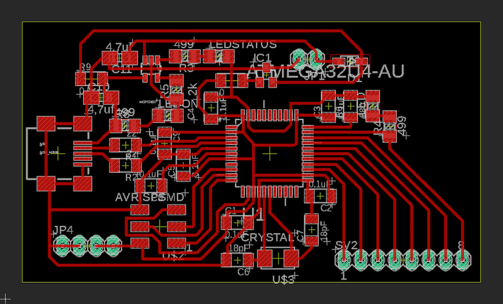
Board v2
In order to fit every thing at the right place, I imported the board drawing and placed the components.
I was supper happy that the board worked on my first try.
But I still needed to remove the RN4871 chip from my other board and connect everything.
One problem I faced after doing that was that the Schottky diode has dropping the voltage from 3.3 to 2.7v hence the display was not showing anything.
After removing it and replacing with this beautiful jumper, it started working. A big note is that now I cannot plug the USB with the battery connected. This needs to be corrected on a future iteration.
The other jumpers were supposed to be traces on the other surface of the board. But since we did not dispose of two layered PCBs at the time. This was my workaround.
Then, after a couple of quick adjustments from the previous test, I set out to print the enclosure and mount again.
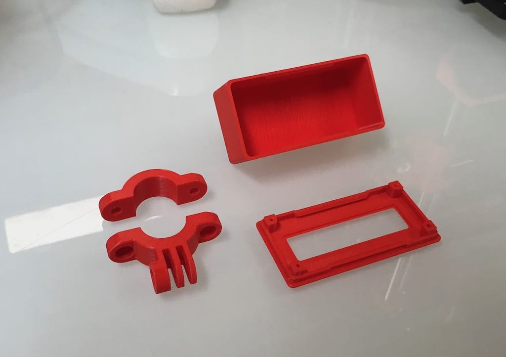
3D printed enclosure
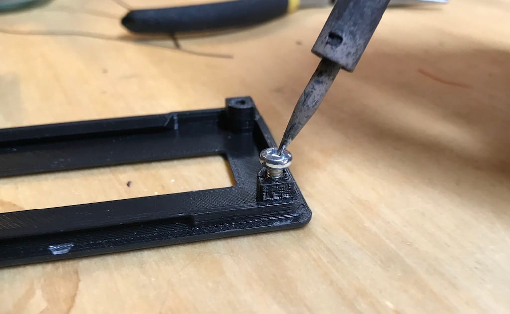
One of the fixes was the mount diameter to better fit my personal bike. And the other, the radius of a corner that did not fit properly and I had to file it.
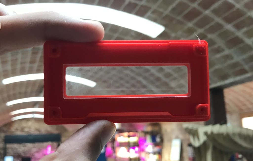
Laser cut acrylic lid
While that was being printed. I made the acrylic cover for the display. That goes into the lid and helps a bit with dust and water getting in.
Then, I wanted to fix the display but couldn’t find the right screws. So I tried heating it with the soldering iron and push it against the plastic. It turned out to work really well. It is just not practical to take it out later, but I believe there will be no need.
Before ruining my newly printed lid. I tried on the old version just to make sure.
With this, I had a solid block that would fit inside the enclosure.
First test
After soldering everything. I was able send messages to the RN4871 module using their app. But could not with my own. There is some kind of configuration missing in order to make it work.
This is strange since it was working before. But a relief is that it is at least working somehow. I read that these modules are not so reliable and have a history if bricking out of nowhere. So I’m hoping that’s not the case.
After a while I realized that the chip is being discovered but only not showing to connect for some reason.
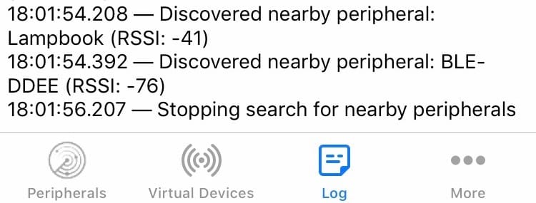
I tried other app and it worked but it is not consistent. Even having a strong RSSI and slow baudrate I ged random characters on the screen. Not helping the purpose of having a device that is not distractive.
Since there is no much time left I’ll set back to using a HC-08 module that has been working since the beginning.
Accelerometer
To change things a little bit, I decided to code the safety feature using the accelerometer.
I’m using a MPU6050 packaged together with other sensors, but it is the only I’ll use for now. I was playing a bit with the raw data but there is a lot of parsing needed in order for it to be useful.
Following this page I managed to calibrate and parse the raw data to something more readable.
There is the option to wire the INT pin to cause interrupts on certain events (E.g. free fall or high G). But this would mean another jumper or a new board.
Board v3
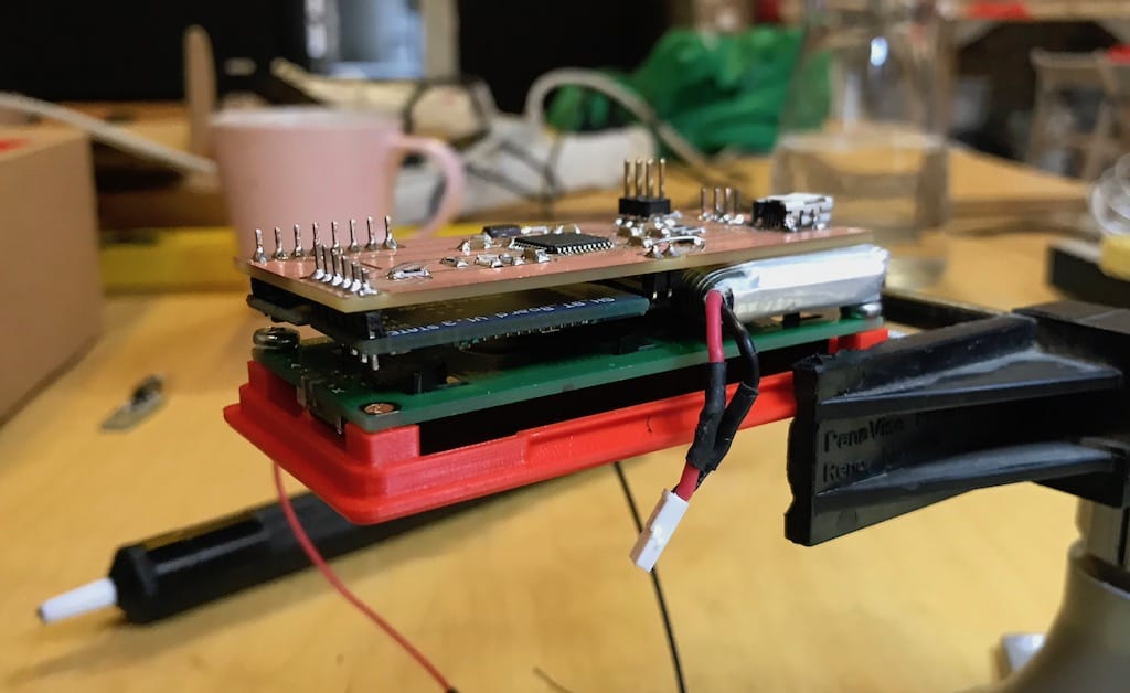
After the two versions and problems, I decided to make another board, simplifying a little and arranging the three boards better.
This is what I came up with.
One neat thing I tried was burning the bootloader without soldering the ISP connector. It took a couple of tried but it worked!
I spent the whole night trying to put everything together at once, on their respective places, and it turned out to be extremely difficult. Having every component soldered together makes a solid build. But it is way harder to debug and adjust anything.
For example, to adjust the display potentiometer I had to unsolder the whole thing apart.
But, then I decided to wire everything with jumpers and make sure it worked 100% before assembling it back together.
This turned out to save me a lot of time (after wasting a bunch), and it worked really well.
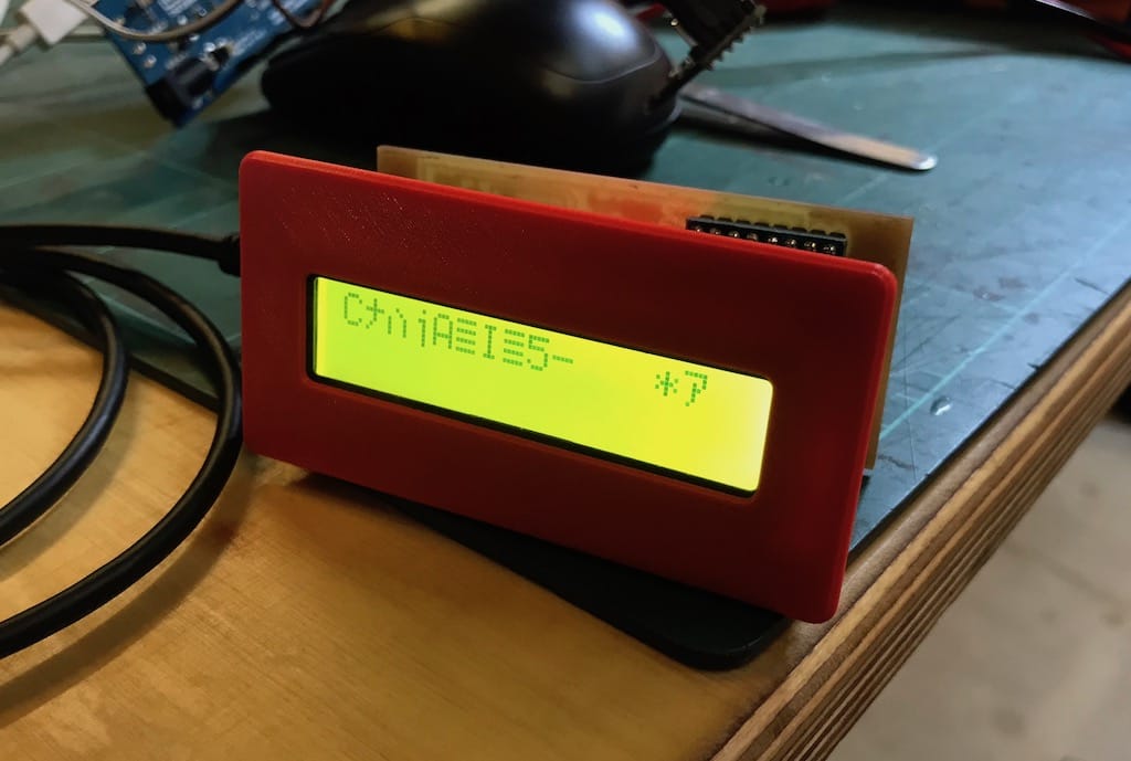
After getting the basic system working again. I decided to tweak the code a little bit, center the text and add a “You have arrived” message.
Then, it was time to put it back together. It is more difficult than I thought.
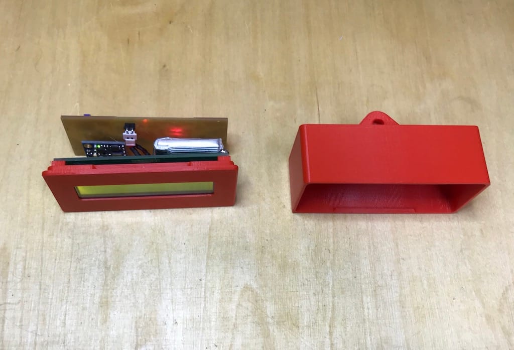
I needed to extend the power cables to go all the way around the device. But it turned out nice.
The enclosure and mount work are pretty straight forward. Just screw the holder onto your handlebar.
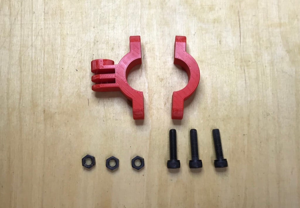
Then, screw the enclosure to the mount and you’re good to go!
Demo: