7. Electronics Design
assignments
group project:
- use the test equipment in your lab to observe the operation of a microcontroller circuit board
individual project:
- redraw the echo hello-world board, add (at least) a button and LED (with current-limiting resistor) check the design rules, make it, and test it
- extra credit: simulate its operation
Group project
We’re still going to have an oscilloscope class. So for now, we will test our own boards with the multimeter.
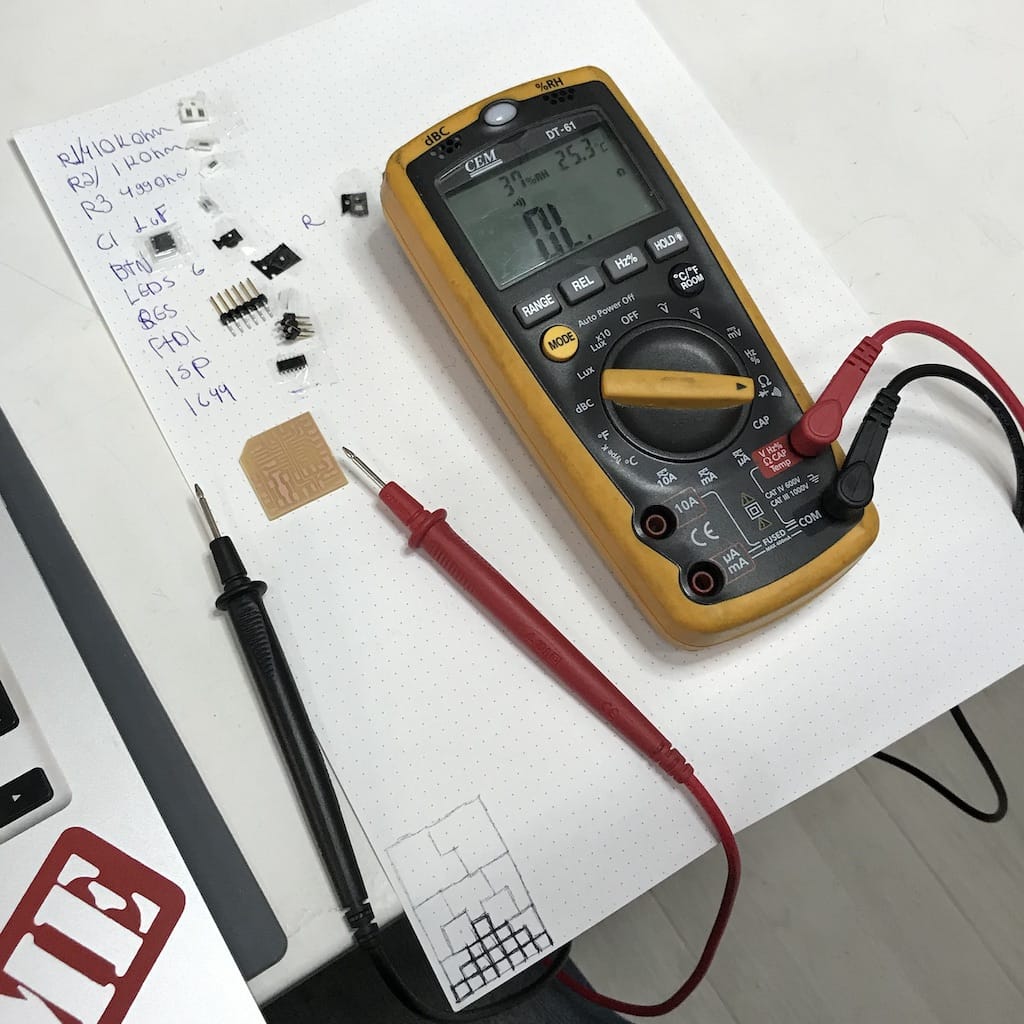
First, we checked the boards continuity before and after soldering. Everything looking good.
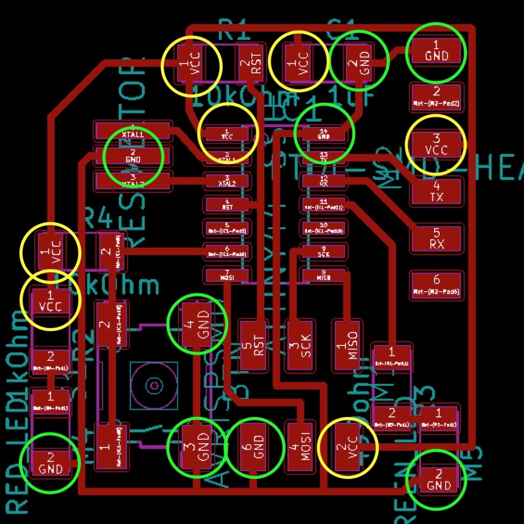
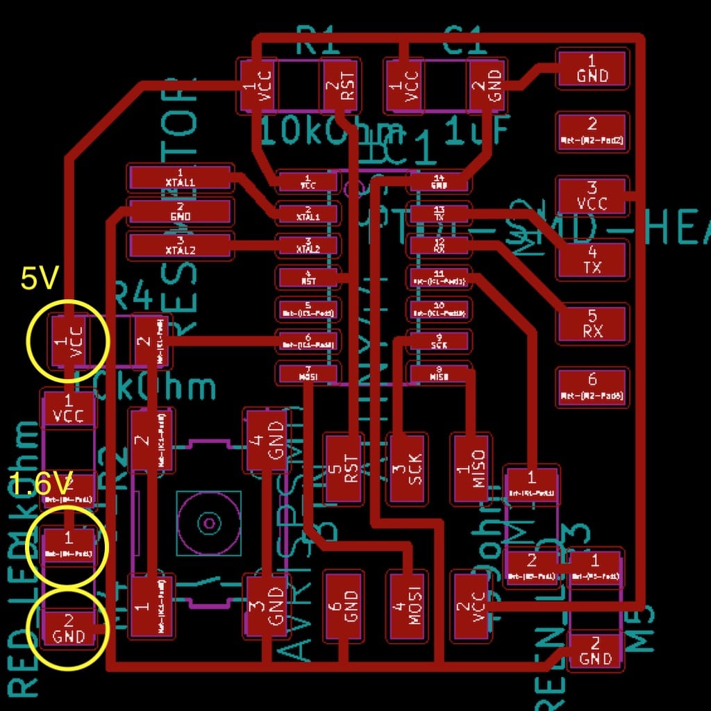
Then, voltage powering the LED, before and after the resistor.
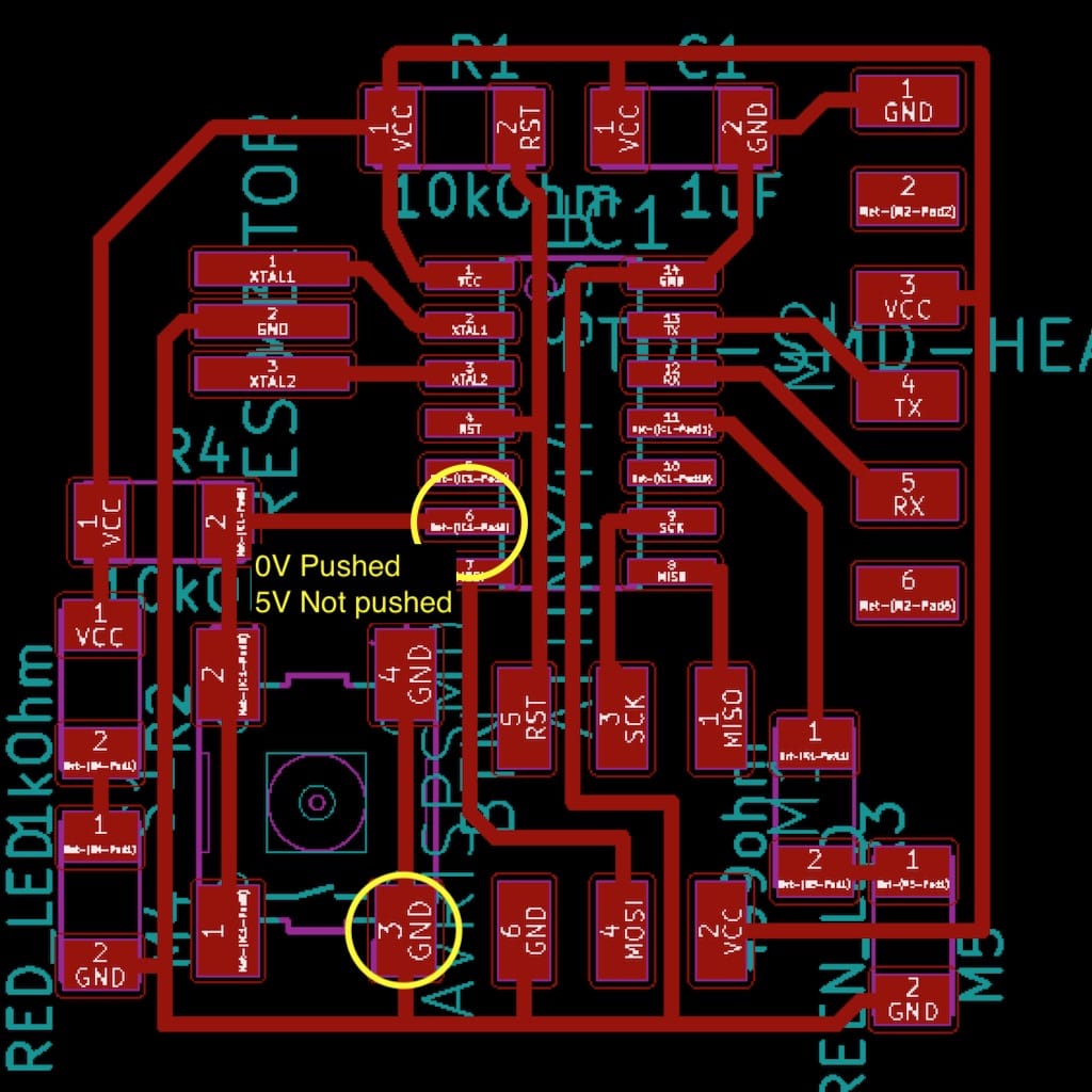
Understanding the button state is really easy when you measure the voltage on the IC port.
Will update as soon as we start using the oscilloscope to test the board.
Individual project
Eagle class
We had a nice tutorial on Eagle, showing the whole process of drawing the schematics, routing the board and then exporting to make it.
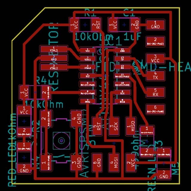
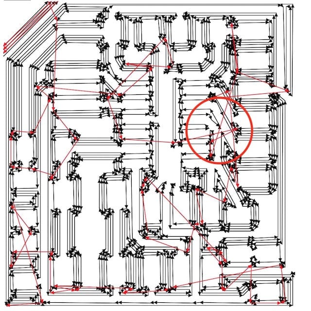
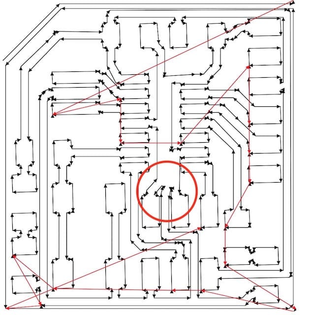
After routing the puzzle, got to this result.
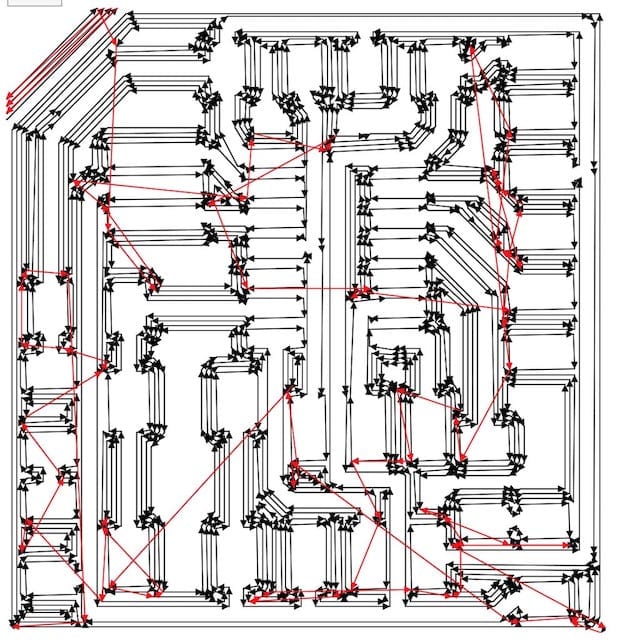
But, the trails were really close to the connectors, and I’d probably have problems when milling or soldering. So I added a little bit more clearance.
![]()
Then, I could export it as traces and cut files.

But, as soon as I imported it to mods I realized the board was too big.
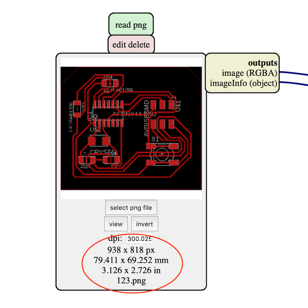
After a couple of minutes of research, turns out this is a known bug without solution so far, other than paying attention to the actual size during the export and then resizing the image.
I was already tired but wanted to mill the PCB and test it. But then a colleague noticed we were missing the FTDI connector. Then I called it a day.
KiCad class
Since I’m trying to use open source whenever I can, I really wanted to learn KiCAD and took a class here on the fab lab.
This is the basic workflow:
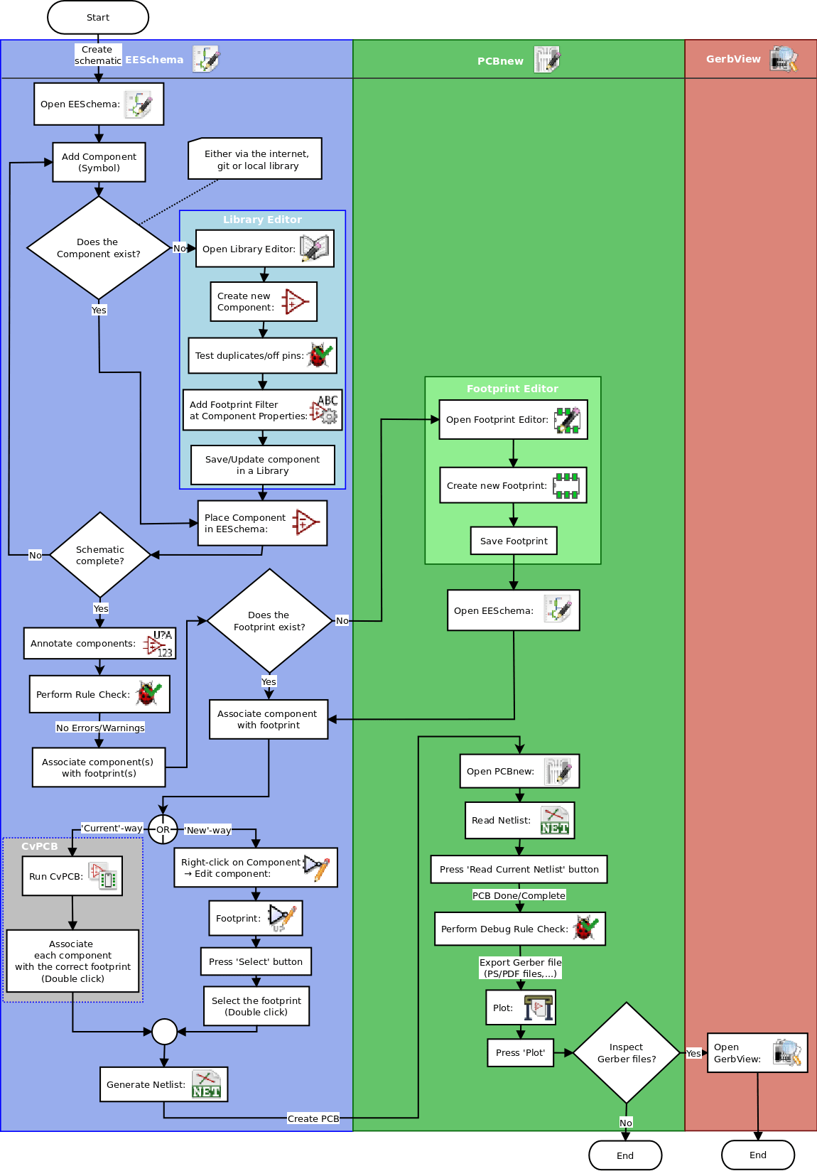
So after adding the schematics and footprint libs, I was able to start drawing the schematics. I decided following the board example from the assignment, but already added a LED just to know it the board was being powered correctly.
Then, the flow on KiCad is to create a netlist to be able to open import the work to the board editor. Named pcbnew.
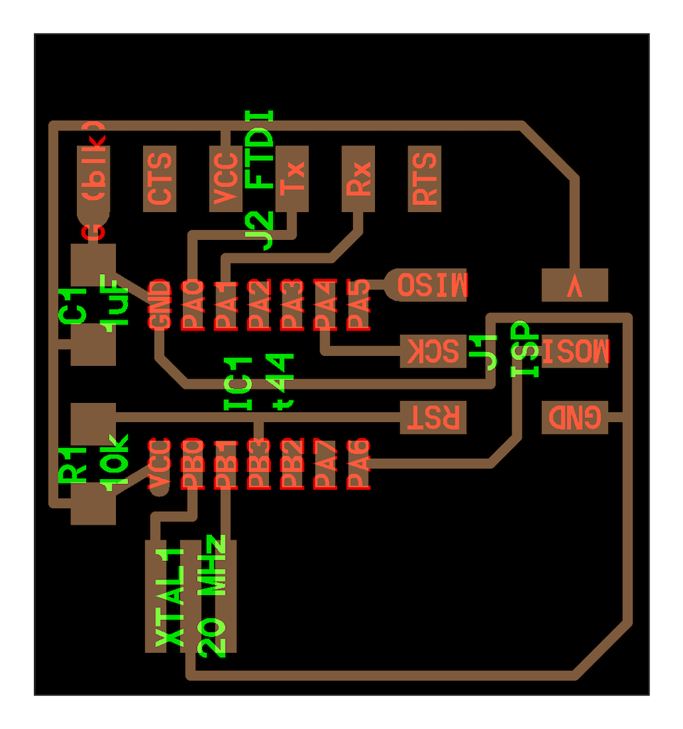
Once inside pcbnew, you should set the design rules and start routing. I followed the assignment layout so it would look similar
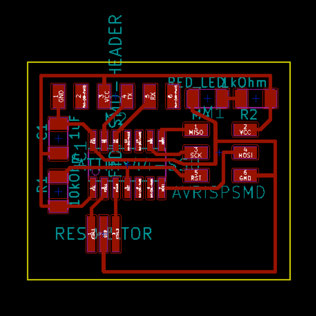
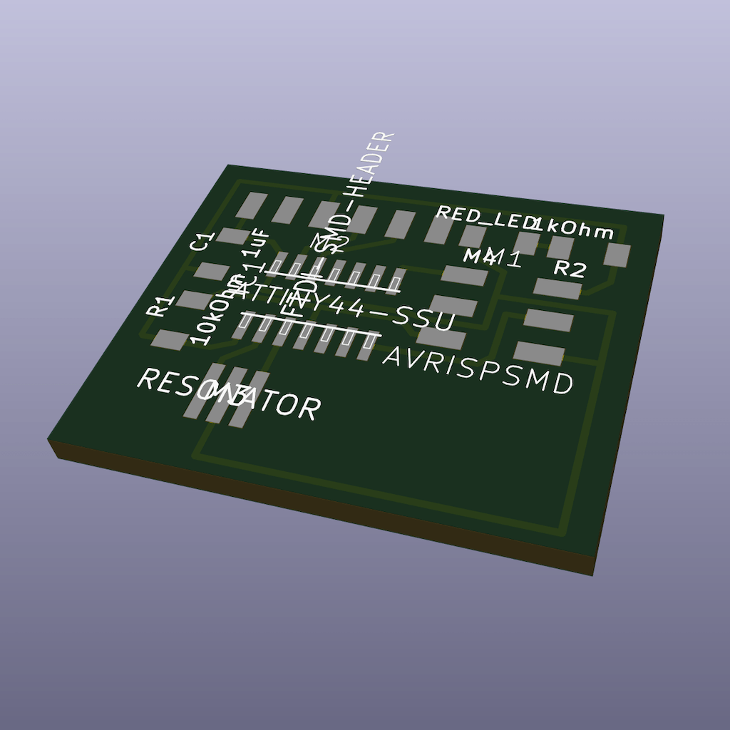
A great tool is visualizing the 3D view of your board. But our lib doesn’t have the components. The lab will update so we can use it better.
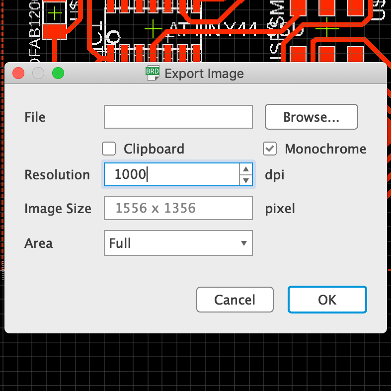
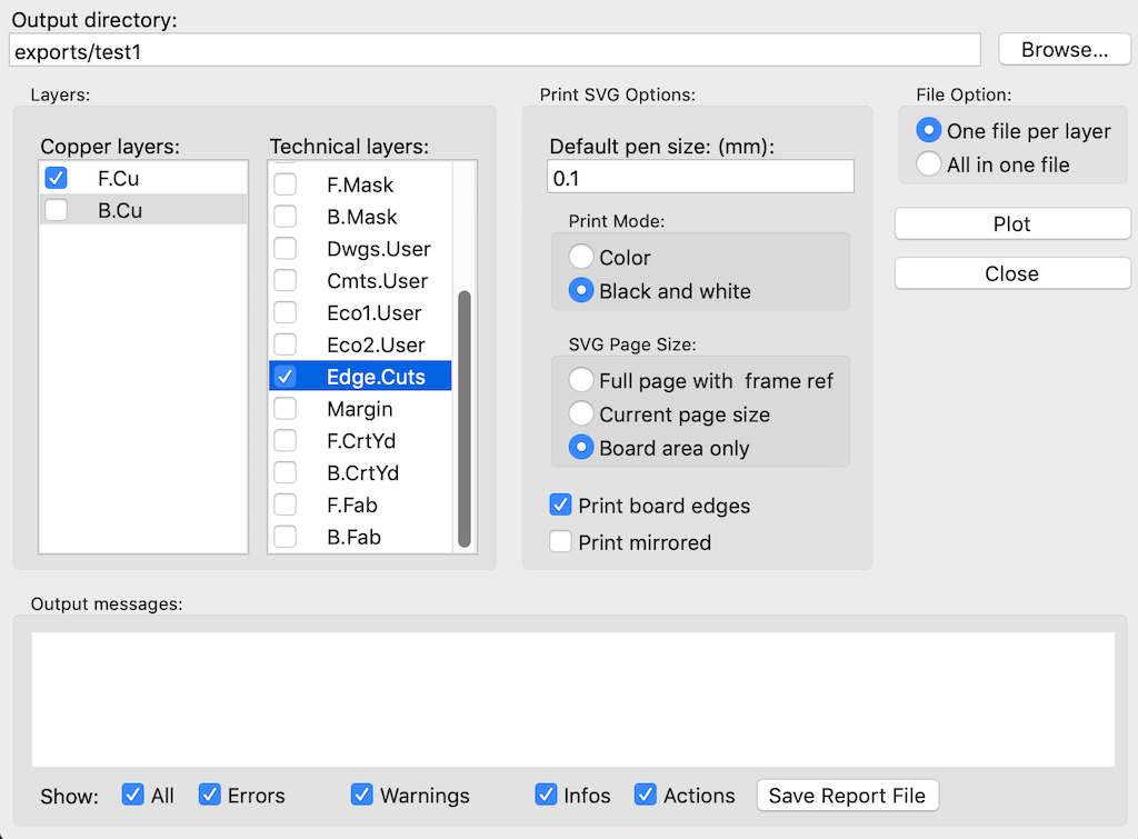
The export to svg works well
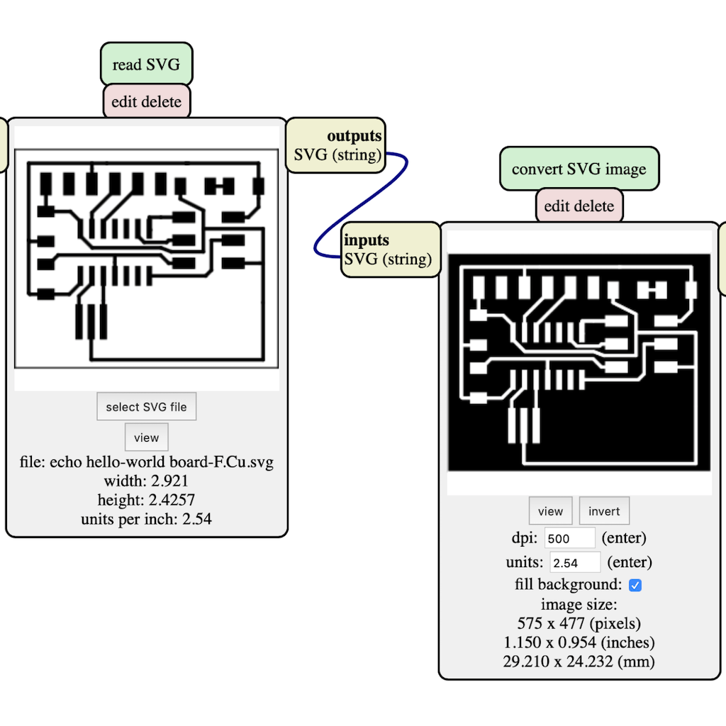
And mods does the rest of the job
After taking the class, I was sure I’d stick with KiCad over Eagle, at least for now.
Designing the board
So far, I’m still trying to connect all the fragments of knowledge I have in electronics to understand how things work. So it is still difficult to plan ahead or even know that I have to do.
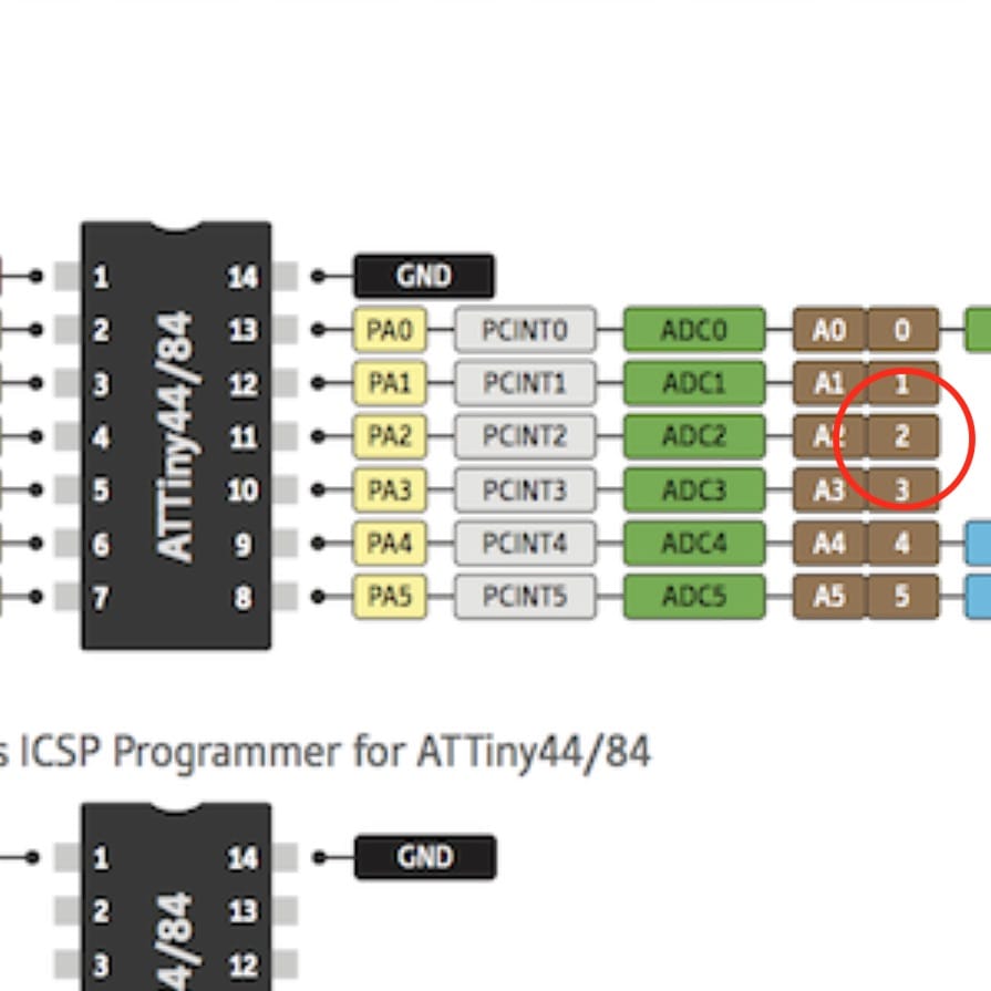
First step is to check the IC datasheet.
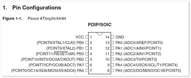
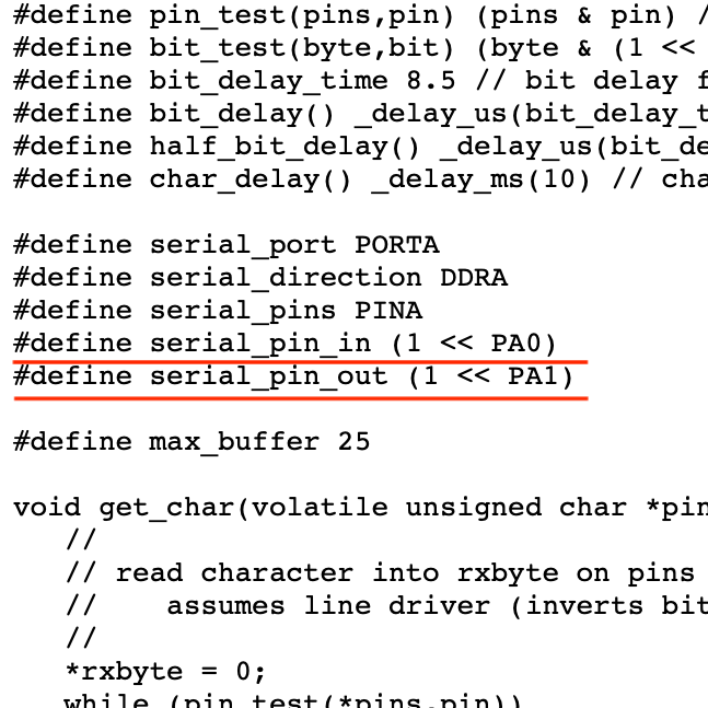
The datasheets are overwhelming, specially if you don’t know what to look for. But one thing I figured is to check if there is any hardware serial ports or if you can just use any. Attiny44 doesn’t seem to have, but on the program code the ports PA0 and PA01 were designated. So I’ll stick with it so I don’t have to change the code for now.
From there, you should look the recommended instructions for every part you want to add. To make sure they’re optimized.
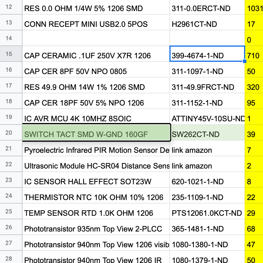
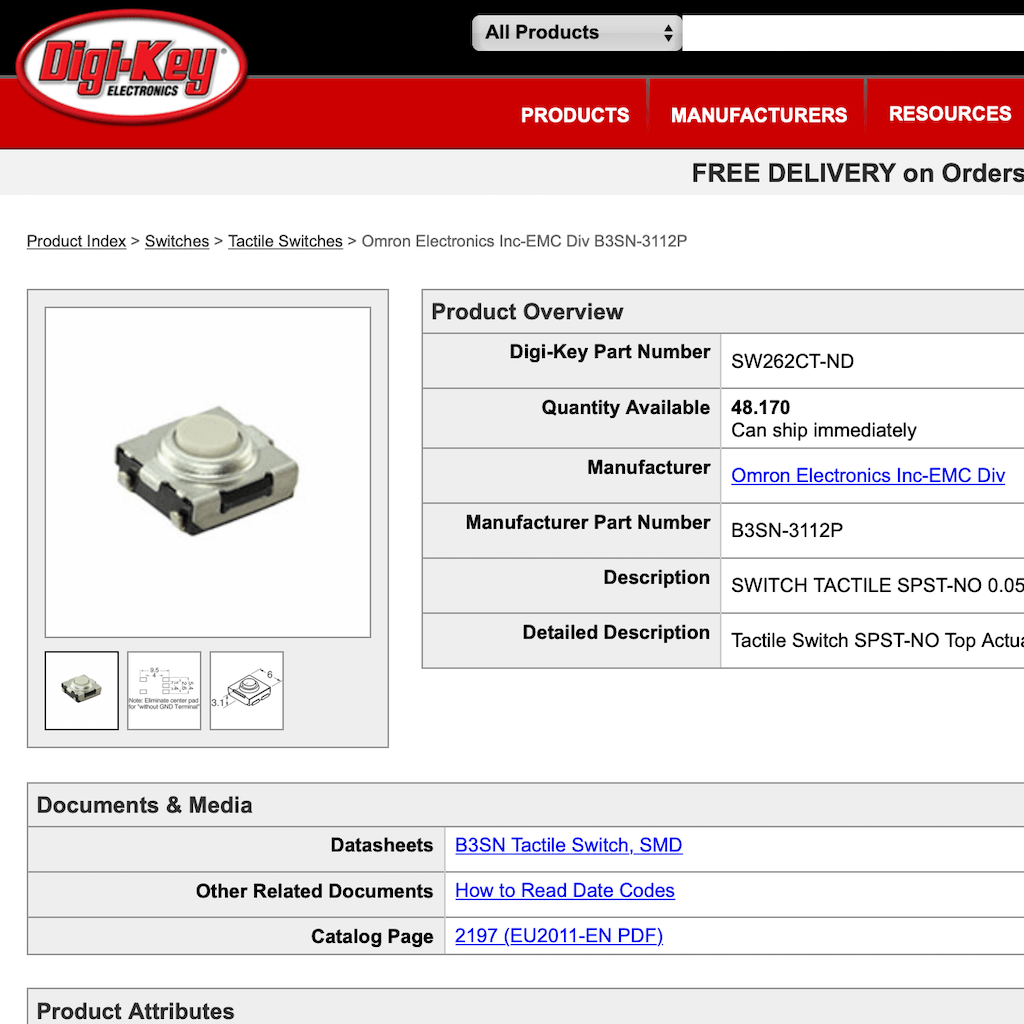
Here on Fab Lab Barcelona we have a spreadsheet with the components available. From there, we can take the part code and look the vendor website for the specs.
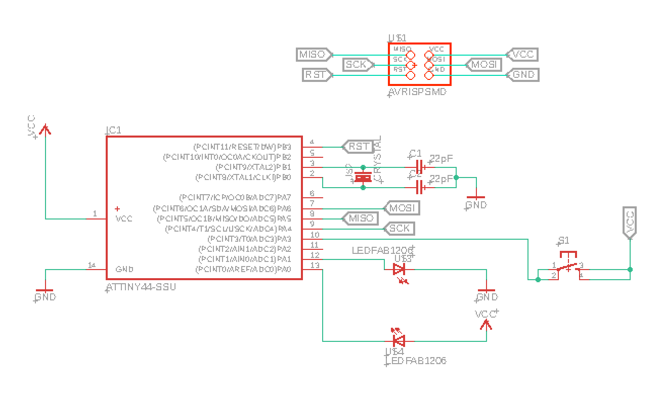
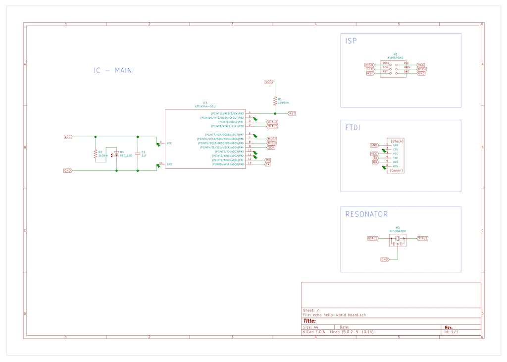
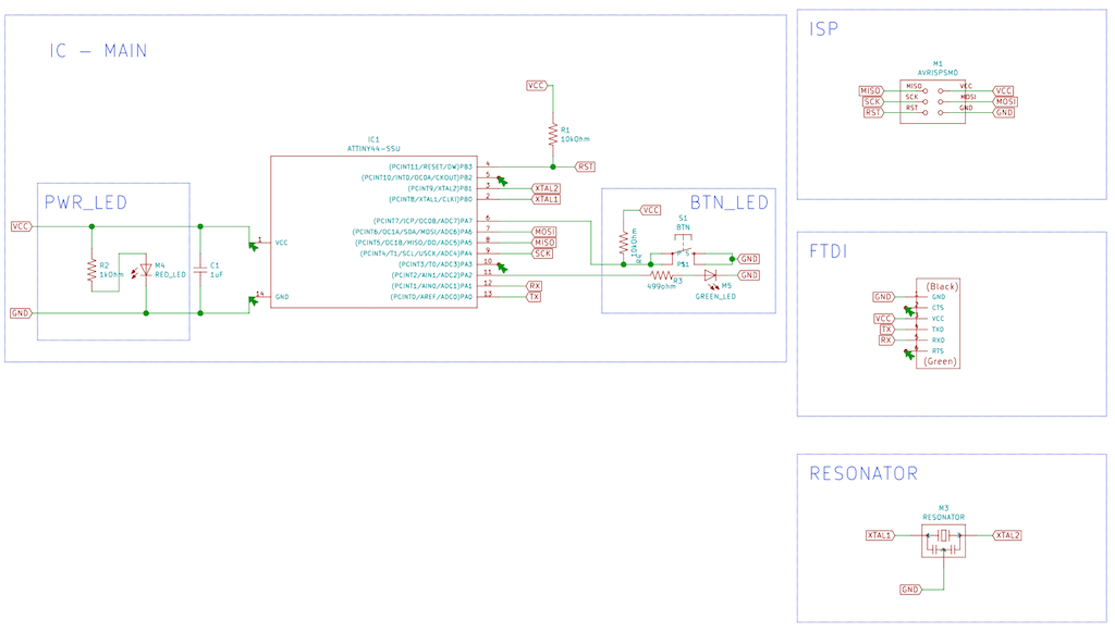
After checking everything, got to this schematic.
And then, the journey of routing began. I had to iterate through 4 versions to get it all right. But know I believe I have the right rules for designing.
Design rules

V1
V2
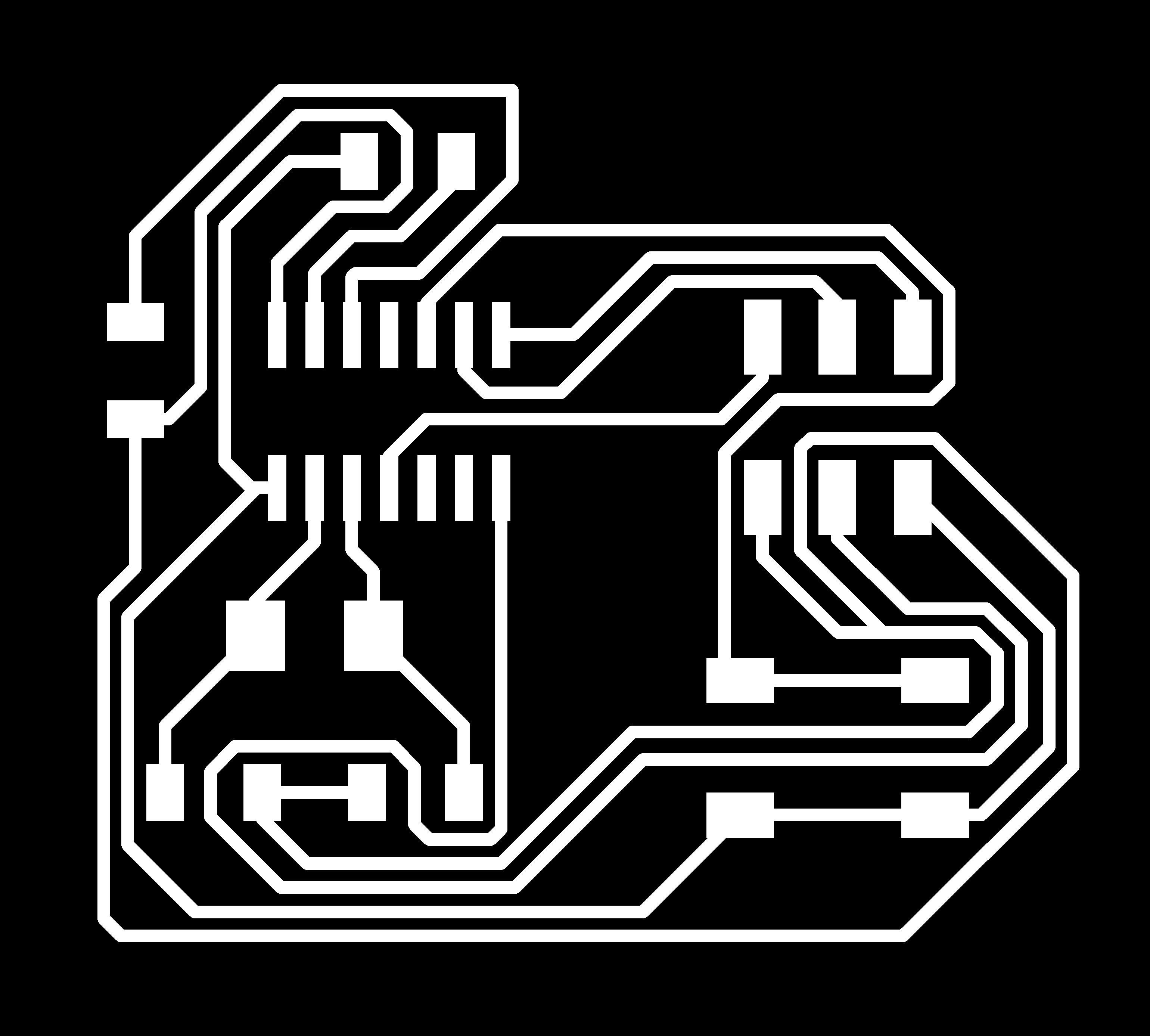
Milling the board
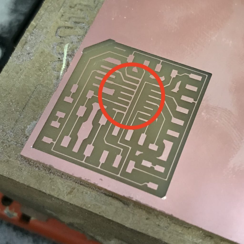
The first and second version had visible errors when looking at the mods file, but the third seemed ok. So I decided to mill it. But for some reason, the trail and connectors of the IC stayed together.
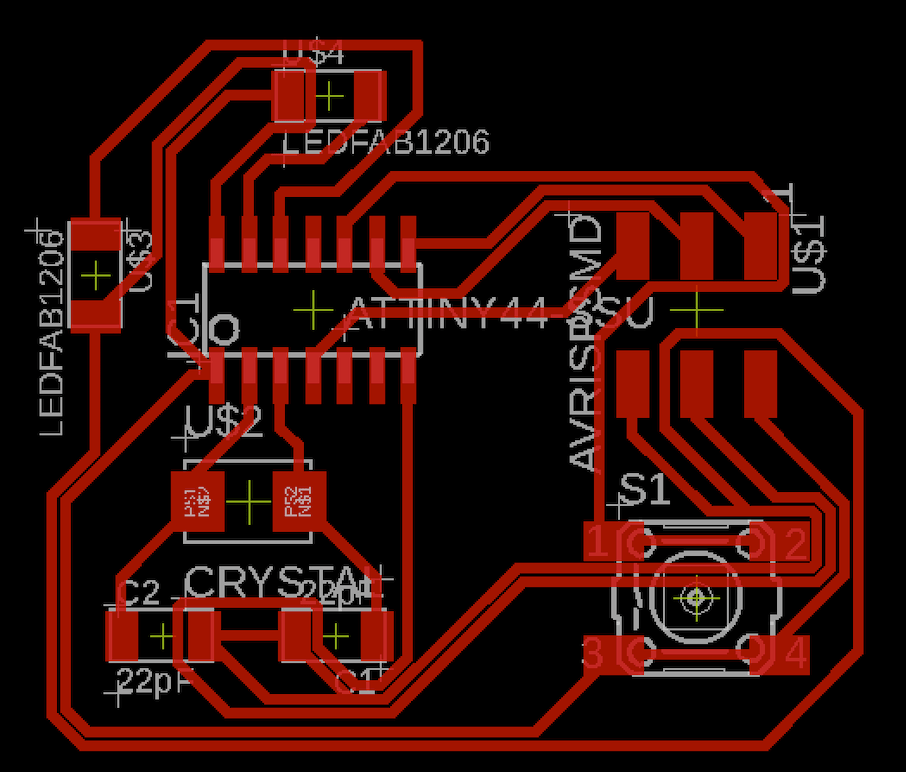
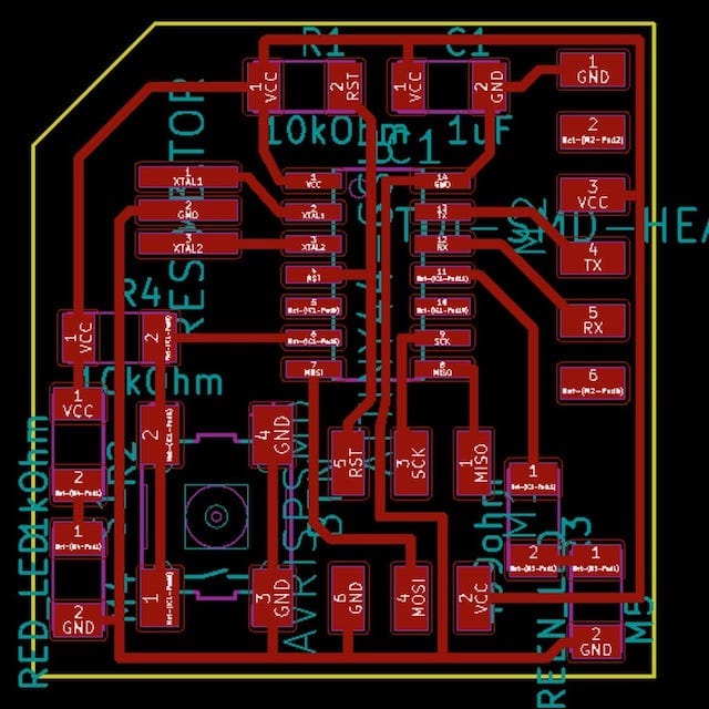
V3
I thought the board looked too tiny, but checked with a component and it seemed ok. So I ran the version 4 and it turned out good.
V4
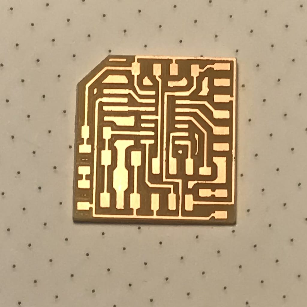
Now I got to the desired result. It will be a challenge to solder such a small board. But I guess it will be a nice exercise.
Download V4 SVGs Download V4 KiCad files
Soldering
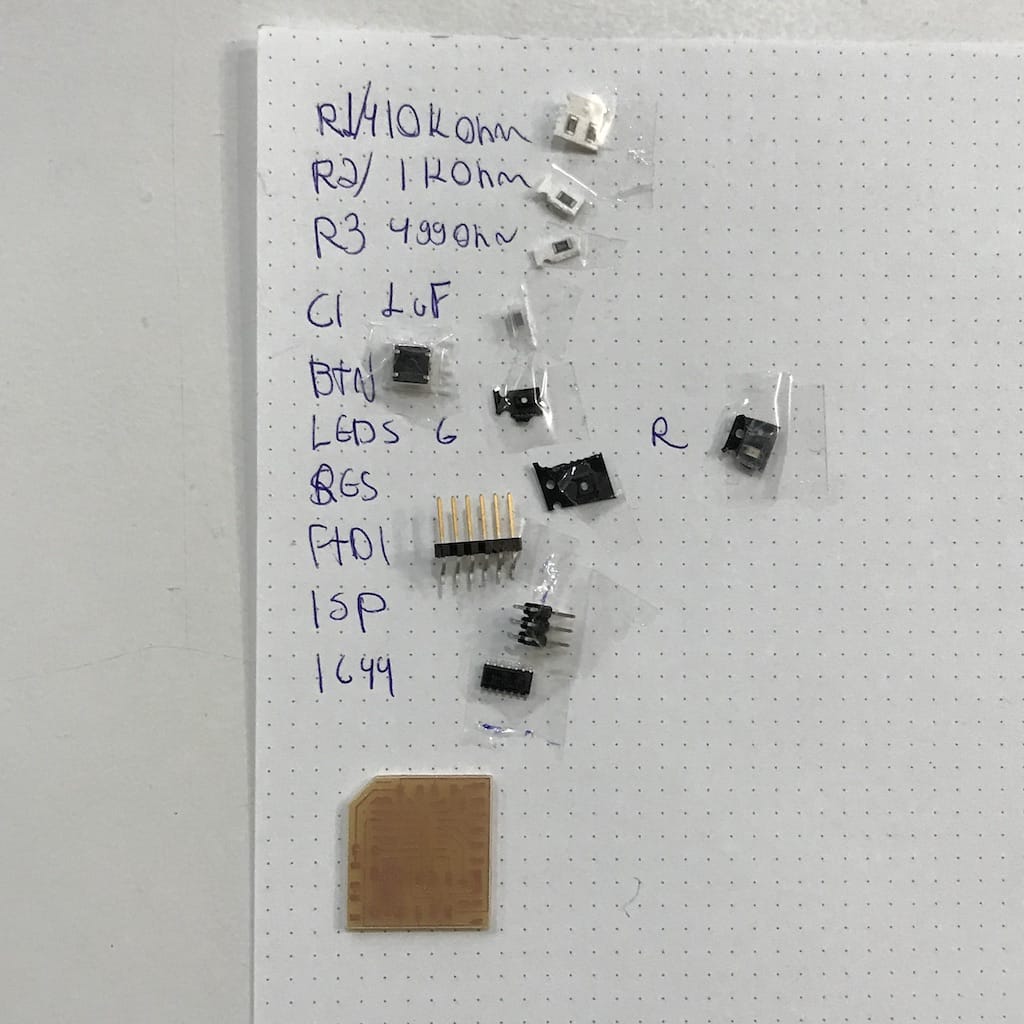
Time to get the components and get to work.
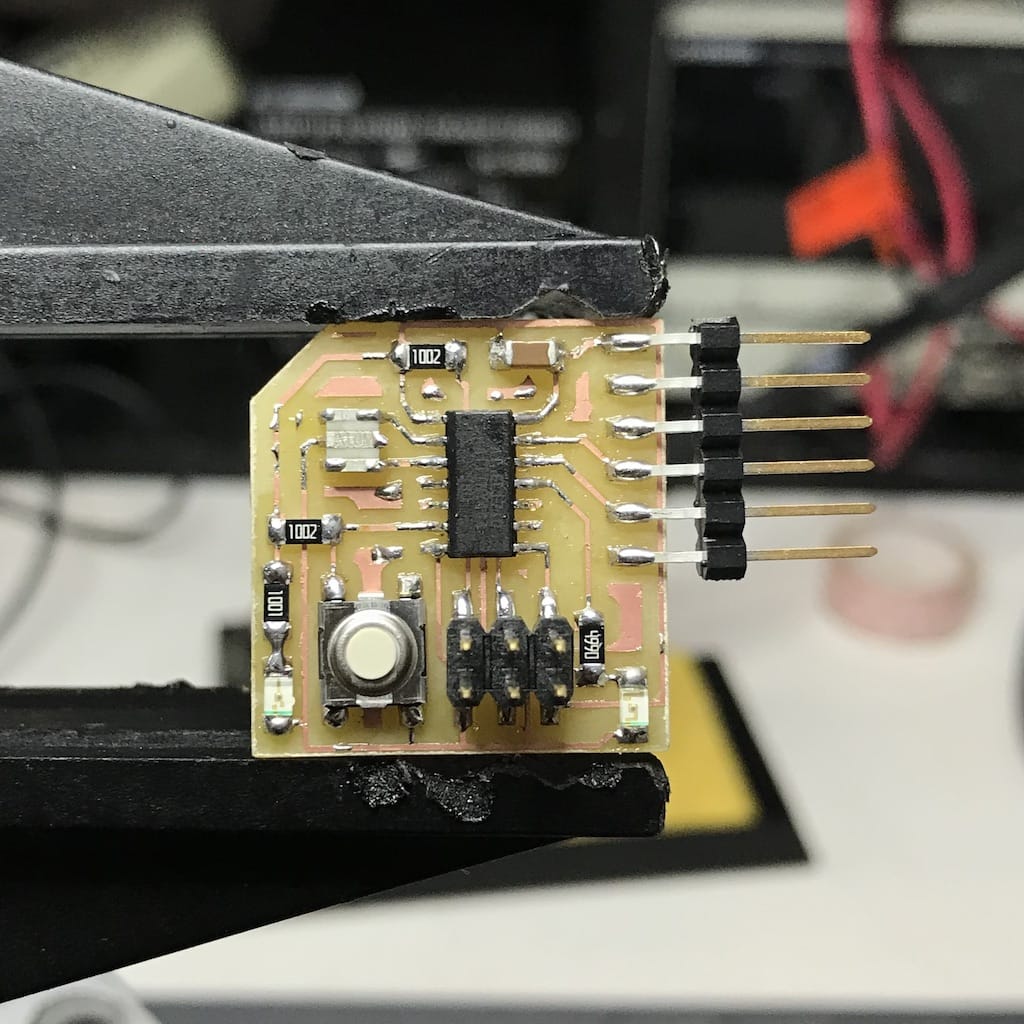
After an hour (had some shaking hands today), god everything soldered and looking nice.
Programming
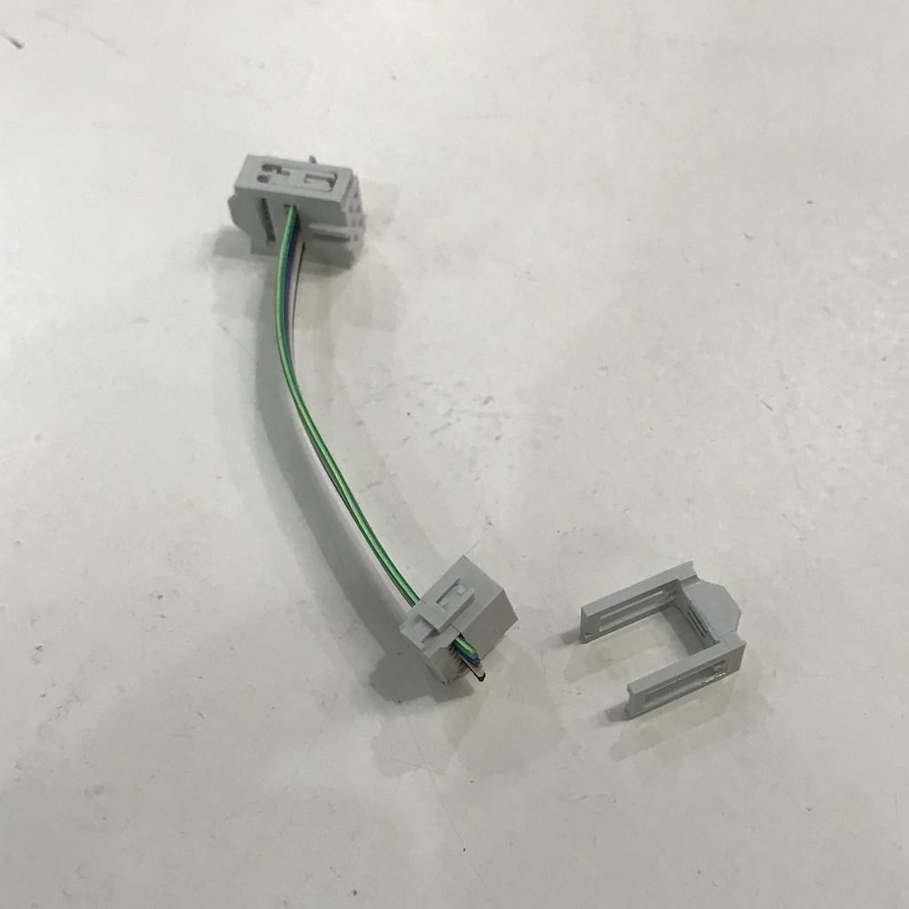
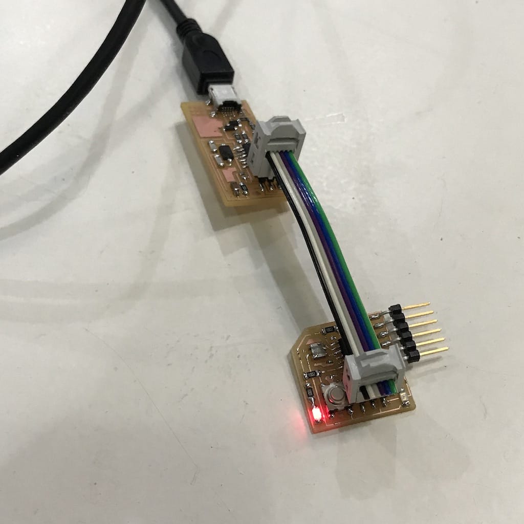
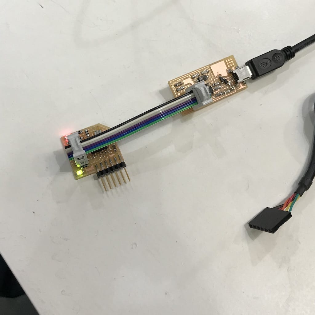
First step was to make a ribbon cable for the ISP connectors.
I wanted to make sure I was connecting the cable using the right orientation, so I opened both boards diagram.
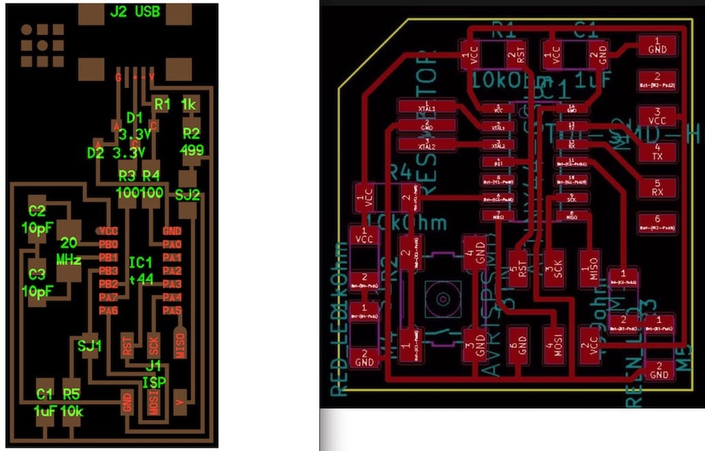
After making sure, connected to the computer and the PWR LED turned on as expected. Then I waited a few seconds to check if the board would go hot or the computer would give any errors. But everything seemed fine.
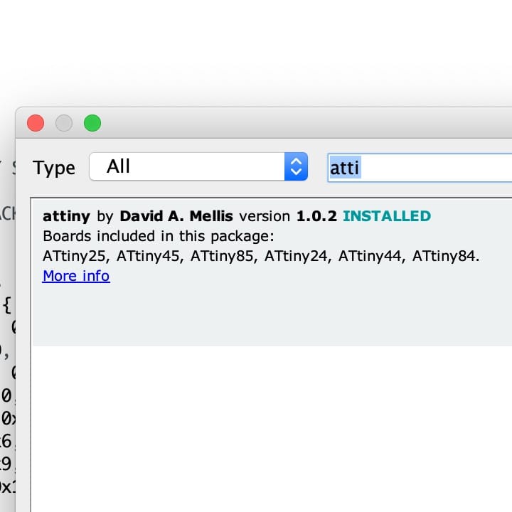
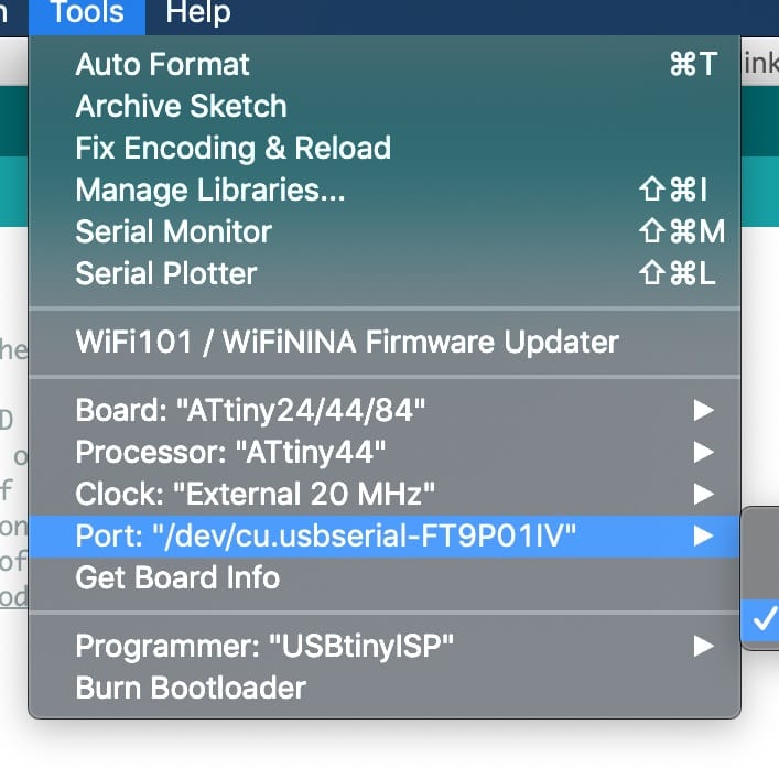
Then, had to add the ATTiny library to arduino IDE, configure it to communicate with the board and then burn the bootloader.
Blink
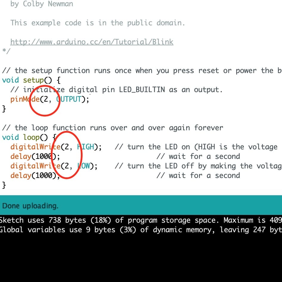
After that, uploaded a blink example to test the board. Had only to assign the right pin output number. Checking the ATTiny44 documentation.
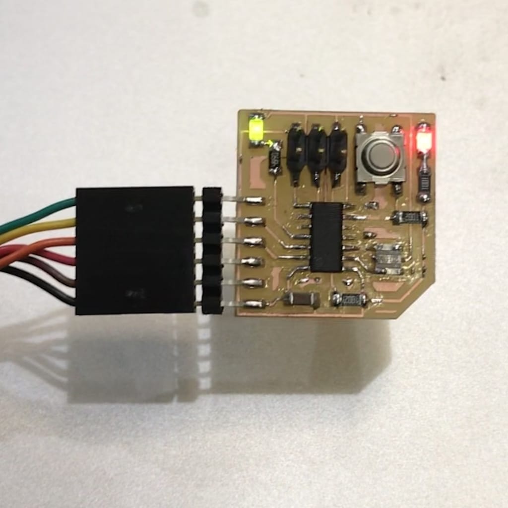
The board works, but I wanted to check if it was working with the FTDI cable as well. And it does!
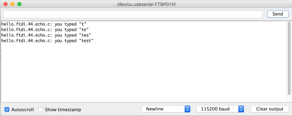
Echo
Tried uploading the echo code directly through arduino IDE and the programmer. It seems to be working fine.
My own code
Tried to test the button as well
#include <SoftwareSerial.h>
int incomingByte = 0;
SoftwareSerial mySerial(0,1);
int pushButton = 7;
void setup() {
    mySerial.begin(115200);
    pinMode(pushButton, INPUT);
}

void loop() {
  int buttonState = digitalRead(pushButton);
  if (buttonState == 0)
  {
    mySerial.println("button pushed");
  }

}
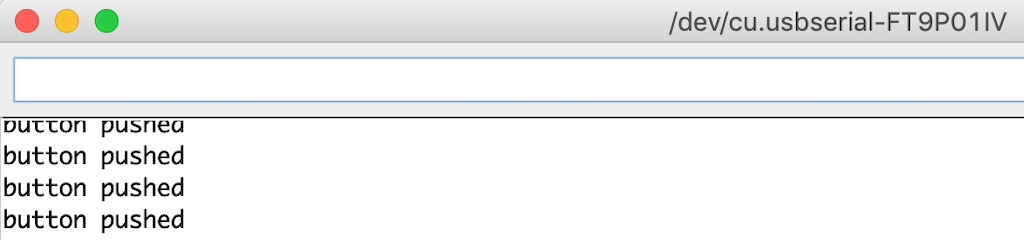
Everything seems to be working fine. But my goal is to create a program that uses all the functions at the same time. Will update this page as soon as I make it. So far, I’m changing the state of the LED and printing it in the serial.
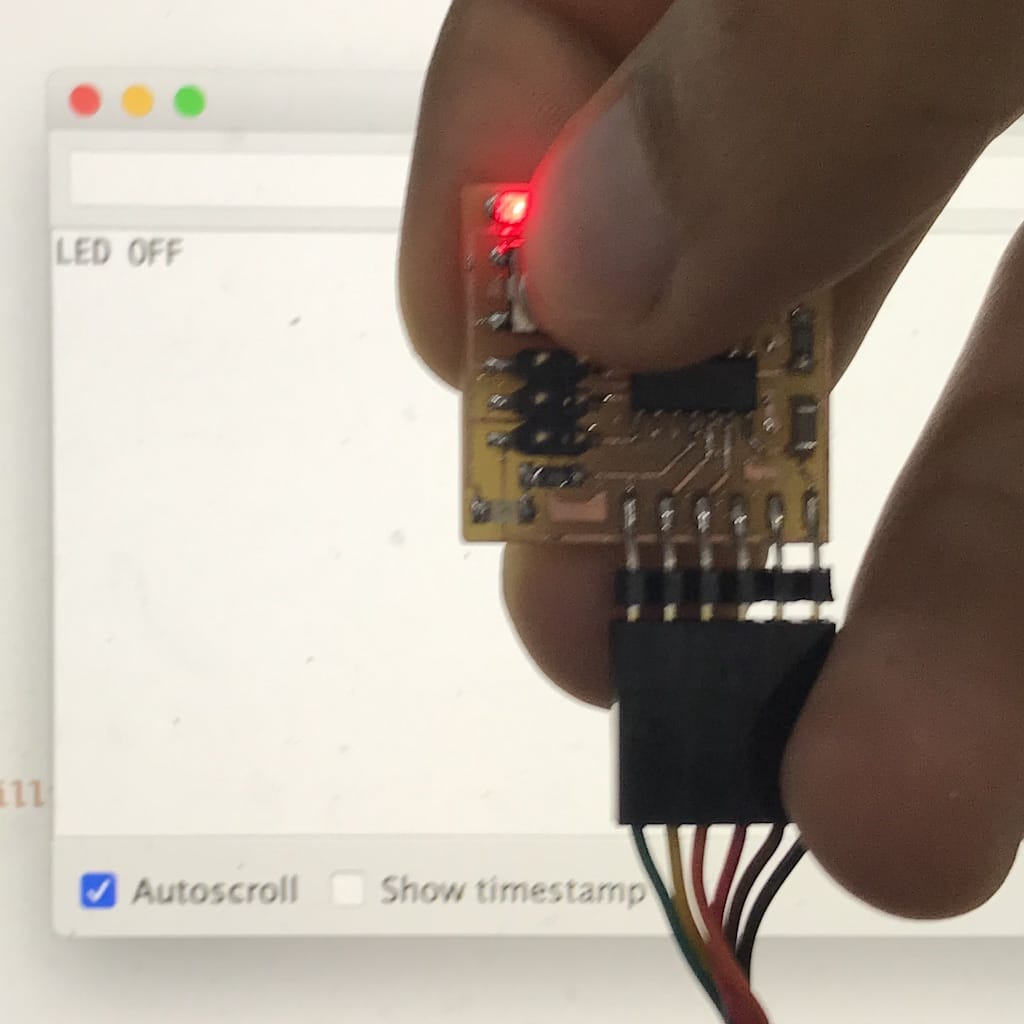
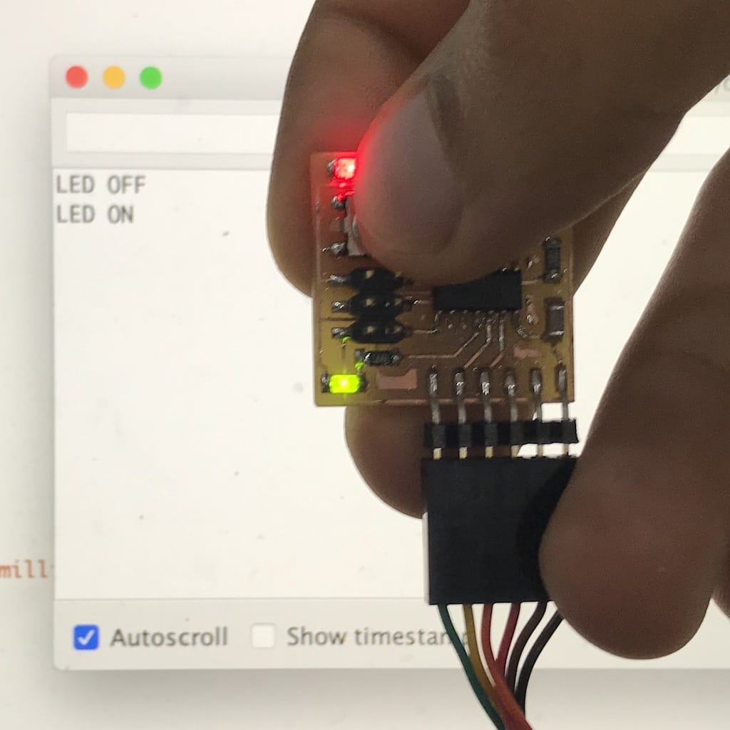
#include <SoftwareSerial.h>

SoftwareSerial Serial(0, 1);
int pushButton = 7;
int LED = 2;
int stateLED = LOW;
int stateButton;
int previous = HIGH;
long time = 0;
long debounce = 200;

void setup() {
  pinMode(pushButton, INPUT);
  pinMode(LED, OUTPUT);
  Serial.begin(115200);
}

void loop() {

  stateButton = digitalRead(pushButton);
  if (stateButton == LOW && previous == HIGH && millis() - time > debounce) {
    if (stateLED == HIGH) {
      stateLED = LOW;
      Serial.println("LED OFF");
    } else {
      stateLED = HIGH;
      Serial.println("LED ON");
    }
    time = millis();
  }
  digitalWrite(LED, stateLED);
  previous == stateButton;

}
Part of this code comes from this tutorial on retaining the LED state, and the Arduino serial example