9. Embedded Programming
assignments
individual assignment:
- read a microcontroller data sheet
- program your board to do something, with as many different programming languages and programming environments as possible
group assignment:
- compare the performance and development workflows for other architectures
Since I’ve already programmed my board on week 7, I’m going to try different boards, languages and environments. But my goal is to understand more how MCUs work and really get started on programming my final project. So part of this week’s documentation will be posted on my final project development page as well.
Understanding the AVR microcontrollers (ATtiny44)
Resources
4K Bytes of flash program memory
256 Bytes of EEPROM
256 Bytes of SRAM
12 I/O lines
Pins
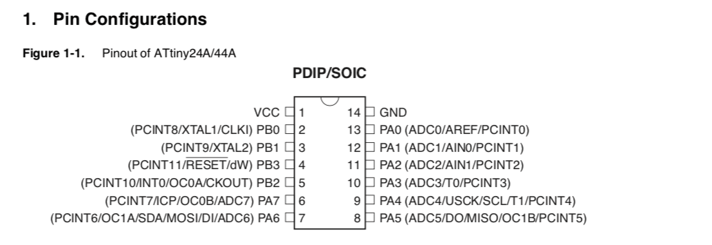
Description:
VCC - Supply voltage
GND - Ground
PB0..2 - 4-bit I/O port
PA0..7 - 8-bit I/O port
PA and PB have internal pull-up resistors
This week I chose to focus more on the AVR MCUs, mainly because it is what’s most available for us to use and I believe it is a good starting point.
I tried reading the datasheet directly, but since I don’t know much, going through those acronyms is really discouraging. So I chose to go one step higher for now.
A good start was the Fab Academy tutorials for this week:
Attiny44 fuses
I’ll try to resume and explaining briefly what each fuse do:
- CKDIV8 - Divides the clock frequency by a defined factor
- CKOUT - Use the chip clock as a clock source to drive other circuits, PIN B2 will output the clock.
- SUT - Amount of time to keep the MCU in reset before the external clock stabilizes.
- CKSEL - Set the clock source
- RSTDISBL - Use reset pin as I/O
- DWEN - Enables debug mode
- SPIEN - Enables serial program and data downloading
- WDTON - Enables a watchdog
- EESAVE - Preserve EEPROM memory through chip erase
- BODLEVEL - Turns MCU off if voltage is below threshold
- SELDPRGEN - Allows to upload a program to the MCU by itself
This is the default and hello board fuses:
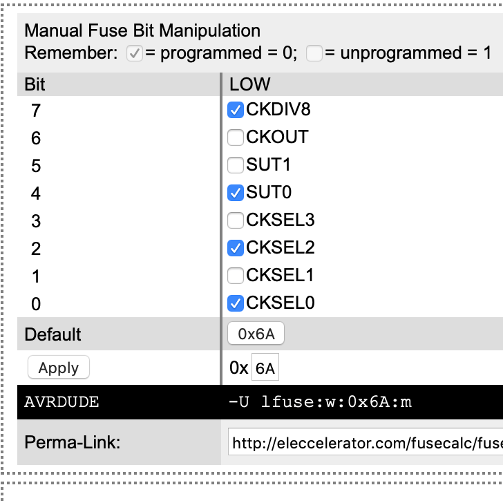

The changes were:
SUT - From 14CK + 64 ms to 14CK + 4 ms Fast rising power
CKSEL - From internal 8Mhz to external 20Mhz clock
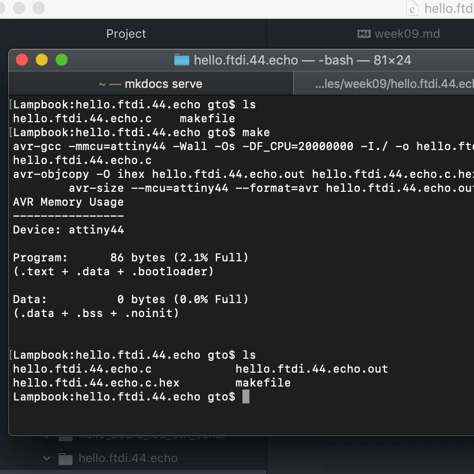
Make and makefiles
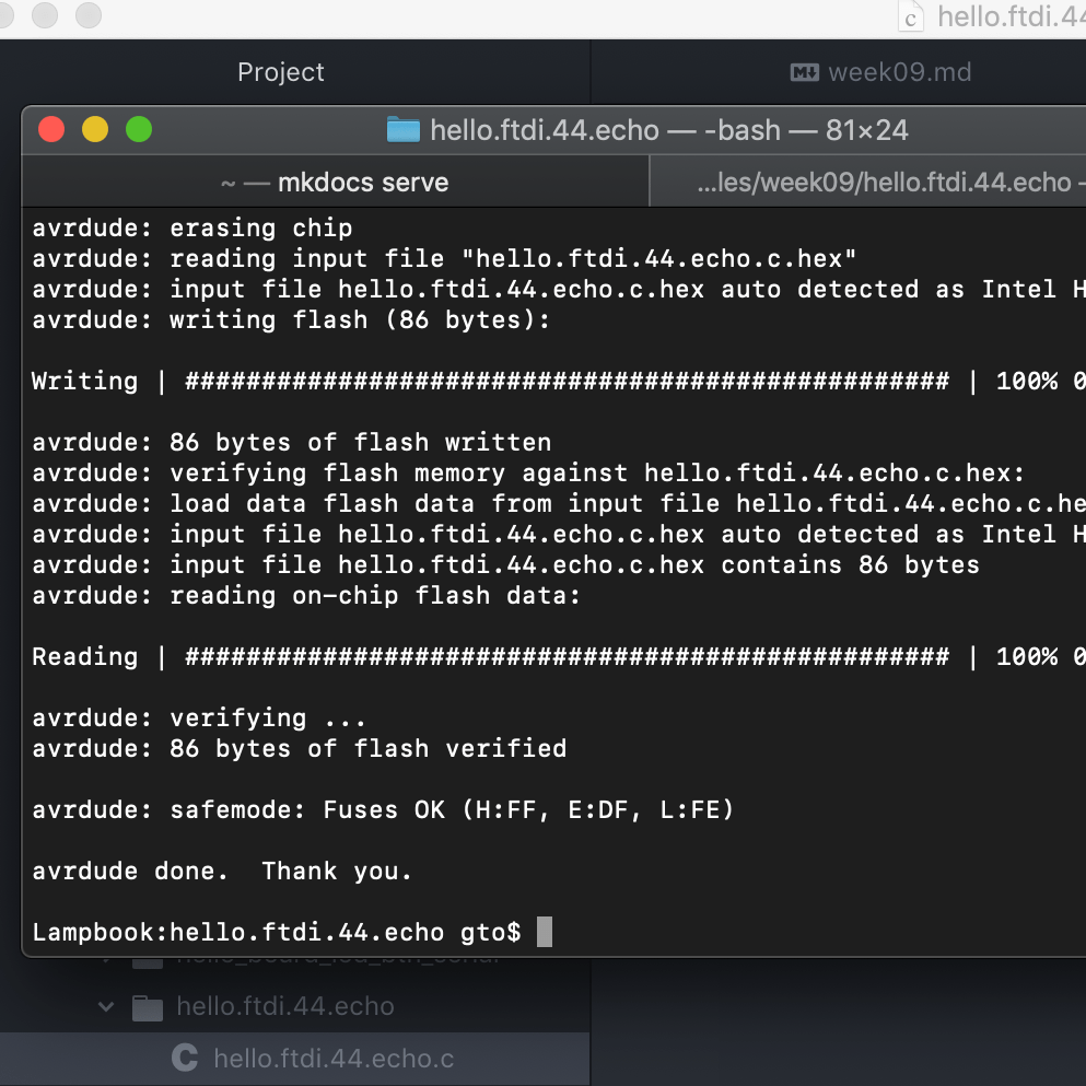
I have tested Neil’s echo hello c code before, but used arduino IDE to upload it to the board. Now, I tried using a makefile and the terminal. I got a couple of unknown errors. After changing the usb port and erasing everything and doing it again, it started working.
make
avrdude -p t44 -P usb -c usbtiny -U flash:w:hello.ftdi.44.echo.c.hex
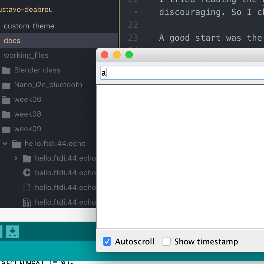
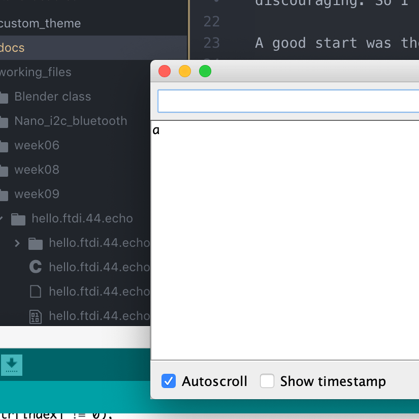
Then, I wanted to simplify the code to just print back what you typed, without the buffer.
while (1) {
   get_char(&serial_pins, serial_pin_in, &chr);
   put_char(&serial_port, serial_pin_out, chr);
   }
Timing an AVR
Started with the tutorial regular example of making a LED blink with C
#include <avr/io.h>

#include <util/delay.h>

int main (void) {
  DDRA |= (1 << PA2); // set LED pin as output
  while(1) { // main loop
    PORTA ^= (1 << PA2); // toggle the LED
    _delay_ms(2000); // wait a second
  }
}
By now, I’m really comfortable with using make and avrdude to program the board. It was something that scared me a bit before this week.
Then, it explained how to use the internal timers and thresholds to have something done without interrupting the execution of the main program.
#include <avr/io.h>
  #include <avr/interrupt.h> // notice that we have swapped libraries, from delay to interrupt

  int main (void) {
    DDRA |= (1 << PA2); // set LED pin as output
    TCCR1B |= (1 << WGM12); // configure timer1 for CTC mode
    TIMSK1 |= (1 << OCIE1A); // enable the CTC interrupt
    sei(); // enable global interrupts
    OCR1A   = 19531; // set the CTC compare value
    TCCR1B |= ((1 << CS10) | (1 << CS12)); // start the timer   at 20MHz/1024
    while(1) { // main loop - do anything you like here!
    }
  }

  ISR(TIM1_COMPA_vect) { // this function is called every time the timer reaches the threshold we set
    PORTA ^= (1 << PA2); // toggle the LED
  }
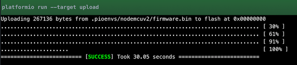
PlataformIO
We had a class showing PlataformIO a good scalable alternative to Arduino. That is able to work with many boards, and integrates beautifully to Atom, that is the text editor I’m using right now.

In Atom, I just needed to search for the extension and click install. Really straight forward.
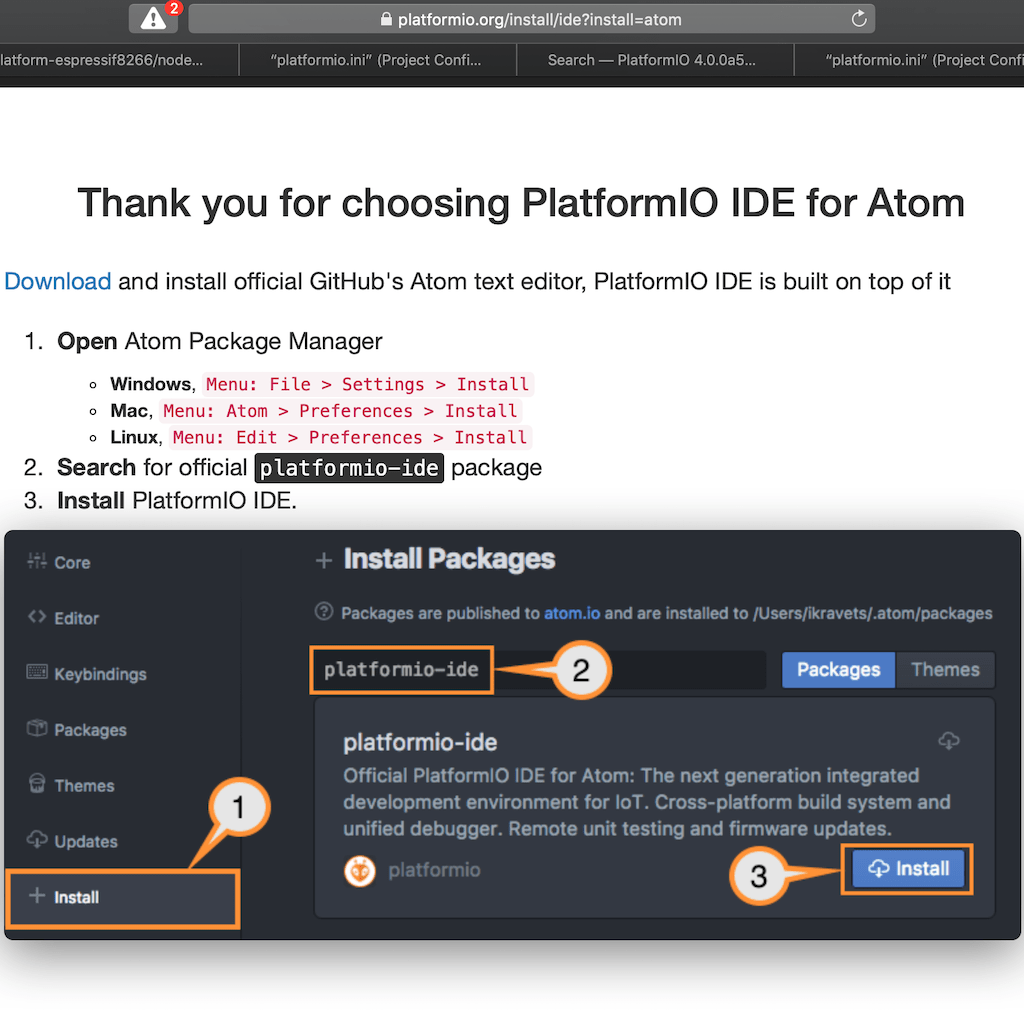
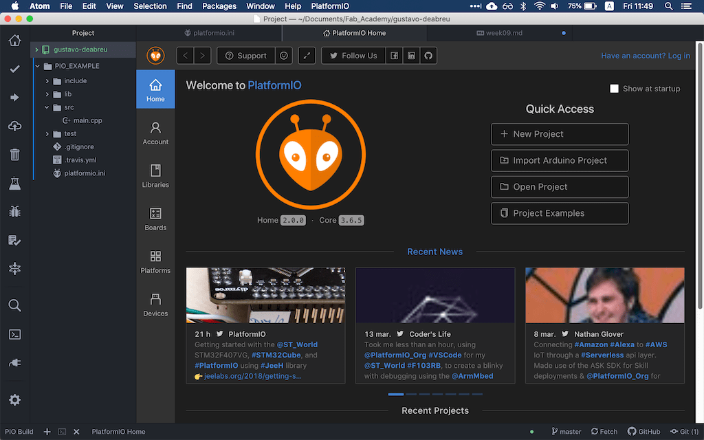
Then, I was greeted with the welcome screen and was ready to start working.
ESP8266
I wanted to try a ESP8266, since I heard a lot about it and we had a couple NodeMCUs laying around in the lab.

But, since nothing works as expected, the board I chose to use was not showing as a COM port. Even tough it was lighting up.
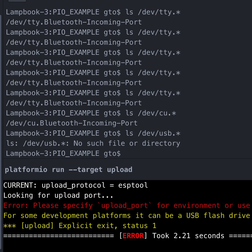
After two hours trying different boards, cables, computers and drivers, found this lonely comment on github with the solution.
In MacOS Mojave, you need to give permission for the driver to run.

After doing that, everything started to work as it should.
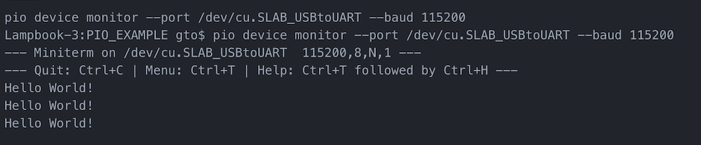
First, I tried the hello-world print using serial
#include <Arduino.h>

void setup() {
  Serial.begin(115200);//Set the baudrate to 115200,same as the software settings
}

void loop() {
  Serial.println("Hello World!");//Print character string“Hello World!”on the serial
  delay(5000);// Delay 5 second
}
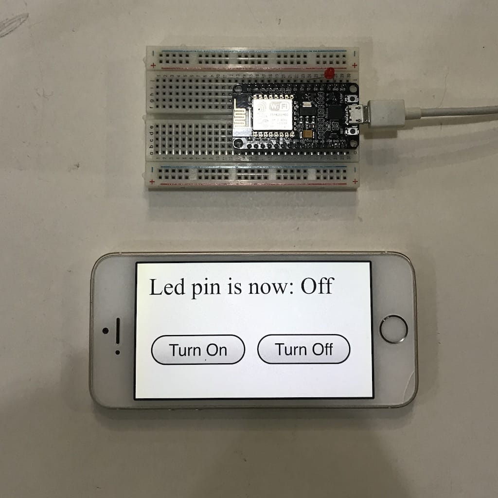
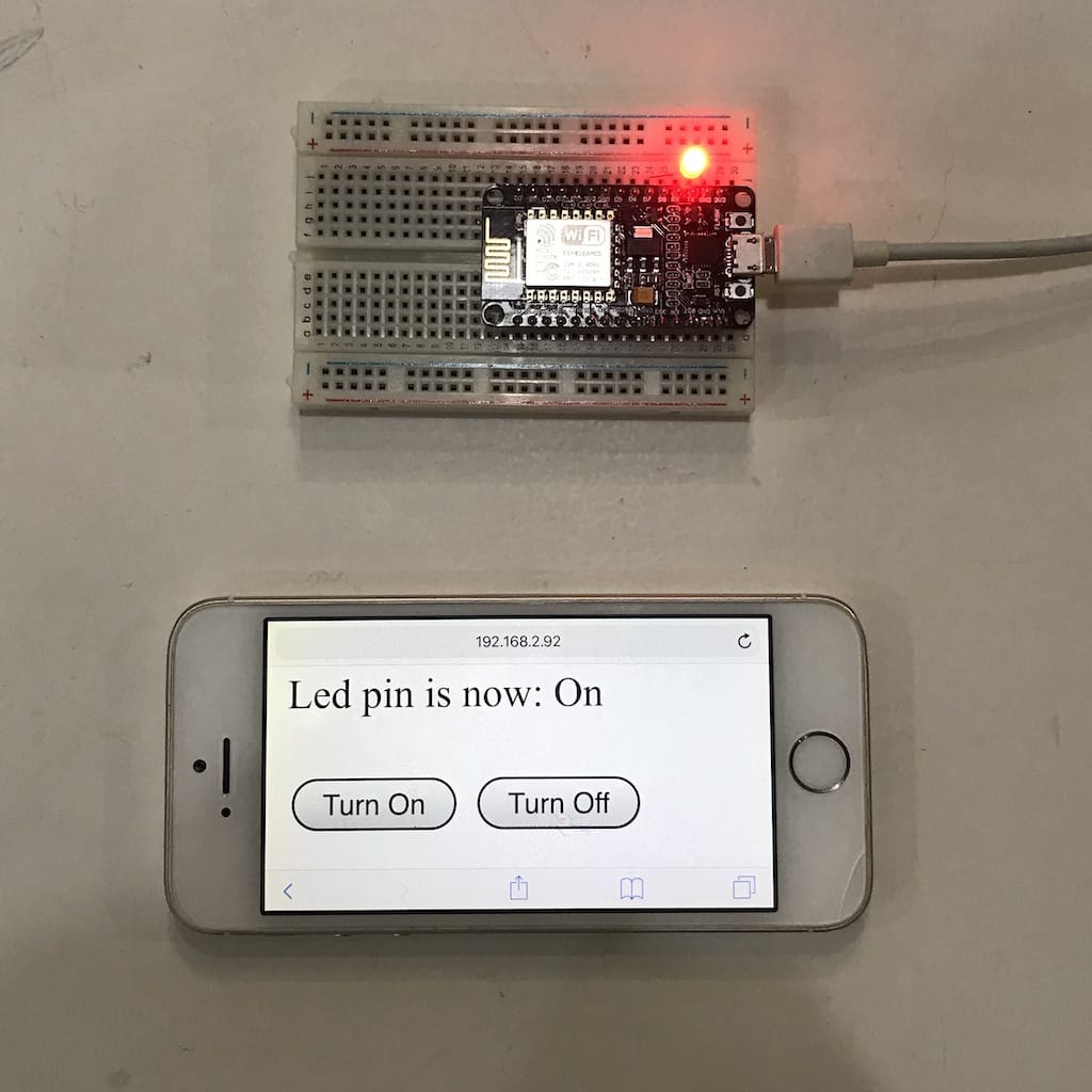
Then, went to the part I was most interested. Controlling something through Wifi. I found this great tutorial on instructables and got it to work in a few minutes.
Connecting to FAB-WIFI
.............................................................
WiFi connected
Server started
Use this URL to connect: http://192.168.2.92/
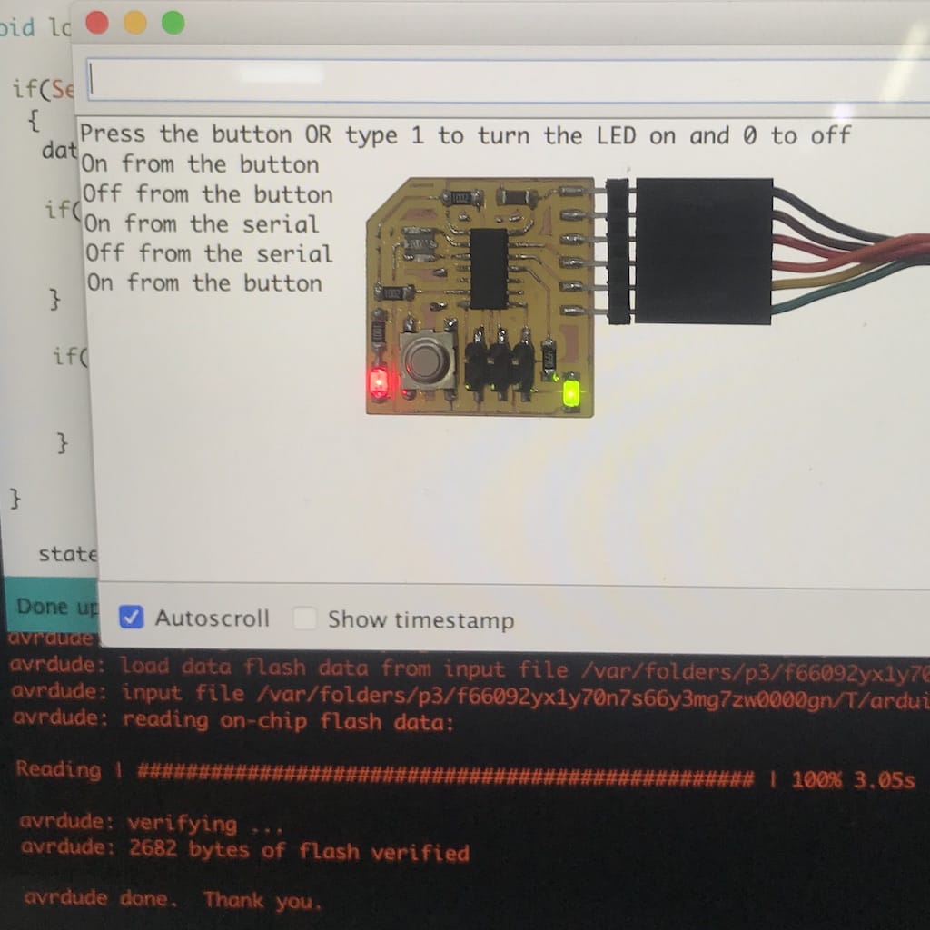
Hello board program
I wanted to finish my code from week 07. Where I had the board turning the LED on and off from pressing the button. But I wanted to control it from serial as well.
F() Those Strings!
But when I tried to compile the code, got a message that I ran out of space for the variables.
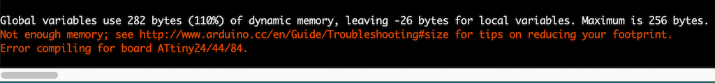
The only thing I added on top was
int state = Serial.parseInt();

  if (state == 1)
  {
    stateLED = HIGH;
    Serial.println("LED ON from Serial");
  }

    if (state == 2)
  {
    stateLED = LOW;
    Serial.println("LED OFF from Serial");
  }
The error was not intuitive. Even reading the arduino.cc article did not help. I spend a couple of minutes thinking I had allocated too many variables in my code. When in reality, I was running out of SRAM because I had too many print lines, by default they are stored there as well the program loads.
But you can use F() to move store the strings in the program memory instead of the ram.
print(F(""));
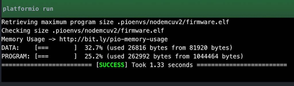
Since I had a lot of program space left, I used this with all my prints and then everything worked fine.
I did not get in too deep in this, but found a great article by adafruit explaining how to optimize SRAM in your code
Final code
#include <SoftwareSerial.h>

SoftwareSerial Serial(0, 1);
int pushButton = 7;
int LED = 2;
int stateLED = LOW;
int stateButton;
int previous = HIGH;
long time = 0;
long debounce = 200;
char data = 0;

void setup() {
  pinMode(pushButton, INPUT);
  pinMode(LED, OUTPUT);
  Serial.begin(115200);
  delay(2000);
  Serial.println(F("Press the button OR type 1 to turn the LED on and 0 to off"));
}

void loop() {

  if(Serial.available()>0 )      // Send data only when you receive data:
   {
    data = Serial.read();

    if(data == '1'){
       stateLED = HIGH;
       Serial.println(F("On from the serial"));
    }

    if(data == '0')    {
       stateLED = LOW;
       Serial.println(F("Off from the serial"));
    }

}

  stateButton = digitalRead(pushButton);
  if (stateButton == LOW && previous == HIGH && millis() - time > debounce) {
    if (stateLED == HIGH) {
      stateLED = LOW;
      Serial.println(F("Off from the button"));
    } else {
      stateLED = HIGH;
      Serial.println(F("On from the button"));
    }
    time = millis();
  }
  digitalWrite(LED, stateLED);
  previous == stateButton;

}
BLE and iOS programming
Since I was with the programmer spirit, I decided to start working with my final project as well.
Started this week by getting a SH-HC-08 Bluetooth adaptor for my device. I want to understand better how it works so I can integrate it with my device.
But, I have no idea how it works. So the first step is always to google some kind of instruction.
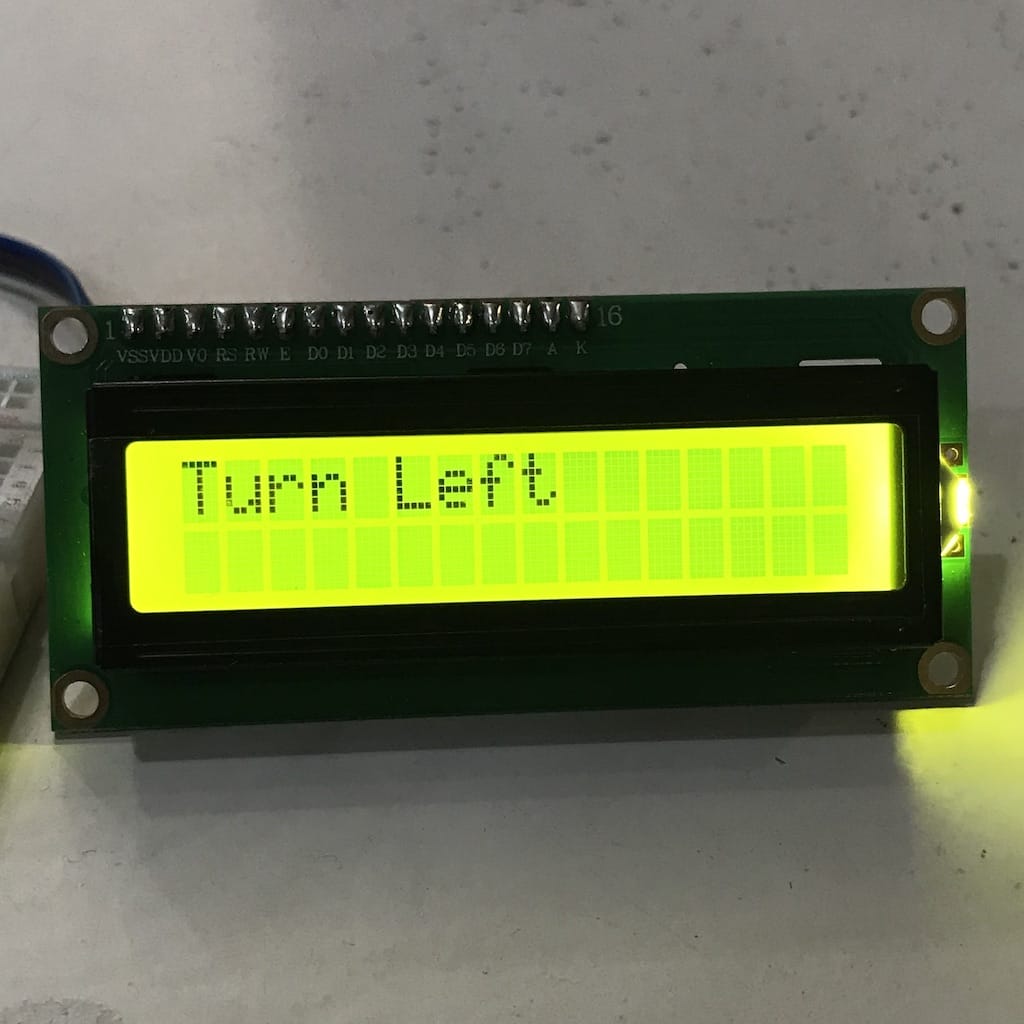
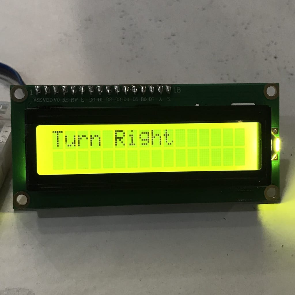
Found a really basic youtube video showing how to wire and program the board to light an LED with a bluetooth command. So I copied the code and changed it to show directions on the LCD screen.
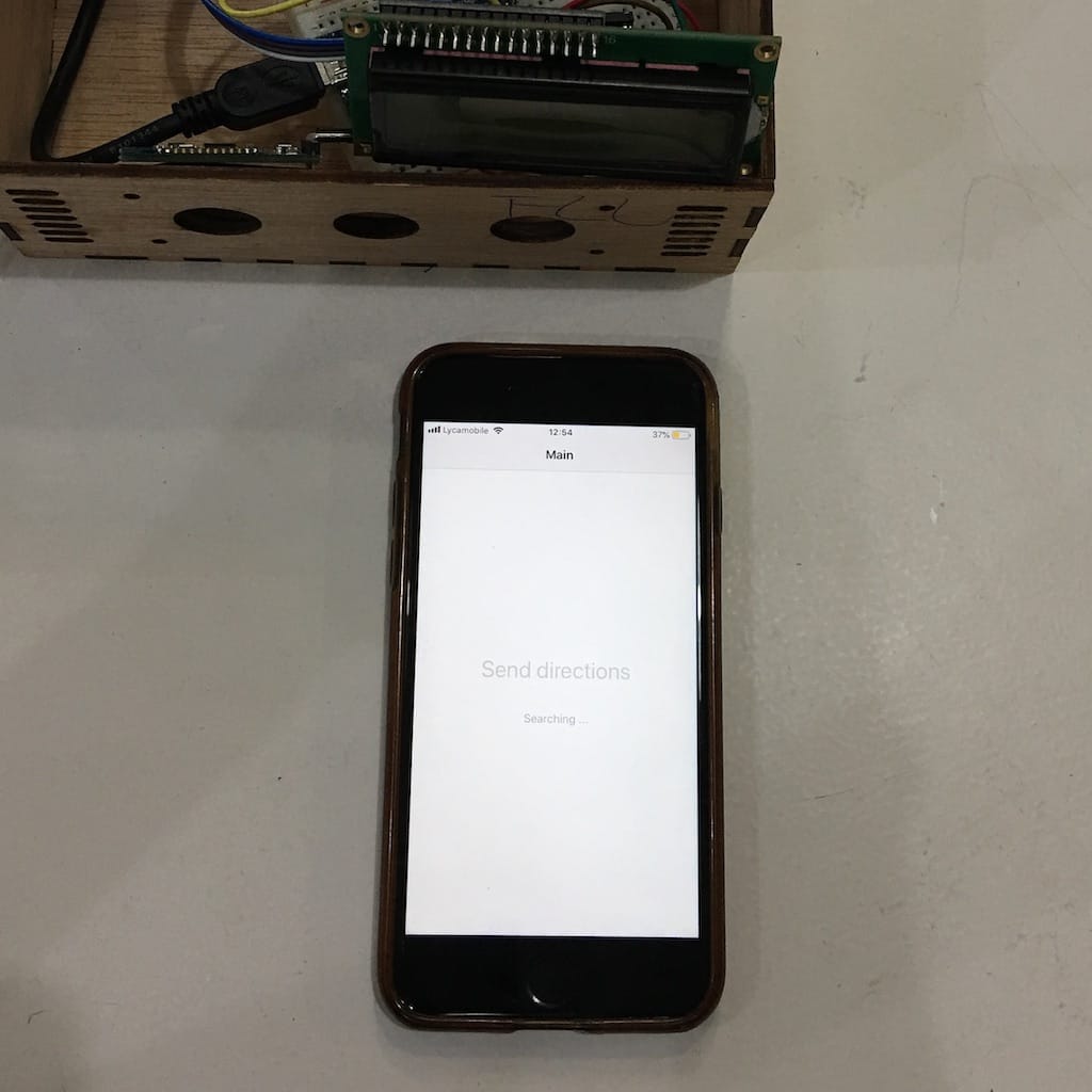
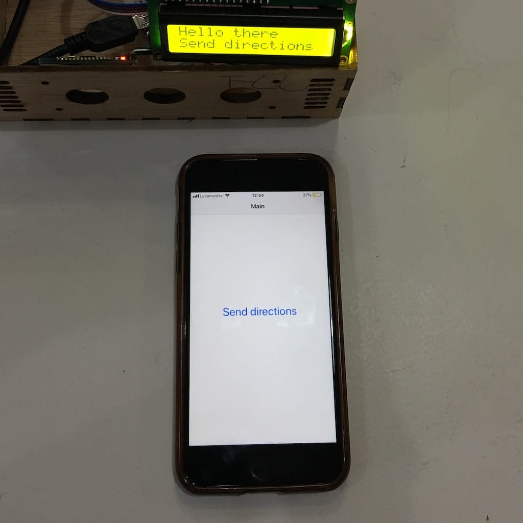
After wiring everything, I was able to light the LCD screen and connect to bluetooth.

Then, updated the code and was able to send directions from the phone via the bluetooth terminal app.
But, since I’ll have to integrate with a map, I believe the best way is to create my own app and send the directions to the display.
The first shock was using Xcode and the Swift language for programming, but after going though a hello world tutorial, I was able to navigate better.
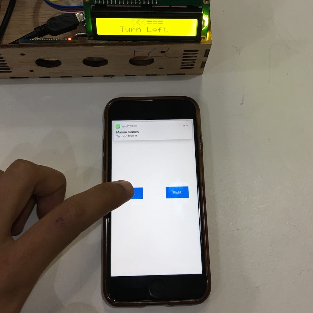
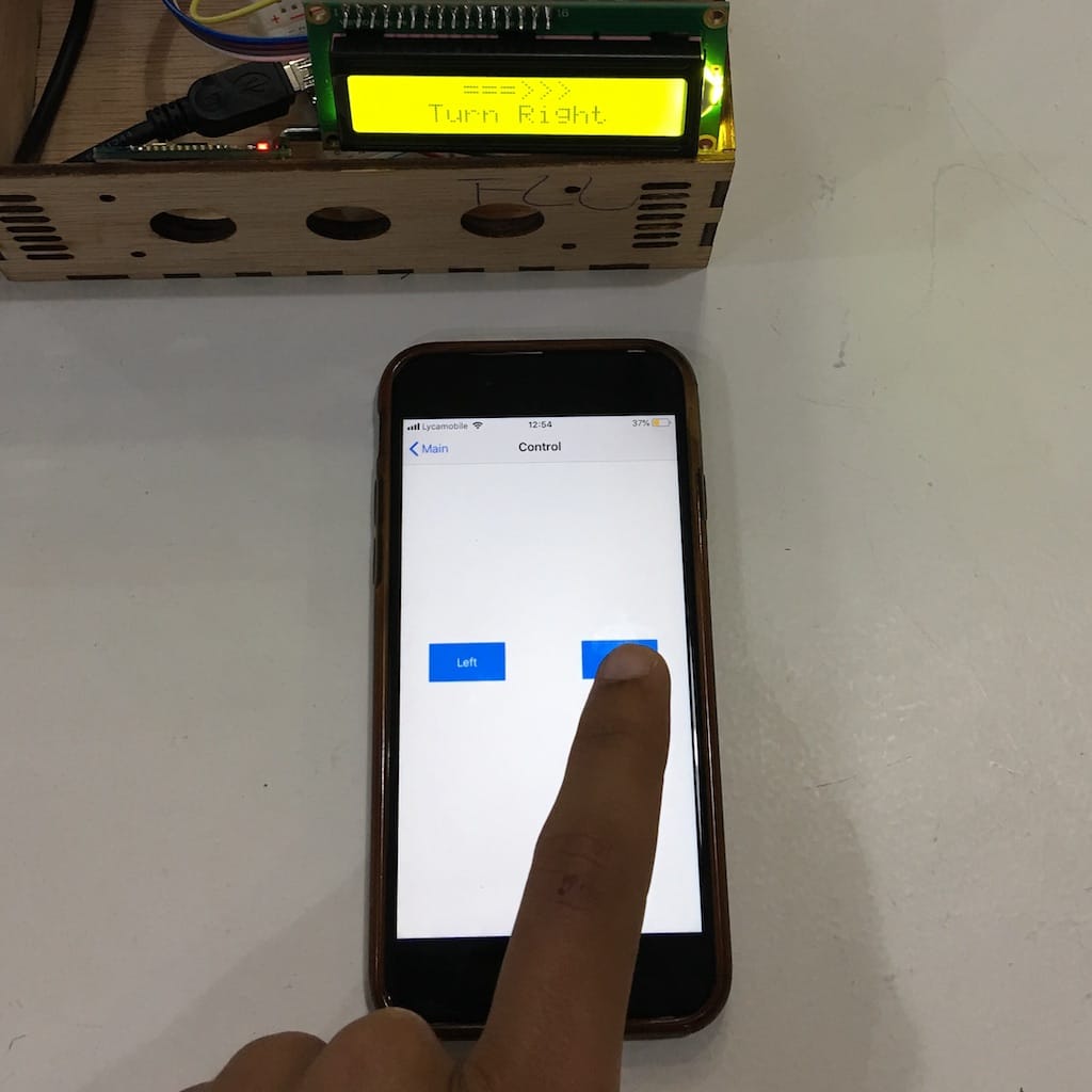
I found a perfect example using BLE and a iOS app to control a arduino rc car. All I did was change the directions toggles with two buttons and added this piece of code
var mainPeripheral: CBPeripheral?
var mainCharacteristic: CBCharacteristic?

private func sendLeft() {
   guard let peripheral = mainPeripheral, let characteristic = mainCharacteristic else { return }
   var direction = "L"
   let data = Data(buffer: UnsafeBufferPointer(start: &direction, count: 1))
   peripheral.writeValue(data, for: characteristic, type: .withoutResponse)
}
private func sendRight() {
   guard let peripheral = mainPeripheral, let characteristic = mainCharacteristic else { return }
   var direction = "R"
   let data = Data(buffer: UnsafeBufferPointer(start: &direction, count: 1))
   peripheral.writeValue(data, for: characteristic, type: .withoutResponse)
}

@IBAction func btn_left(_ sender: Any) {
   sendLeft()
}
@IBAction func btn_right(_ sender: Any) {
   sendRight()
}
Spent a couple of hours trying to figure everything out. I still don’t understand much but was able to create an app to connect and send the characters to the Arduino.