14. Networking and Communications
individual assignment:
- design, build, and connect wired or wireless node(s) with network or bus addresses
group assignment:
- send a message between two projects
Available Bluetooth chips on the lab
BL652-SA-01-CT-ND*
1446-1017-1-ND
450-0104-ND
After a lot of reading, they all seem a lot of work for now, since I already have an inexpensive SM-HC-08 board based on the CC2541 chip.
AVR programming over Bluetooth
https://sites.google.com/site/wayneholder/inexpensively-program-your-arduino-via-bluetooth
All the guides I found required a signal inverter between the bluetooth module and the board. But I asked and we don’t have them here.
One option is invert the signal logic on the chip, I saw a command in different places but I’m not sure it will work. So this is the first thing I’ll try. Because if not, it will be hard to do it.
https://circuits4you.com/2016/06/19/bluetooth-module-at-command/
Unfortunately, this module doesn’t respond to the AT commands I need in order to program a MCU through it. So I’ll be skipping this for now, and consider it a feature to be added after the first version is done.
Previous work
Over the past weeks, I’ve been working with BLE to send messages as it will be the main channel of communication used on my final project. Most of it is documented on my development page.
So far, I haven’t dived too deep into the way BLE work, but got a grasp into peripherals, characteristics, and serial. My goal for this week is to further understand it’s workings to develop a more tailored solution for my final project.
One feature that really interested me was the ability to program a MCU through Bluetooth. This would fit my project perfectly as the user would be able to update the device’s firmware using only the iOS App.
This + wireless charging would give me everything needed to make a complete sealed enclosure, making it easier for it to be water resistant.
iOS app
My latest work was during the break. I made an iOS navigation app to send directions over BLE.
After using the HC-08 module for the past weeks, I already knew the default name and characteristic to use the BLE as a simple serial channel.
Since I did not wanted to go through scanning and selecting the device, I included all the info on the code so it would do it automatically.
// Declare service and characteristic ids
let Service_CBUUID = CBUUID(string: "FFE0")
let Characteristic_CBUUID = CBUUID(string: "FFE1")

// Scan bluetooth to find a peripheral with the service declared
centralManager.scanForPeripherals(withServices: [Service_CBUUID])

// If discovered, stop scanning and connect to peripheral
func centralManager(_ central: CBCentralManager, didDiscover peripheral: CBPeripheral, advertisementData: [String : Any], rssi RSSI: NSNumber) {

        // class instance variable
        peripheralHRM = peripheral

        // stop scanning to preserve battery life;
        centralManager?.stopScan()

        // connect to the discovered peripheral
        centralManager?.connect(peripheralHRM!)

    }
I believe the navigation logic is a bit out of scope here, so I’ll simplify and only demonstrate how it is being sent. This is being called whenever the user’s location updates:
// Sends utf8 string over BLE
// string being current maneuver direction, distance to maneuver and street name
peripheralHRM.writeValue(string.data(using: String.Encoding.utf8)!, for: myCharacteristic!, type: CBCharacteristicWriteType.withoutResponse)
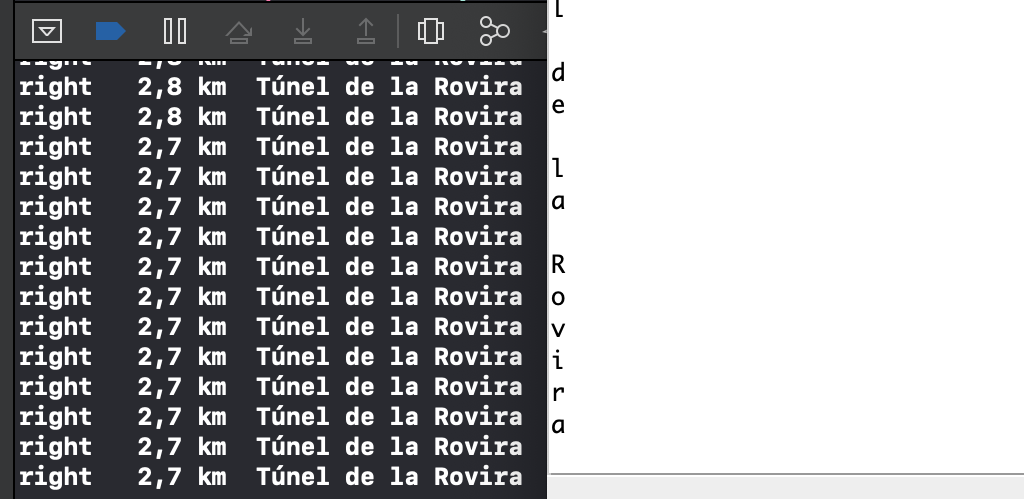
Then, I needed the Arduino to read what was being sent and print it again over serial and display.
// Parses the data received into strings
String getValue(String data, char separator, int index)
{
    int found = 0;
    int strIndex[] = { 0, -1 };
    int maxIndex = data.length() - 1;

    for (int i = 0; i <= maxIndex && found <= index; i++) {
        if (data.charAt(i) == separator || i == maxIndex) {
            found++;
            strIndex[0] = strIndex[1] + 1;
            strIndex[1] = (i == maxIndex) ? i+1 : i;
        }
    }
    return found > index ? data.substring(strIndex[0], strIndex[1]) : "";
}

void loop() {

  if(mySerial.available() > 0){
    myString = mySerial.readString();
    maneuver = getValue(myString, '\t', 0);
    distance = getValue(myString, '\t', 1);
    street = getValue(myString, '\t', 2);
  }

  Serial.println(maneuver);
  Serial.println(distance);
  Serial.println(street);
}
Whit this, I’ve achieved a very simple working prototype:
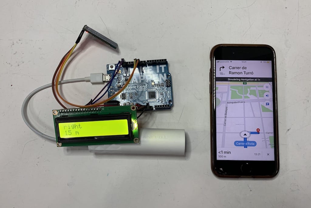
As you can see on the video, there is a little bit of delay between the string sent from the phone and the MCU’s print.
So that’s what I’ll focus to solve for now.
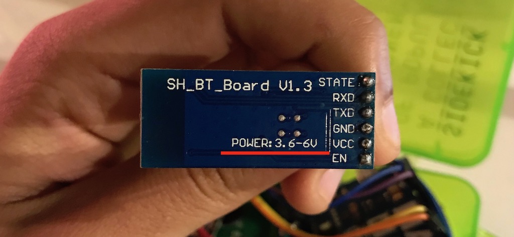
Even though the module works on 3.3v, the board it comes states that it should be powered with 3.6-6v.
Since I was powering it with 3.3v this may be the problem as well… So setting up a new environment will be great to test this.
But before, to not have a lot of variables debugging, I’ll take what I have now and power it with 5v to see if it makes any difference.
HC-08 voltage test
As stated above, I’m facing a slow speed of transmission between my app and the MCU. One of the possible problems is that I was under-powering the module. So I’ll compare the results between 3.3v and 5v supply.
The module datasheet states that it is 3.3v, but the board it comes with says 3.6-5v.
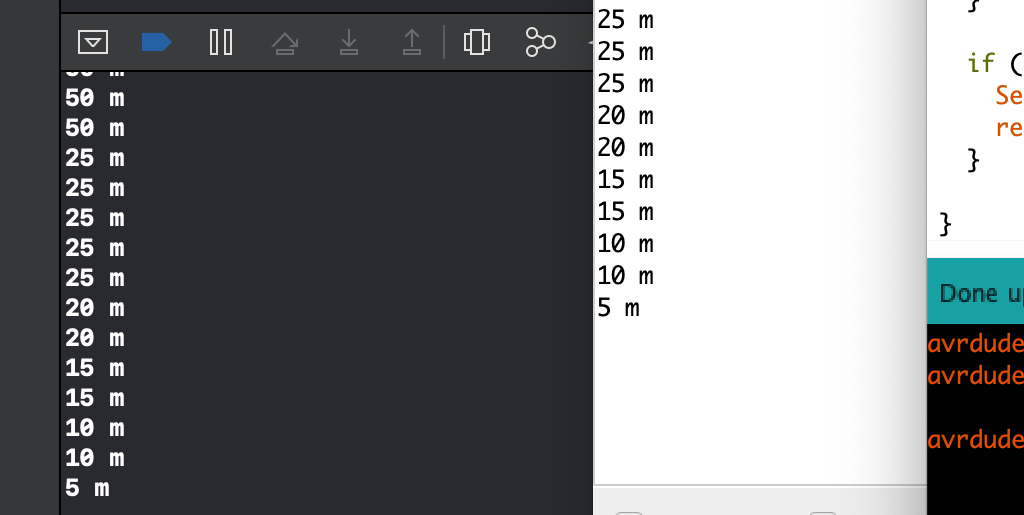
So to start, I’ll hook up everything again the recreate the problem.
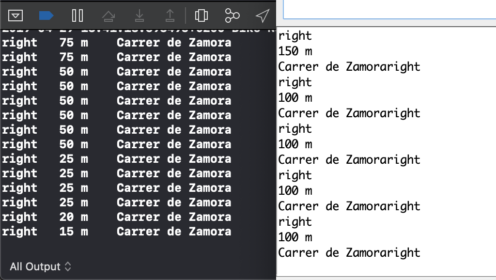
As you can see the outputs are way off.
After powering it with 5v, there is still some lag. So I’ll start editing the code.
HC-08 communication troubleshooting
Sending navigation updates as string
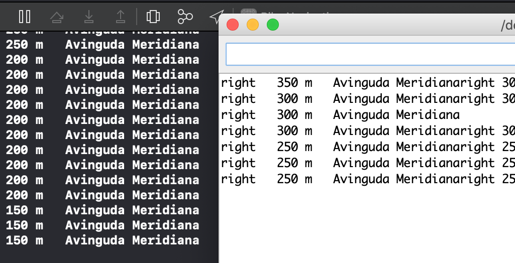
Since changing the voltage did not solve the problem. I’ll start to troubleshoot the communication.
I’ve simplified it and now I’m having a couple of concatenated strings, no idea why.
This is the code
SoftwareSerial mySerial(10, 11); // RX, TX

String myString = "";

void setup() {
  Serial.begin(9600);
  mySerial.begin(9600);
}
void loop() {

  if(mySerial.available() > 0){
    myString = mySerial.readString();
    Serial.println(myString);
  }

}
My end goal is to have the same output on both sides.
So I’ll head back to basics and just send a know char to make sure everything under it is working.
Sending basic known char on each position update
If I send only a char and read it, they are both in sync. So the problem is not on the transmission.
iOS:
let char = "A"
peripheralHRM.writeValue(char.data(using: String.Encoding.utf8)!, for: myCharacteristic!, type: CBCharacteristicWriteType.withoutResponse)
Arduino:
char myChar = "";
if(mySerial.available() > 0){
  myChar = mySerial.read();
  Serial.println(myChar);
}
Sending string but not parsing it
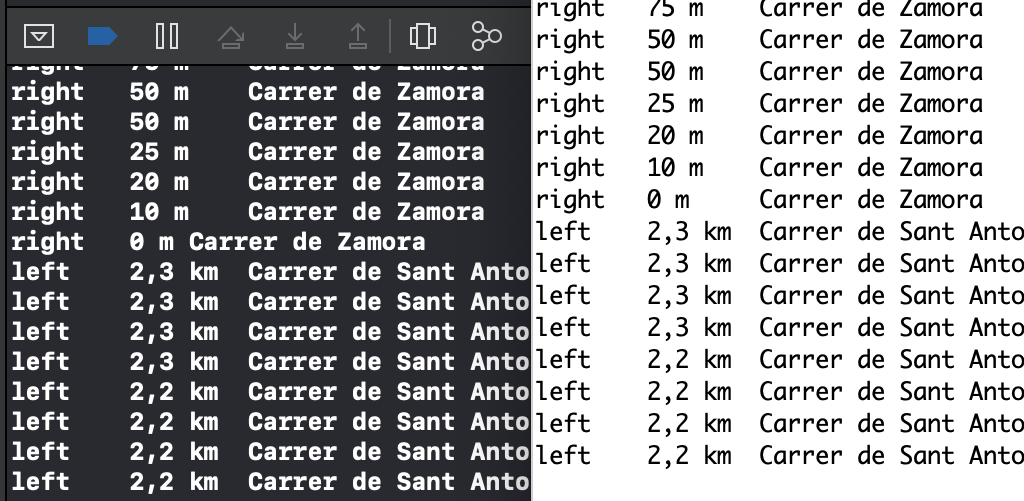
So now I’ll leave the Arduino code as is, and send the whole string to see what happens.
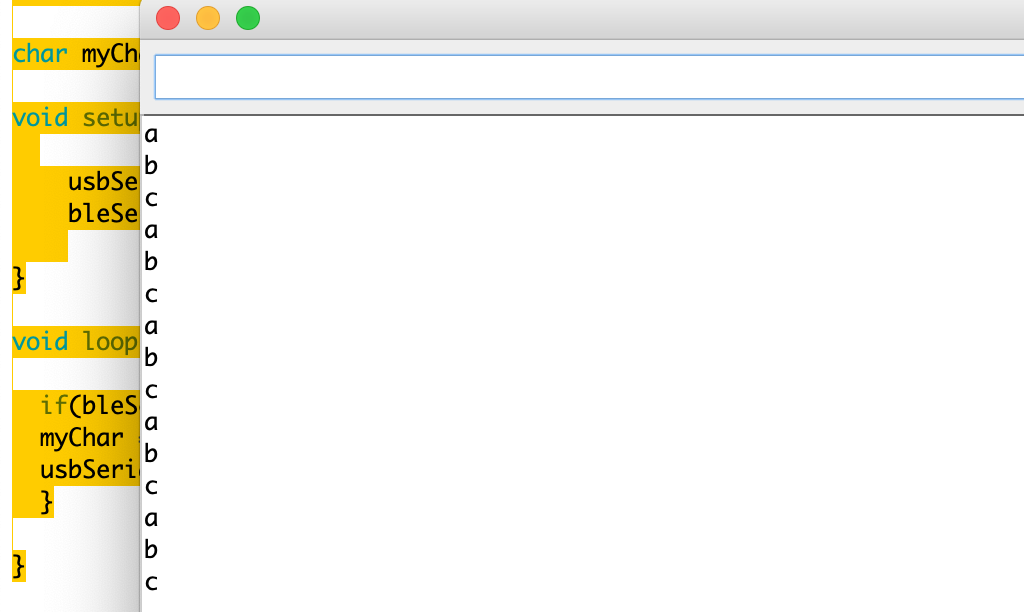
The Arduino is printing each char of the string on a new line, but everything is perfectly in sync. So the problem is in parsing the string received and printing it.
Parsing the bluetooth bytes
Now that I know using a char works, I could just send everything encoded into chars or ints, but this would mean changing a lot of swift code that I’m not so familiar with.
Instead of doing that right now, I’ll try parsing the string in a more effective way.
But to make it simpler, I’ll reduce it to just the distance.
After a bit of research I discovered that the readString() function in Arduino is super slow. So instead you should build the string out of the characters in the serial buffer.
void loop() {

  while (mySerial.available()) {
    char c = mySerial.read();  //gets one byte from serial buffer
    readString += c; //makes the String readString
    delay(2);  //slow looping to allow buffer to fill with next character
  }

  if (readString.length() >0) {
    Serial.println(readString);  //so you can see the captured String
    readString="";
  }

}
Now I’m getting the strings in sync.
So I hopped back into the swift code and changed it to send the whole string.
It is still in sync!
Parsing the string to display
Now that I’m receiving the string in sync, I need to parse and display it.
This is my final Arduino code:
void loop() {

  while (mySerial.available()) {
    char c = mySerial.read();  //gets one byte from serial buffer
    readString += c; //makes the String readString
    delay(2);  //slow looping to allow buffer to fill with next character
  }

  if (readString.length() >0) {
//    Serial.println(readString);  //so you can see the captured String
    maneuver = getValue(readString, '\t', 0);
    distance = getValue(readString, '\t', 1);
    street = getValue(readString, '\t', 2);
    Serial.println(maneuver);
    Serial.println(distance);
    Serial.println(street);
    readString="";
    lcd.clear();
    lcd.setCursor(0,0);
    lcd.print(maneuver);
    lcd.setCursor(0,1);
    lcd.print(distance);
  }
}
3.3v test
Now that everything is working as intended. I’ll plug the bluetooth module back in 3.3v to see if it makes any difference.
It is still in sync!
Hello board with bluetooth module
Logic
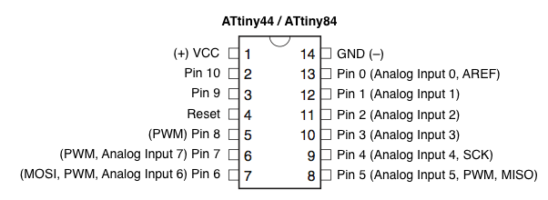
Since we cannot use an Arduino for this assignment, I’ll hook up the HC-08 module with my hello board.
This will be super helpful since I’ll eliminate a couple of variables and make the cleanest code as possible to get the data transmitted and parse it.
The module wiring is really simple:
VCC -> 5v
GND -> GND
TX -> Pin 4
RX -> Pin 5
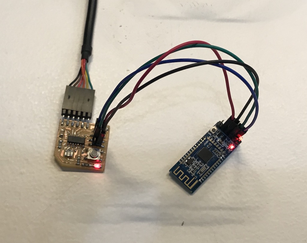
With this I can use the FTDI cable to have serial with the computer and power the board.
And, with the ISP connection, power the bluetooth module and use the other pins as TX and RX.
Wiring
Code
To make it simple, started with only a char
#include <SoftwareSerial.h>

SoftwareSerial usbSerial(0,1);
SoftwareSerial bleSerial(4,5);

char myChar = "";

void setup() {

    usbSerial.begin(115200);
    bleSerial.begin(9600);

}

void loop() {

  if(bleSerial.available() > 0){
  myChar = bleSerial.read();
  usbSerial.println(myChar);
  }

}
Results
Then, the output on the usb serial:
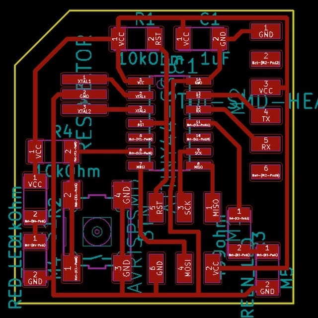
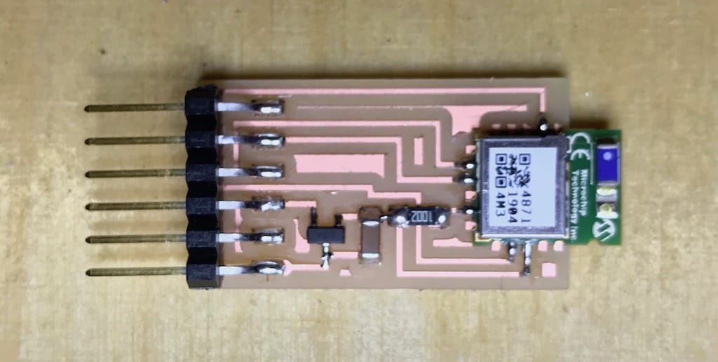
Making my own board
Other than using a commercial board, I wanted to make my own as well. The original goal was to use a nRF52, since it gives me the ability to exclude the MCU and use only the bluetooth chip. But it involves using a different architecture, development board, etc. So I decided to go for a simpler one (RN4870) we had in stock.

Apparently this board uses a complete different logic compared to the AT commands from the HC-08. Especially it is not plug and play. You need to configure the module to work as you want.
I found a great documentation by a fellow student, that explains a lot about the layers and fundamentals of BLE. Joris navarro’s Networking week
So far I’ve been using the HC-08 as connected central/peripheral profiles. And that is my goal to achieve with this new board.
Serial ECHO test
Following Neil’s class, I configured the board in ECHO mode to test its functionality. For that, I had to connect the board with the FTDI cable.
ftdi connection PICTURE
List my connected devices ports
ls /dev/tty.*
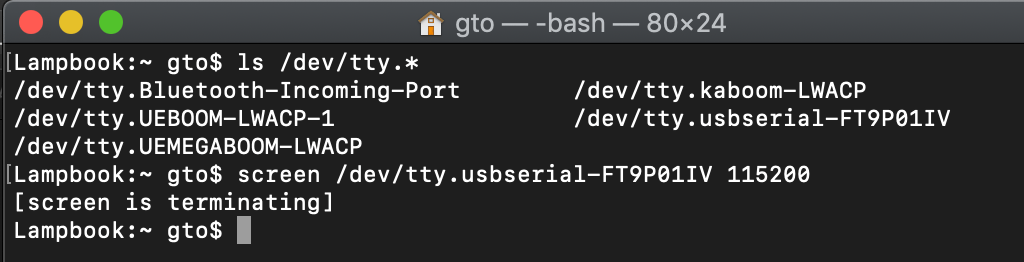
Connect to port using serial
screen /dev/tty.usbserial-FT9P01IV 115200
Then I typed this keys in order to get everything working. This basically enters command mode, turn on ECHO, sets it in UART Transparent mode, then reboots.
$$$
+ [Enter]
SS,C0
R,1
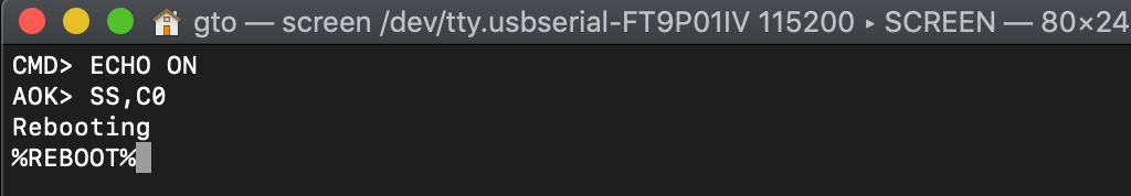
To exit the screen terminal (Not super intuitive): Control + a + \
Now I can send messages back and forth between the phone and terminal through the BLE module.
![]()
For now, this seems to be enough for my project to work, since I’m able to send the messages from the phone and read in the computer.
Going forward I’ll add this to my device and hopefully print the strings on the display.
Group assignment
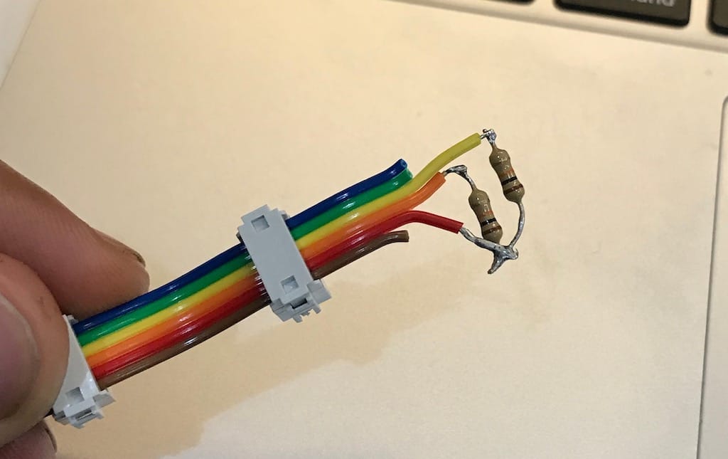
For communicating between projects, I’ve paired with Josep Marti and Diar Amin. We decided to use the ribbon cable already assembled to create an i2C hub and talk with our hello boards.
For I2C to work we need two PullUp resistors, like this:
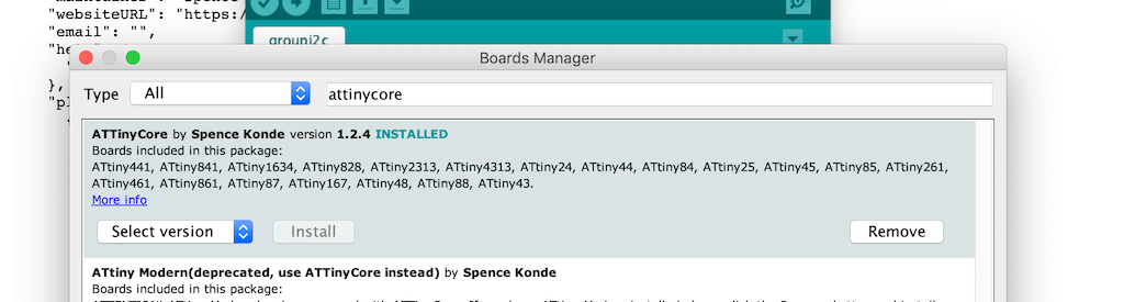
Since we’ll be using Attiny44s and it doesn’t support the Arduino wire library. The first step is to add the AttinyCore from this link to arduino, then install it on the boards manager.
By adapting Josep’s code, we managed to get all boards talking and changing the master’s color when pressing the buttons.
This is the master’s code:
#include <Wire.h>

int State[] = {0, 0, 0};

int but=8;
int R=7;
int G=2;
int B=3;

int Gustavo = 1;
int Diar = 2;

void setup() {
  Wire.begin();
  delay(5000);
}

void loop() {
  if (digitalRead(but)== HIGH) {
    analogWrite(R,255);
    analogWrite(G,0);
    analogWrite(B,255);
    State[0] = 1;
  }

  else {
    analogWrite(R,255);
    analogWrite(G,255);
    analogWrite(B,0);
    State[0] = 0;
  }
  readU();
  writeU();
  delay(10);
}

void readU() {
  Wire.requestFrom(Gustavo, 1);
  State[1] = Wire.read();
  Wire.requestFrom(Diar, 1);
  State[2] = Wire.read();
}

void writeU() {
  Wire.beginTransmission(Gustavo);
  Wire.write(State[2]);
  Wire.endTransmission();
  Wire.beginTransmission(Diar);
  Wire.write(State[0]);
  Wire.endTransmission();
}
This is the slaves:
#include <Wire.h>

int LED = 1;  //Change it for your LED pin
int But = 2;  //Change it for your Button pin

int Gustavo = 1;
int Diar = 2;
int LEDState = 0;
int ButState = 0;

void setup() {
  Wire.begin(Diar); //Change the name
  Wire.onReceive(receiveEvent);
  Wire.onRequest(requestEvent);
}

void loop() {
  if (digitalRead(But)==HIGH) {
    ButState = 1;
  }
  else{
    ButState = 0;
  }
  if (LEDState == 1) {
    digitalWrite(LED, HIGH);
  }
  else {
    digitalWrite(LED, LOW);
  }

}

void receiveEvent() {
  LEDState=Wire.read();
}

void requestEvent() {
  Wire.write(ButState);
}