6. 3D Scanning and Printing
assignments
group assignment:
- test the design rules for your 3D printer(s)
individual assignment:
- design and 3D print an object (small, few cm3, limited by printer time) that could not be made subtractively
- 3D scan an object (and optionally print it)
Group assignment
Test file
To test the different printers, the best option is to print a part that shows how the printer behaves in different situations. To do this, we’ve used a file from 3dprint.com available on thingiverse.
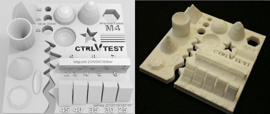
The article explains what should be measured as pointed below:
- Size: the object is 4 x 50 x 50 mm (baseplate) — measure with a caliper
- Hole size: 3 holes (3/4/5mm) — measure with a caliper/drill
- Nut size: M4 nut should fit perfectly — insert an M4 nut; it should need a little pressure
- Fine details: pyramid, cone, all numbers — check if all things look nice and smooth
- Rounded print: wave, half sphere — check if all things look nice and smooth
- Minimum distance between walls: 0.1/0.2/0.3/0.4/0.5 mm — depending on your nozzle size and slicer settings you will get different results
- Overhang: 25°/30°/35°/40°/45° — depending on printed material/cooling, these will not be as seen on the rendering provided
- Flatness: all flat areas — these should be flat with no gaps
We’ve used the same slicing parameters on every machine to have somewhat similar results. Although we could not use the same filament since the diameters were different.
Slicing settings:
Layer height: 0.2mm
Wall line count: 2
Top layers: 6
Bottom layers: 4
Infill: 20%
Speed: 60mm/s
Nozzle temp.: 205
Bed temp.: 60
Material: PLA
Printers description
Anycubic Kossel Plus

Area (x,y,z): 23x23x30
How to print: SD card
Nozzle diameter: 0.5mm
Filament diameter: 1.75mm
Axis movement: Delta
Ultimaker 2

Area (x,y,z): 22x23x20
How to print: SD card
Nozzle diameter: 0.4mm
Filament diameter: 3mm
Axis movement: CoreXY
RepRap

Area (x,y,z): 24x23x20
How to print: SD card or Octoprint
Nozzle diameter: 0.6mm
Filament diameter: 3mm
Axis movement: Cartesian
Prusa i3 Mk3

Area (x,y,z): 25x21x20
How to print: SD card
Nozzle diameter: 0.4mm
Filament diameter: 1.75mm
Axis movement: Cartesian
Print tests
Prusa i3
 Size: 4x50x50mm
Hole size: 4.7,3.7,2.5
Nut size: Snug fit
Fine details: Smooth
Rounded print: Smooth
Minimum distance between walls: 0.3mm
Overhang: Up to 45º smooth
Flatness: All closed
Bridges: Up to 9mm smooth
Ultimaker 2
 Size: 4x50x50
Hole size: 4.6,3.7,2.3
Nut size: Snug fit
Fine details: Smooth
Rounded print: Smooth
Minimum distance between walls: 0.3mm
Overhang: Up to 45º smooth
Flatness: All closed
Bridges: Up to 9mm smooth
Anycubic
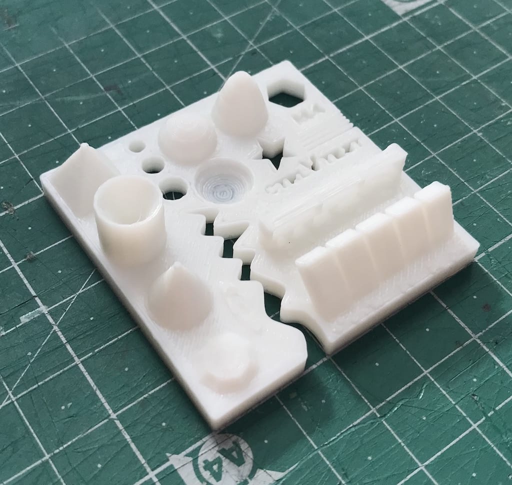 Size: 4.1 x 50 x 50 mm
Hole size: All of the drills almost fitted
Nut size: Almost fitted but not entirely
Fine details: Looks nice and smooth
Rounded print: Looks nice and smooth
Minimum distance between walls: Problems only with the 0.1/0.2mm wall distances but printed nicely
Overhang: No problem printing the overhangs
Flatness: Flat with no gaps
Bridges: It printed it all but with a little problem in the bridge of 6mm
Reprap
 Size: 4.1 x 49 x 49 mm
Hole size: Any of the drills fitted at all
Nut size: Doesn’t fit
Fine details: Looks nice but not smooth
Rounded print: Looks nice but not smooth
Minimum distance between walls: It could print only one wall with wrong distances
Overhang: No problem printing the overhangs
Flatness: Flat with no gaps
Bridges: No bridges at all
Conclusions
The Prusa i3 Mk3 did the best printings with accurate measurements, nice bridges, overhangs, spaces between walls and a lot of details. Anycubic and Ultimaker had similar good results.
The worst result was on the Reprap, we believe we could fine tune the slicing to improve the print. But, other than it having a 0.6mm nozzle, the main reason could be the old filament we’ve used. We may try again with a new one as soon as it arrives.
Since we had to use different softwares and filament between printers, we had very different results, but overall, they were good prints.
Individual assignment
My goal is to use this week to develop another enclosure for my final project.
Before starting, I decided to do a little bit of research on modeling for 3D printing. And I found great articles specially at 3DHubs.
Research
3DHubs - How to design snap fit joints
3DHubs - Enclosure design for 3D printing
3DHubs - How to assemble 3D printed parts
Sculpteo - 3D Printed enclosures design guidelines
How to design snap fit cases using Fusion 360
Design
My last experience with FreeCAD was a bit disappointing. Had lots of freezes and crashes that I could not fix in a reasonable time. So I decided to switch to Fusion 360 for this week.
Tutorial
Since I don’t have any experience with it. I tried following a tutorial to get a hang of it.
I found a tutorial directed at modeling an enclosure for 3D printing.
Since it’s not step-by-step, it took me a while to figure all the commands. But after one hour I got to the desired result.

Modeling
Enclosure
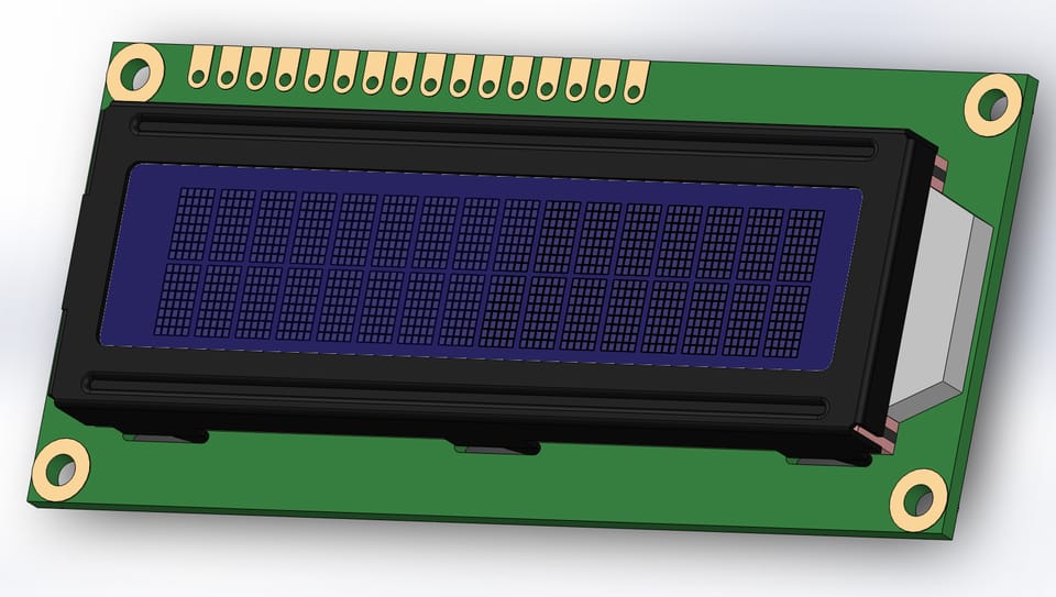
My workflow was supposed to to be similar to the tutorial I just did. But since I did not have the display with me for the weekend, I tried to google the dimensions and actually found this great 3D model by Anders Lohmann. It is pretty similar to the one I got from the lab.
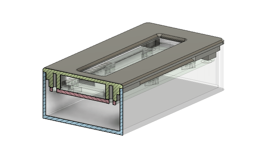
So the first step was to create a sketch of the perimeter and then extrude a shell. The recommendation is to use multiples of the printer’s nozzle diameter (0.4mm). So I created a 2.4mm shell.

As soon as I finished this, I remembered one of the recommendations of leaving 0.5mm of tolerance for prints. So the parts can actually fit together.
After

Then, added the display’s mounting points / holes for screws.

So far, I’m not worrying about the design being water resistant, so I’ll maintain the 0,5mm gap for the display as well.

Since I still don’t have all the components that will go inside de device, I’m leaving a lot o space and creating a simple lid, easy to open and close. If needed, I can add tape to hold or use a plier to make it more loose. Whenever I have more components I’ll add screws.

Out of “luck” (Google algorithms), I stumbled upon a great tutorial by Adafruit on how to design snap fit cases using Fusion 360. And it taught me not only that, but how to make the design more customizable using variables. My previous design was a bit difficult to modify.
So, a do over with parameters now :)

And now with a snap lid:

Then, imported the display again and added fixtures for the screws.
One thing I read on the comments was it was a bit difficult to take the lid off. So it would be better to add a little entrance gap for a fender somewhere along the perimeter of the lid.
Then, I had to figure how to fix it on the bike handle. That will be explained on the next section.
Mount
To save time and not reinvent the wheel, I decided to take a look online for GoPro like mounts. They are easy to use and everywhere. So it will be easy to replicate and use spare parts.
As soon as I actually start to use the device, I’m sure problems will appear and I’ll have to fix them anyways. I prefer to have an easy first prototype, to actually use and measure the results than to try figuring all out at once.

Found this file on thingiverse by andergrin.

For it to work, I had to simply add tabs with holes and then grab some screws from the lab. So thats what I did.

Looks great for a first version. Now it’s time to print and see the results.
3D Print
Since this pieces have features on multiple axis, it is possible but difficult to replicate the same piece with a subtractive process. It could have been done with laser cutting, but it would take a hole different design.
Fusion to 3D printer
Fusion has a very convenient export to stl option if you right-click the body you want to print.

Slicer
Opened all the files into Cura to make sure everything looked good.
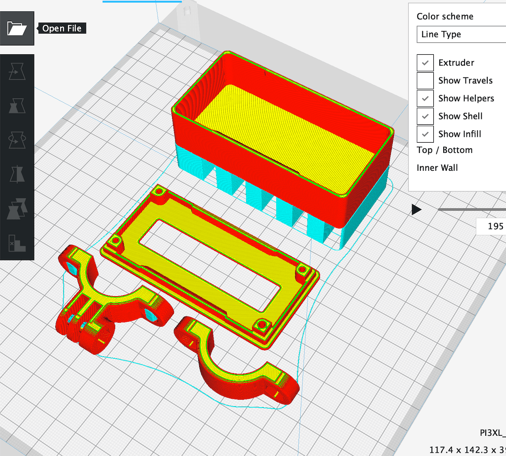
Used the following parameters
Quality   0,2mm
Shells    2
Tops      6
Bottoms   4
Infill    20%
Nozzle    205º
Bed       60º
Support   Yes
Printing
Since this Fab Academy class has almost 30 students, the printing queue was a bit crazy, so I had to use different machines and filament to print everything. But in the end, got to the expected results.
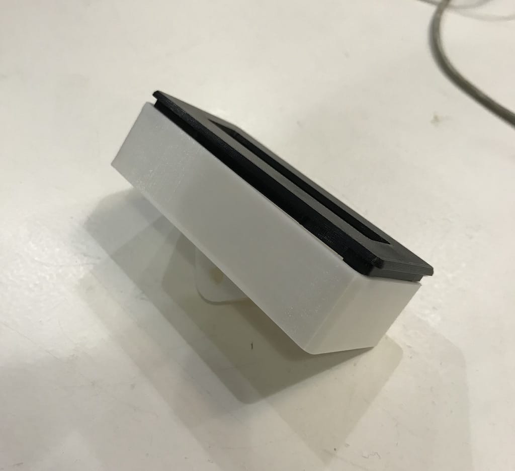
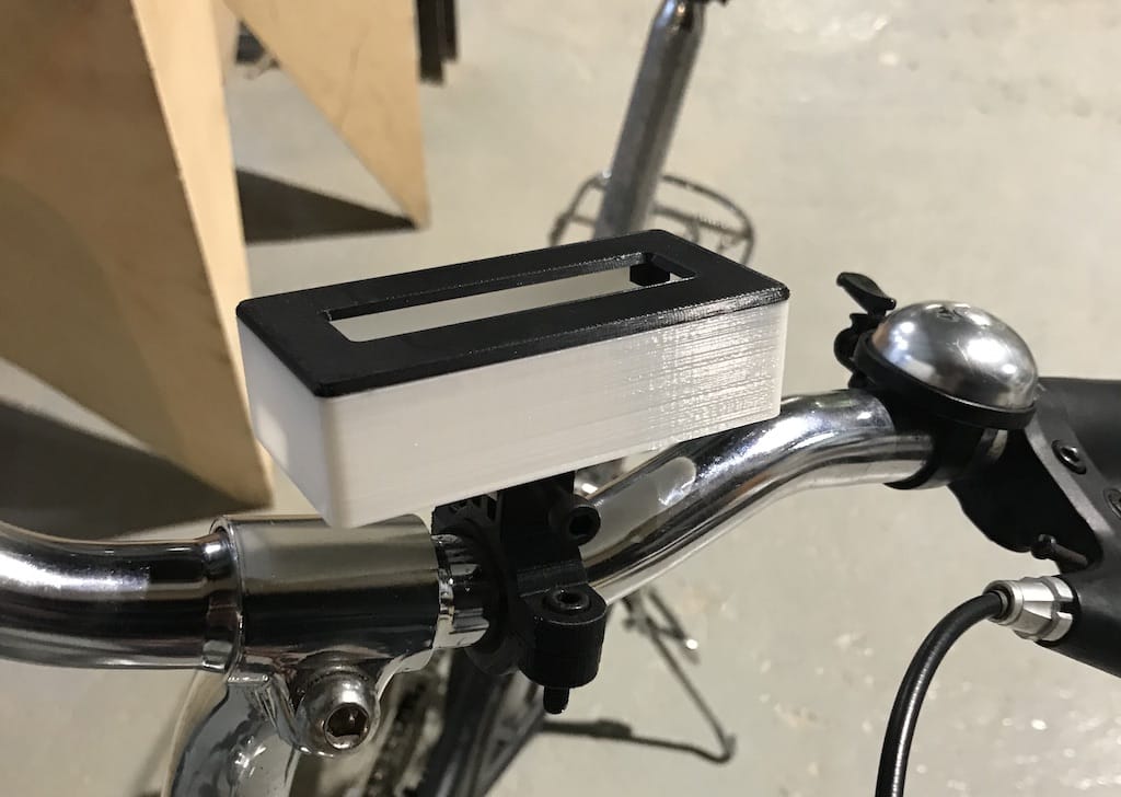
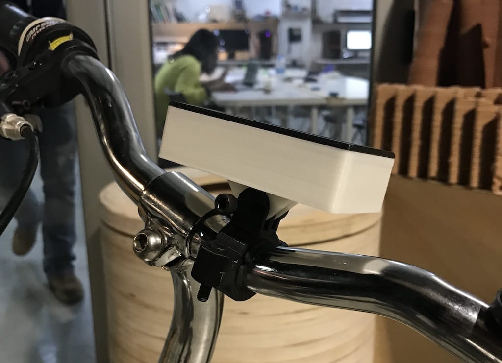
First thing was the bike mount.
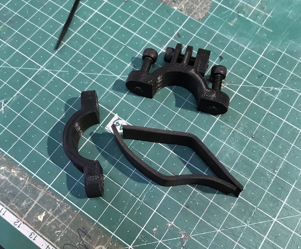
As described on the project, it needed foam pads to actually squeeze the handle. But it looked nice.

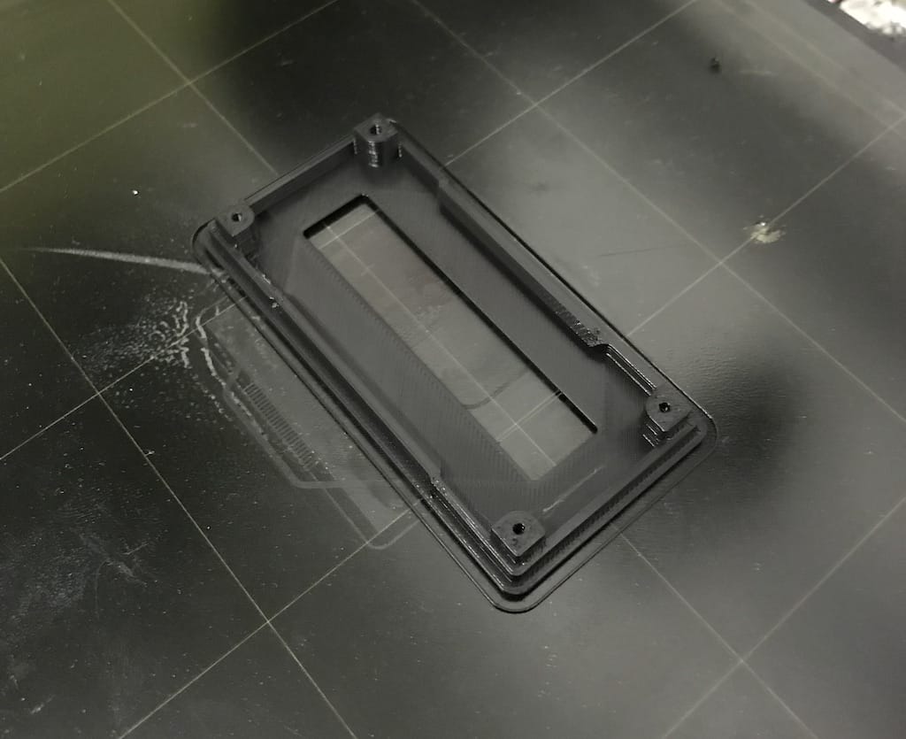
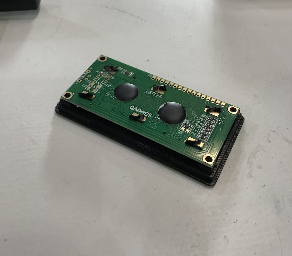
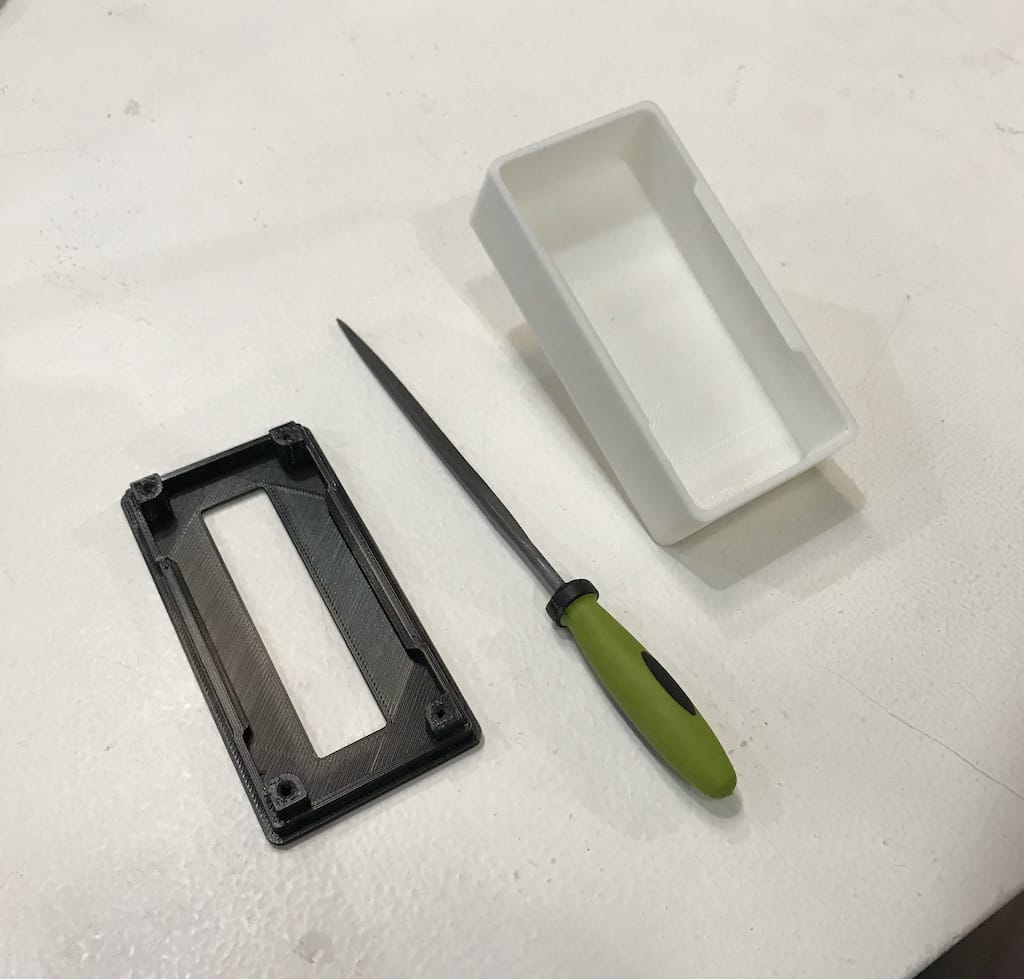
Then, the lid was ready and the display fitted really well. Only the holes were too tight. I had to push hard to get the screws in. So I’ll consider that on a next iteration.
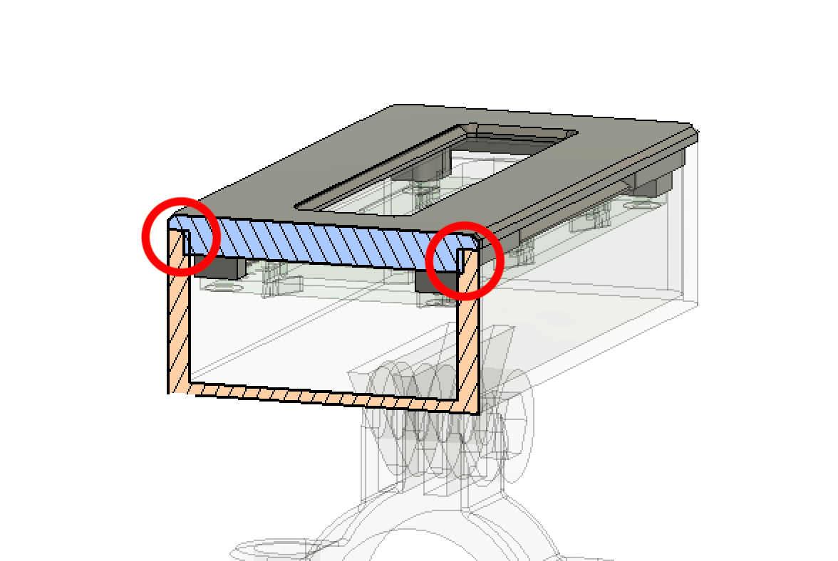
After getting the bottom part ready, I figured that for some reason the lid and the bottom did not fit together. Other than just fixing it, I decided to trace back where it came from. And it was actually a design problem. I’ve missed an overlap between the lid and the case.
So, a great way to correct this kind of 3d printing mistake is to use a good old file.
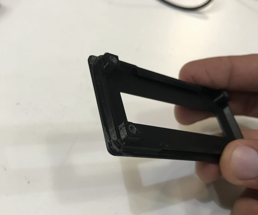
Then it was a perfect fit :)
3D Scan
Fab Lab Barcelona has a couple of methods to scan objects.
- Milk scanner
- Kinect
- Roland MDX-20 CNC with scan components
- Photogrammetry
I decided to use my phone and the Kinect for this week. Will updated as soon as I make it.
For the object, I found an old grinder laying around the lab. And think it will be a challenge to get every detail right. I’m supposing I’d scan it to create a replacement part with some digital fabrication machine.
Kinect - Skanect
One of the few programs supported by MacOS is Skanect. Thankfully it is free up to 5000 polygons, so it should me enough for this scan test.
https://skanect.occipital.com/download/#purchase
After installing and opening the program, I connected the Kinnect but nothing happened. I thought it was some driver problem but it was supposed to work out of the box.

The good old close and open it again made it work, and I could start scanning.

After selecting the dimensions and clicking start, you get to the scanning page.

Then, you need to click the record button and maintain the object within the range (always green) to be able to scan. But that turned to be a bit tricky.

The results are not good if everything is unstable.

So, I decided to use a rotating table. Since the lab doesn’t have one, I improvised with a chair and a round piece of wood I found laying around.

After two minutes rotating the base, the whole model was green, indicating it was mapped, and I stopped the recording.
Then, I just cropped the base off and made it watertight with a low smoothing.

A great feature is to export directly to sketchfab, just needing to add your private API for uploading.
Final result: