12. Output Devices
assignments
individual assignment:
- add an output device to a microcontroller board you’ve designed, and program it to do something
group assignment:
- measure the power consumption of an output device
I’ve already been playing with a couple of displays for my final project, but always using I2C and Arduino libraries. But so far, I was not pleased with their sizes. One was a 16x2 but with a large PCB and metal casing. The other, so small that it would make it difficult to create everything around it.
But today, going through our inventory, I found a better sized 16x2 display, so my goal is to make it work.
Depending on how things goes, If I manage to squeeze in the other components I need for the final project (usb charger, accelerometer and BLE), would be the best case scenario. But I’m learning to manage my expectations and make it simple :)
Since I’ve been seeing a lot if improvement in doing PCBs from scratch, my iterations will be as follows:
Spiral 1: Redraw Neil’s LCD board to fit the display size and make it work
Spiral 2: Add usb charger and LiPo battery
Spiral 3: Leave available pins for Accelerometer and BLE
Spiral 4: Integrate BLE and sensor on the board itself
By the end of Friday I want to have the display working. So I still have the weekend and two days in the lab to go through the other iterations.
I want to get the electronics for my final project ready as soon as possible. Since it depends a lot on code and I don’t have much experience. And that is going consume a lot of time.
Components and specifications
Display lcm-s01602dtr/m

Since I’m going to make a board that fit the display, it’s really handy to have every dimension on the datasheet

Design
I’m going to do two things I haven’t done before: Designing a board to fit something, and making holes.
So to start, I basically recreated Neil’s example of a display with a tiny 44.
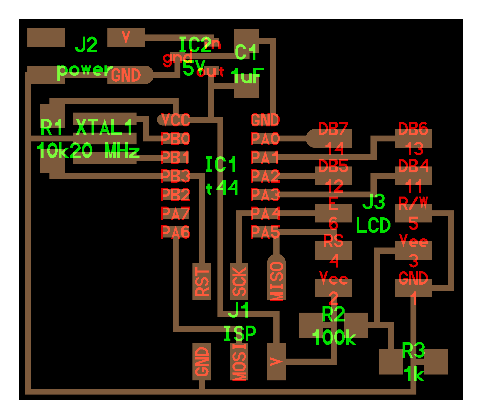

Since I could not find an easy way to draw in Eagle. I’ll do it in fusion and import it as a DXF.

And before going through milling. I decided to laser cut the vector just to make sure it would fit. So far it looks ok.


But, for some reason, when importing to Eagle it just drew the circles.

I found a script on the forums to import complex dxf into eagle but it did not work. So I separated the files in two. One for the outline and the other for the holes. But still no result.
Then, I opened the file in Rhino and exported again. And now it’s working. With the correct dimensions.

Before arranging everything. I started to think how the board would fit the display. And I have to really understand what I’m doing since there’s copper only on one side of the board. So I may have to flip the board to have the components on one side or the other.
Since I found a small battery that fits in between the board and the display. I’ll try to use male and female headers on both, so I can just snap them together and take it off if needed.
Designing to fit has being a challenge. But I like where it’s headed.

So, to make this work. I’ll have to flip the board, so the components are under everything. And, there will be no pin headers, just holes.
I really underestimated the amount of work it was to think of everything. Flipping the board, reducing the connections, making it fit, etc.
Spent all day fighting with Eagle and silly things. Until I decided to reduce the board to the bare minimum. Using the same connectors to program the board and connect the display. So I’ll have to take it off probably to program every time. But, I guess this has been a great experience and I’m learning a lot.
After a lot of sweat. Decided to go for a two layer board. But since I’m using only two trails under. I’ll just jumper it.


Milling
After struggling a lot with the design. Now for the milling.
This will be a three steps process.
1/64 - Traces

1/32 - Holes

1/32 - Outline

Finished board

Soldering
Started with the main components

Then got some wires to do the jumper

It was a little bit tricky to insert the second two wires, but I managed after adding a little bit of solder to the tip

Went to add the connectors, it looked nice from the back

BUT, I realized the two copper pads were lifted. After crying for my mistake I started praying and added a bit of solder to make everything stay in place.

After that shame, I was really pleased with the soldering of the display. I feel like I have a job in a factory if the robots go on a strike.

Joined the two pieces together and now I have a display + PCB that fit.

And plus fitting a battery inside.

Programming
Now was the time of truth. Deciding not to use a ISP connector was a bit scary. Specially after I tried programing it and it failed.

Before going nuts, I tried not using the power supply, and power the board directly from the programmer.

This was probably the most satisfying “avrdude done” so far!

The final moment of truth was plugging the display. And it worked!

After I made two more tests. One with a 3.7v battery and the other with 9v.
With 9v it works perfectly. Thanks to the regulator.
With 3.7v it works, but it’s barely visible.

CHECK THE POLARITY! While playing around with the 9v battery. Eventually I wired it the other way around and saw smoking coming out of the board.

Gladly it was only the power regulator. And it worked again after replacing it.
Measuring current
To measure current with the multimeter, you need to connect it in between the circuit. So the current flows through it and then is possible to measure it.
After wiring everything as it was supposed to. Got a reading of about 8.2 mA consumption for the ATtiny44 + the display.
