Week Thirteen: Network and Communications
Goal
design and build a wired &/or wireless network connecting at least two node
Week Thirteen: Network and Communications Objectives
- Ideas, Attempts, and Questions
- Design It
- Make It
- Program It
- Test It
Ideas, Attempts, and Questions
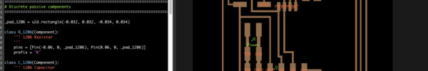
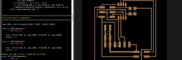
My idea was to completely design the electronics in Kokopelli. I have used Eagle CAD for the past electronic design and was in the mode to try something different. At first I was lost. I tried to use an example code from Neil to play around with. After many unsuccessful attempts and searches, I sent an email to Francisco. He replied "Kokopelli is not backward compatable." and then pointed me in the right direction to Juan Jo Fernandez's tutorial. Thanks! After this I had a framework to think on.
Next, I started on the kokopelli files. Athough this took a while at first there is a certain elangance to it. However, with little documentation makes it difficult. So I had more questions for the man Francisco. "How to I make the traces wider in Kokopelli?" which he replied.
pcb.connectH(IC1['PA4'], J1['SCK'],width=.04)
With this information I was able to complete the assignment.
Design it
I would like to design a network using serial and have two different types of motors for each node. One a DC motor and the other a servo motor. However, I got to the DC motor and LED nodes to work.
For the bridge and one of the nodes I transfered Neil's old kokopelli board into the new kokopelli. This gave me practice for designing my own board. I used the breakout board I designed last week and designed a node to go with the network and the breakout. Designing it was a lot of fun.
Make it
Alright, this has been the most frustating assignment so far. At first, I wanted to make a Neil's example network. Since this is the first time I used kokopelli for the electronics there was some issues.
First, kokopelli does not work with the Modela. The workflow was such: Kokopelli on Mac -> Export PNG file -> file share -> open Fab modules on Linux machine -> machine boards. The process is longer than necessary, need to get kokopelli working with Roland.
Second, Soldered all boards, smoothly. However, went to prorgam the boards, which gave me an error "Double check connections and try again, or use -F to override this check." Comes to find out the schematic in the kokopelli drawing (copy of Neil's) the LED was connected to the ground. So, I got out the exacto knive and started going to town.
After the event with the exacto knife I was ready to program again. I was set up to program one of the nodes and I smelt smoke. Ah Oh!!!!!!! I moved the device and saw the darnest thing. The ATtiny 45 come right off the board. Not COOL AT ALL!!
Ok, the next day I went back to the Fab lab with a rather large cup of coffee, actually a Iced Latte. Uhm! I made completely new batch of boards. Milling was the easy part. I went to solder the ATtiny 45 I pulled up a trace on the ground wire. DANG! The fix is shown in the picture below. taken with my phone and a magnifing glass.
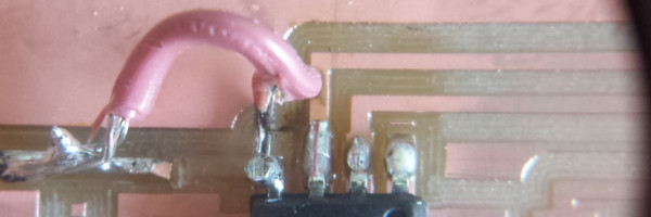
After the fix soldering went smoothly.
Program it
I liked this part two. It was not difficult to program the code. A slight modifications and combinations with the example codes. I also, modified the make file.
Below are the final codes:
Test it
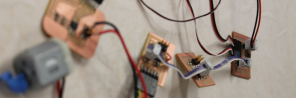
I followed the tutorial for networking at Fab Academy at AS220.[4]
I set the network up and it worked. I noticed when the node sent back a message it was not 'node = ' it was some garbage. However, it stopped working for some reason the second time I tried to type 2.
Troubleshooting
Flashed the node again and hooked it up to the network with no success.
Flashed Neils code on the node, no success.
Changed the nod_id to 3 flashed, no sucess.
Emailed the class and Neil said it maybe the bit clock time.
I modified the code line to read:
#define bit_delay_time 101
I tried the network again and was able to talk to the node. COOL!
Heck Ya! After many attempts. I have to say this was a rewarding victory .As usual, I learned more by failing then success. I know more about bit timers and reasons why things can go wrong. Furthermore, I know how to change th bit timing.
Since the video does not embed please see picture below. If you would like to see the video please do so.
Previous Successes
-
http://fab.cba.mit.edu/classes/863.13/people/charles/11/index.html
- http://fab.cba.mit.edu/classes/863.13/people/Hasier/Week12.html
- http://fabacademy.org/archives/2013/students/beaulisch.amy/weken/index_week14.html
- good example - http://fabacademy.org/archives/2013/students/sanchez.francisco/weekly-assignments/week-14/index.html
- http://academy.cba.mit.edu/2012/labs/providence/tutorials/15.html