Week Three: Computer-Controlled Machining
Goal
The third week goal was to design, make and document a press-fit construction kit using the laser cutter and cardboard.
Week Three Objectives
- Think of an idea for the construction kit
- Choose a software package that uses parametric design
- Create design in the software
- Laser cut the kit
- If necessary repeat steps
What I did?
The
idea for the construction kit was to design a opensource Hot Wheels
track that can be put together by kids. I wanted to have have
straight-a-ways, bends and rails for on each side of the track,
similar to a train track kit for kids, that I see in Barnes and
Noble. For the design and the software, I wanted to challenge
myself, I could use Solid Works but I know SW and it would not be
that difficult. Since, I liked kokopelli in the previous week I
chose kokopelli, although I know it would be more work. Plus, our
instructor said we use a lot of Python in the upcoming so I
wanted to par\y it forward and learn more on Python.
Kokopelli
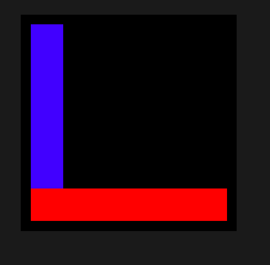
The first question I had was about the way the coordinate system is set up in kokopelli. What is the spatial framework for kokopelli? Is the working space in quad one or three. Some programs like Inkscape and Khan Academy work in quadrant four, and at first I did see the coordinate system switch. Therefore, I wrote and ran the small program below to find out. The red rectangle is long across the x axis starting from 0 to 6 units. The blue rectangle is long across the y axis starting at 0 and ending at 6. Each rectangle is 1 unit in the orthogonal direction.
kokopelli code
--------------------
from koko.lib.shapes import *
r1 = rectangle(0,6,0,1)
r1.color = 'red'
r2 = rectangle(0,1,0,6)
r2.color = 'blue'
cad.shapes = r1,r2;
--------------------
kokopelli image
--------------------
The positive coordinate system is in quadrant 1. Once I did this, I found out that you can turn on the axes with a click of a button under view -> Show axes.
Questions:
What units does kokopelli work in?
Kokopelli works in inches, I asked Francisco and verified this when I used the laser cutter.
How do I convert inches to mm?
I could write a function, however there is a command in kokopelli which is below.
|
cad.mm_per_unit=1 |
However, when I changed the units to mm, the screen did not refresh using the new units.
Why does this happen?
Next thought
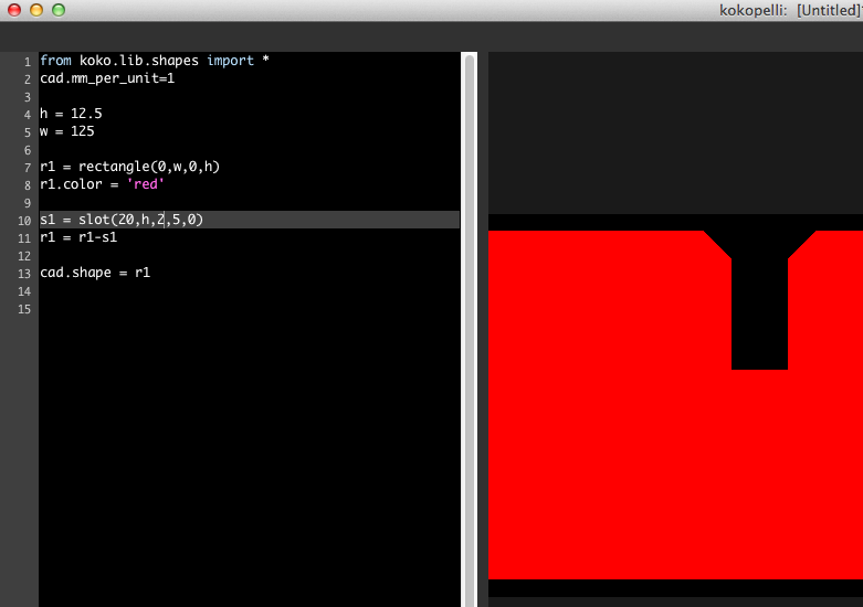
It is interesting to me when I started modeling a press fit gauge I found what i think is a bug in kokpelli. The height of the slot wa 3 mm. It does make a difference how you input the value in into kokpelli. If the height is (3.) you get a different outcome if the height is (3).
|
height = 3. |
height = 3 |
 |
 |
Pressfit Gauge:
A neat littke trick I learned is kokopelli can exepct a empty variable. "variablename = None"
The move command is based off the local coordinate system and the rotate command seems to be based on the global system. Further investigation required.
I
came up with a workflow strategy working in kokopelli which is
outlined below:
first create item on 0,0
rotate or reflect if necessary
then add or subtract while move command
loop and add move to make multiple parts.
This workflow is very convenient. It allows the program to reuse the item over and over again.
Program as of 2/14/14
Don’t know why the loop is ignoring the first item in the loop? the first number in the parentheses is bypassed by the program
Click HERE to download the program. This program identified a bug for the right_triangle command, which had no bounds for X and Y axis, therefore could not be exported. Matt Keeter was made aware of the problem and was quick to respond. The bug was ficed. Below is what the program output, it should be fine to print.

Finally installed fab modules on a Mac, followed instructions on the link below. First I did not download wxPython, so I went to wxPython page and downloaded wxPython3.0-osx-docs-demos-cocoa-py2.7, the cocoa version.
http://kokompe.cba.mit.edu/downloads.html
It
works. COOL!
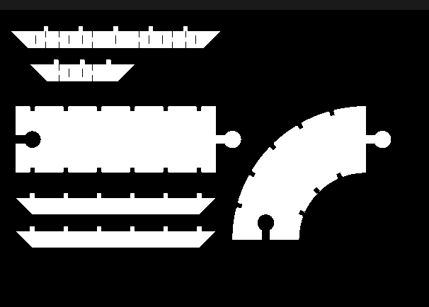
I started research flexure design for the side or the turn and found a lot of academic papers on flexure design, which is not what I was looking for. I found out the name is typically called a living hinge. I did not find much in the slot separation, so I took an educated guess. the below illustration is

Below is a kokopelli view of the final layout of the track.

Laser Cutter
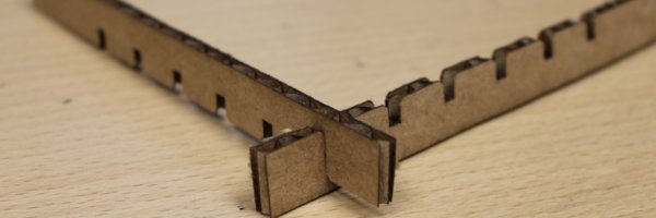

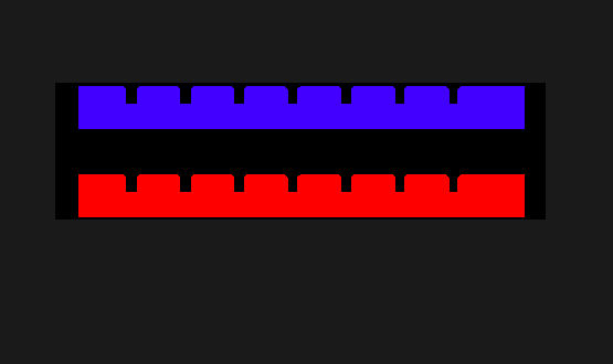
The above image shows the laser cutter in action cutting out the test pieces for the track. The circular tabs and circular slot fit together nicely, a tolerance of ten thousands of inch was parametrically built in, however the small tab and the slot did not fit. I needed to go into the code and change the fit. When I got to the code I noticed the tolerance variable was tied to both tabs. Therefore, if I modified the number I would modify both tabs, which is clearly not the intent. So, I changed to code to take to this into account. The tolerance I tried next was twenty thousands for the small tabs. After this, I cut out another test and the press fit worked, see below image.
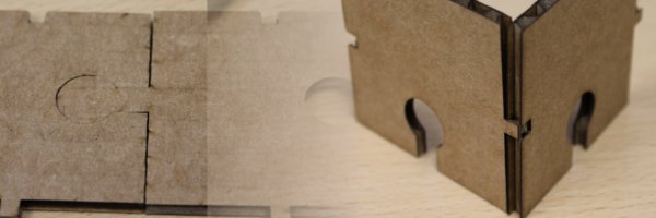
The final press fit construction kit is shown below. I tried to make a living hinge for borders, which did not turn out the way I liked. I was hoping for more bend-ability for the hinge. I believe I made the grooves to far apart. however, I also would like to try the hinge on wood to see how to behavior changes.

Inkscape?

Vinyl Cutter
For the vinyl cutter I chose to do three different stickers, one fairly large, one with thin features, and one that was multicolor. This was I could get a feel for many different types of stickers. The experience was eye-opening to say the least. Since, I never used the machine before, I am lucky to have my Lab Assistant Chris help me set the machine and walk me through some of the basics. For example, when using the machine how to set the origin and how to load the paper. Working through the Fab modules were fairly straight forward, since I worked on them for the laser cutter they were somewhat familiar to me.
A couple of things to note, the default force was 45 grams, however, the Lab Assistant said they have been cutting using 80 grams using the final and it has been working great. (So I changed the default setting) Another default setting was the speed was set to 5 (cm/2), which I believe the units are a misprint and should be 2 cm/s (minor, but noteworthy.) I modified the 5 to 20, due to the Lab Assistant's advice. Below are pictures of the process and my experiences with the vinyl cutter an the sticking process.
Black and White FabLab Sticker


YETI Robotics Sticker


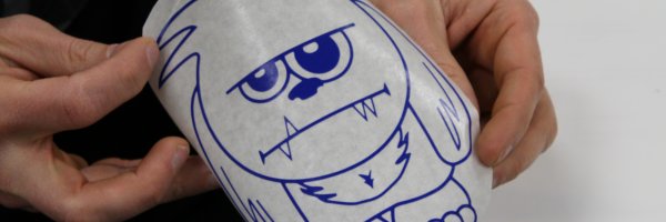


Final YETI turn out better than I thought, I recovered from the
mistake when I transferred the sticker onto the transfer paper I
flattened out the tooth beforehand.
Resources:
Found this, which you can learn a lot from this example. I was looking for for loops.
Found this for hinges using the
http://www.mit.edu/~calisch/linkage/3/3.html
Inspiration for the track.
http://fab.cba.mit.edu/classes/863.13/people/robert.hart/Week2/RobertHartWeek2.html#
Living hinge